This is an old revision of the document!
Table of Contents
1366 Series Screen Configuration Examples
The following examples show some of the available settings that were discussed in the MyCNC Screen Configuration manual. As an extremely large variety of possible settings and combinations are available, not every parameter discussed in the main manual is presented in the examples listed below. If any additional information is required, do not hesitate to reach out on the myCNC Forum.
Example 1: Add a button to display the Centring Widget (probe wizard)
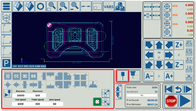
myCNC software has Centring widget to work with probing sensor and find internal and external centers, edges, corners on parts. In this example, we will be working with the 1366M4 profile to add a button which will open and close the centring widget when pressed.
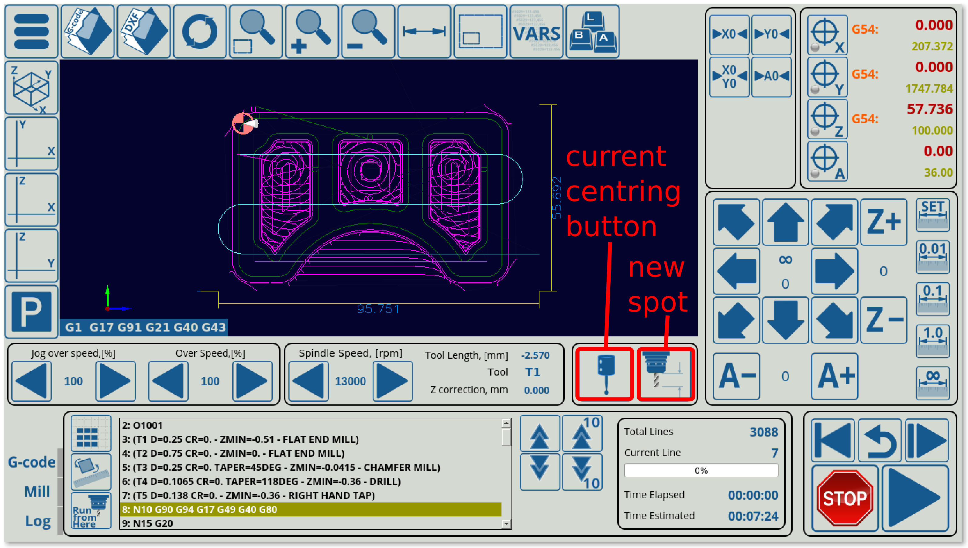
Note that the 1366M4 profile already has a centring widget with a dedicated button. For this example, the button next to the current probing wizard (centring widget) will be converted to also open up the centring window.
The following code describes the centring wizard button (this can be found in the x-speed-m.xml file, as this button is located in the x-speed-m section on the main software screen:
  <gitem where="x-reserv"
  position="8;5" width="80" height="80" image="probing/centring-unit"
  action="mywidget-toggle:x-centring" type="button"/>
The x-centring.xml file that can be found in the X1366M4 profile folder will describe everything that is inside the popup probing/centring window. However, to add a button that will bring up this popup, we simply have to add a button to another location and to assign to it the same action of toggling the x-centring window ON and OFF.
The easiest way to do this is to change another existing button (such as the Tool Measure button shown in the image above) as this will not require to shift any other buttons around to find some screen space into which the button will be inserted. The following code for the Tool Measure button is located in the same x-speed-m.xml file (as it is in the same section):
 <gitem where="x-reserv" position="92;5" width="80" height="80" image="button-tool-measure"
 action="mywidget-toggle:x-toolsview-main" type="button">
 </gitem>
Again, note how the where line is the same, as both the probe wizard and the tool measure buttons are in the same section.
In this code, we can switch the image line to read image=“probing/centring-unit”, and the action line to action=“mywidget-toggle:x-centring”, after which our code will look like this:
 <gitem where="x-reserv" position="92;5" width="80" height="80"
 image="probing/centring-unit"
 action="mywidget-toggle:x-centring" type="button">
 </gitem>
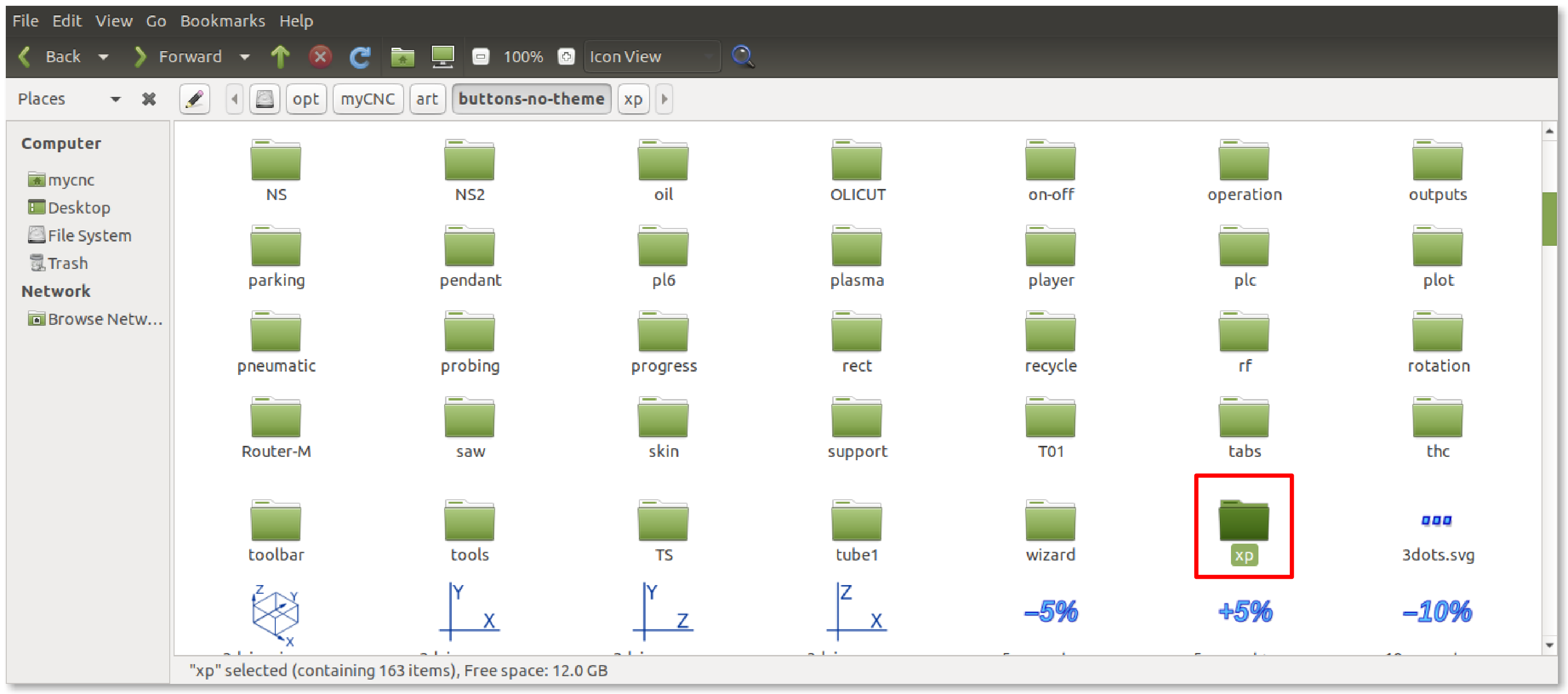
Note that the icons are located in your myCNC folder (typically opt/myCNC/art/buttons-no-theme/xp). If there is no xp folder (and the xp theme is specified), then the folder can be created. Read more about theme changes in the Theme and button skins manual.
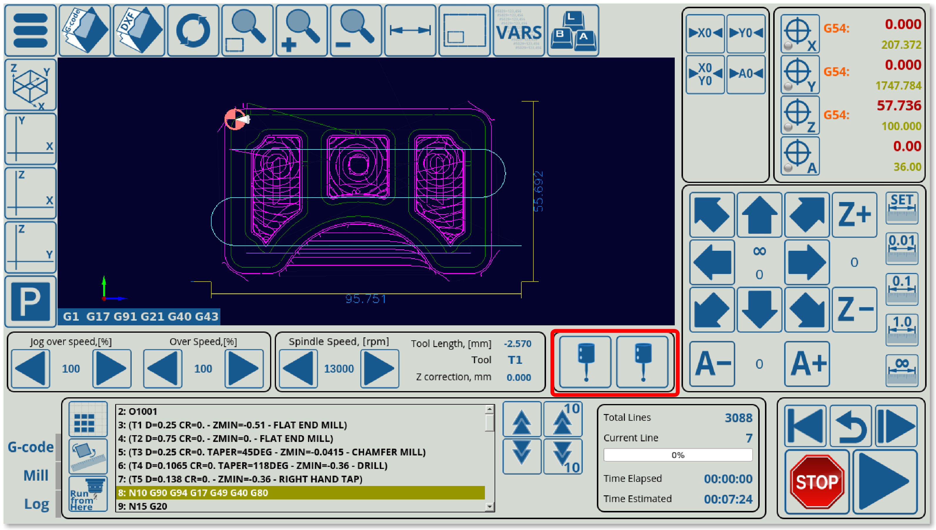
The resulting screen will now have two probe (centring widget) buttons which will both bring up the probe window:
It is also possible to delete the old centring button entirely, to edit it so as to use it as a tool measure button, or to assign a completely different display element in its place (as two probe buttons are unnecessary).
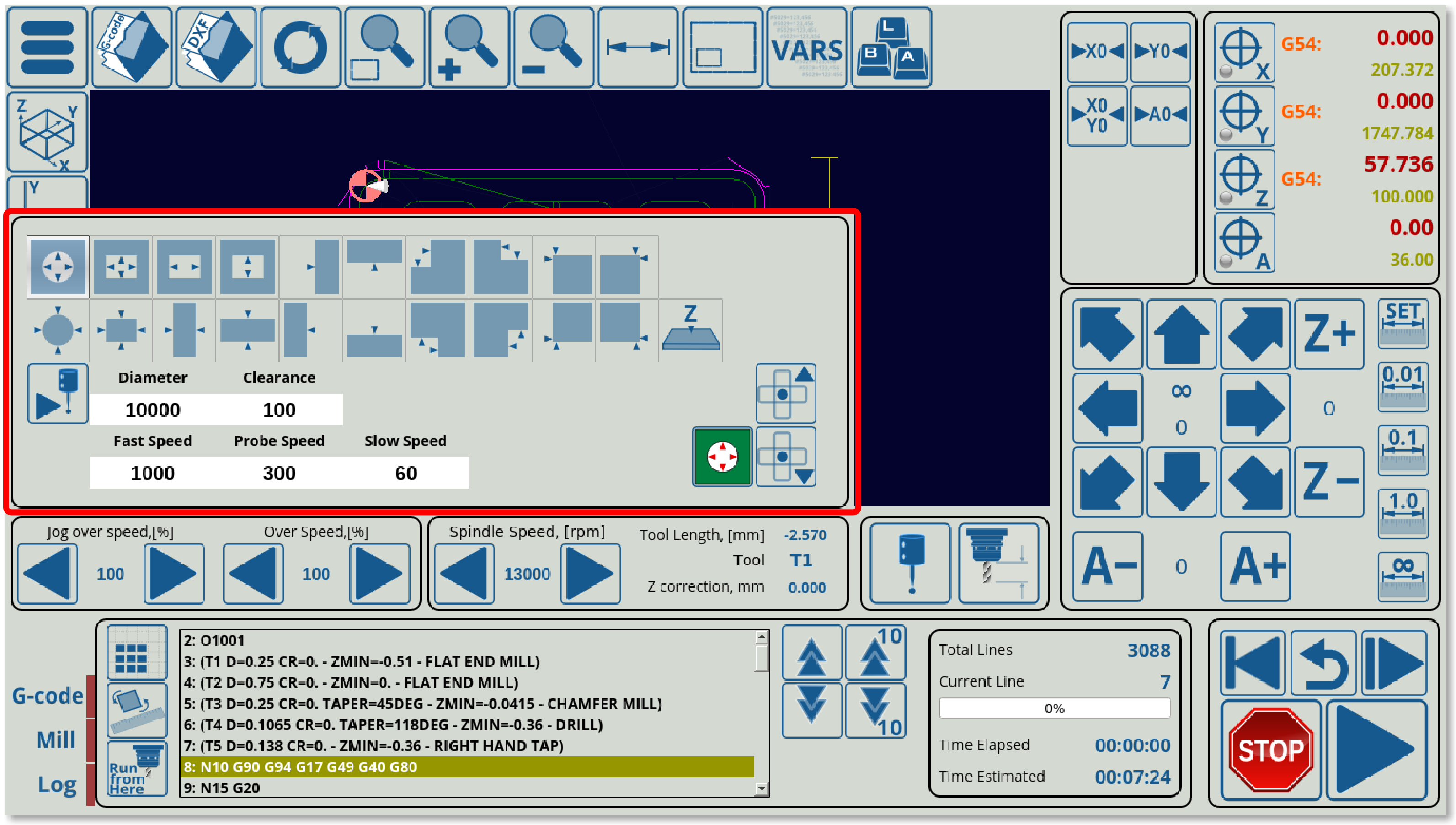
For any edits to the popup window itself, it is necessary to edit the full x-centring.xml file which is found in the X1366M4 profile folder. For example, in order to display the popup in a different location on the screen, it is possible to change the where=“xp” position=“0;490” hidden=“1” line.
For example, if the position value will be switched to 0;195 as compared to 0;479, the popup window will move up:
Note that in order to have this centring widget on the main software screen, one line of code is included in the main cnc-screen.xml file:
<include>x-centring.xml</include>
This will allow the main cnc-screen file to see that the x-centring MyItems widget is located in xp (main screen section). Without it, the centring widget (along with the tool measure widget, which is also defined in the same x-centring.xml file) will not work as the main screen file will not know to import the code from x-centring.xml.
Example 2: Adding new Gas ON/OFF buttons to 1366G profile
In this example, we will be taking the existing X1366G profile (the gas cutting profile) and adding two new buttons so that the operator is able to turn the gas ON and OFF manually. The images for these buttons are not bundled with the myCNC software at the time of writing this manual, so it serves as a good example on how to create a button (or a series of buttons) completely from scratch.
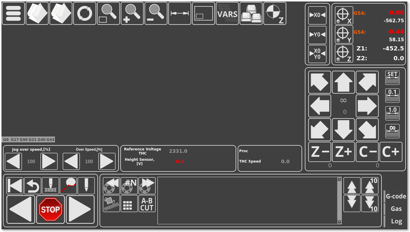
- The original screen of the 1366G profile looks like the screenshot below:
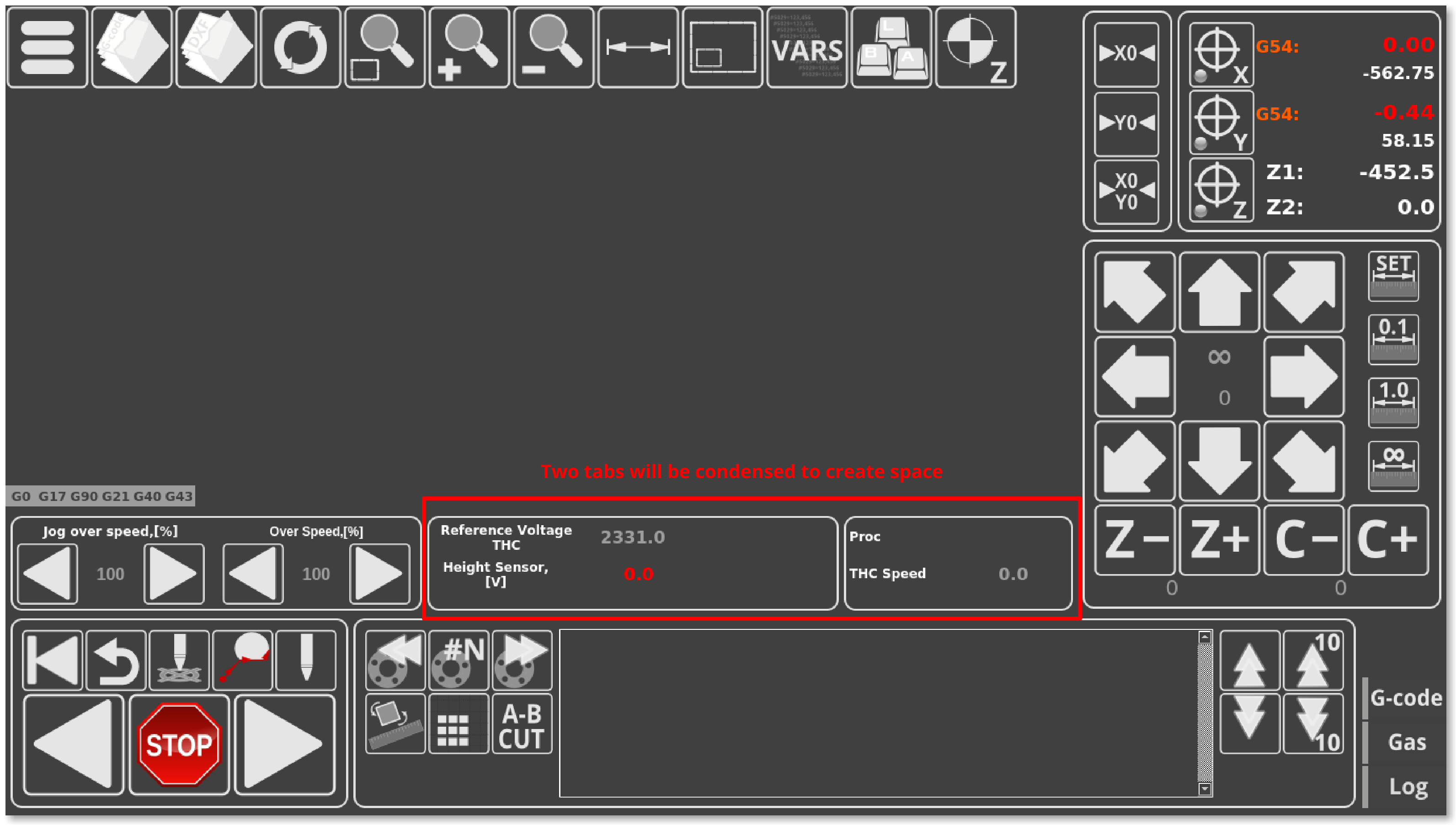
- The new buttons need to be inserted into some space on the main screen, so that they are easily accessible. No such readily available space exists on the screen at this point, so it has to be created. It has been noted that the functions in the two tabs next to the overspeed / jog overspeed buttons can be condensed into one tab.
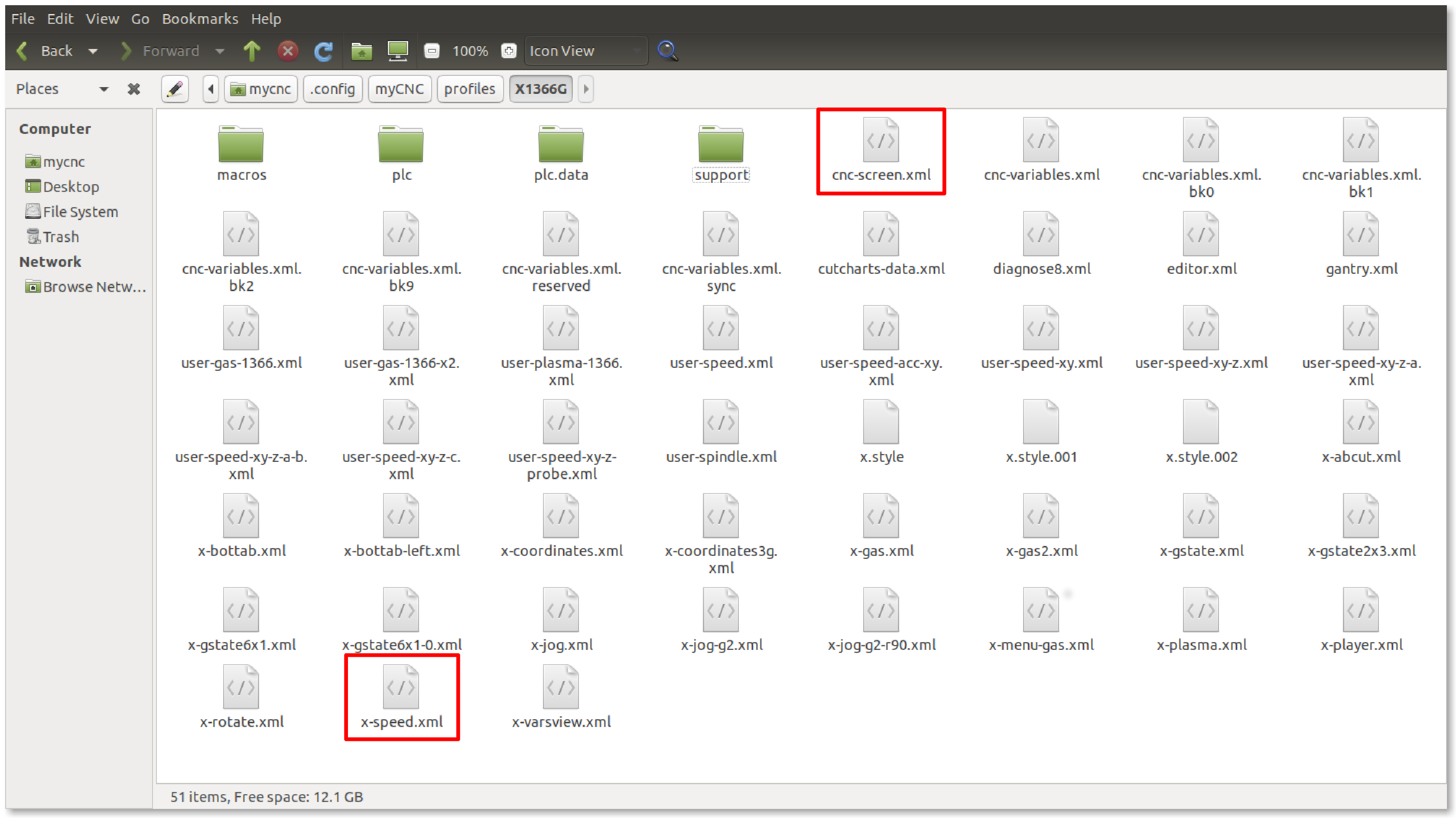
- In order to condense these tabs, we have to head into the config files for the myCNC application. Go to your Home folder, the navigate to
.config/myCNC/profiles/X1366G. In this folder, locate thex-speed.xmlfile and open it in the text editor of your choice (Pluma was used in this example). Note that different sections of the screen and different tabs can be described in different .xml files within the profile folder. What brings them all together is thecnc-screen.xmlfile which lists all the different files which are used when making the layout of the myCNC screen.
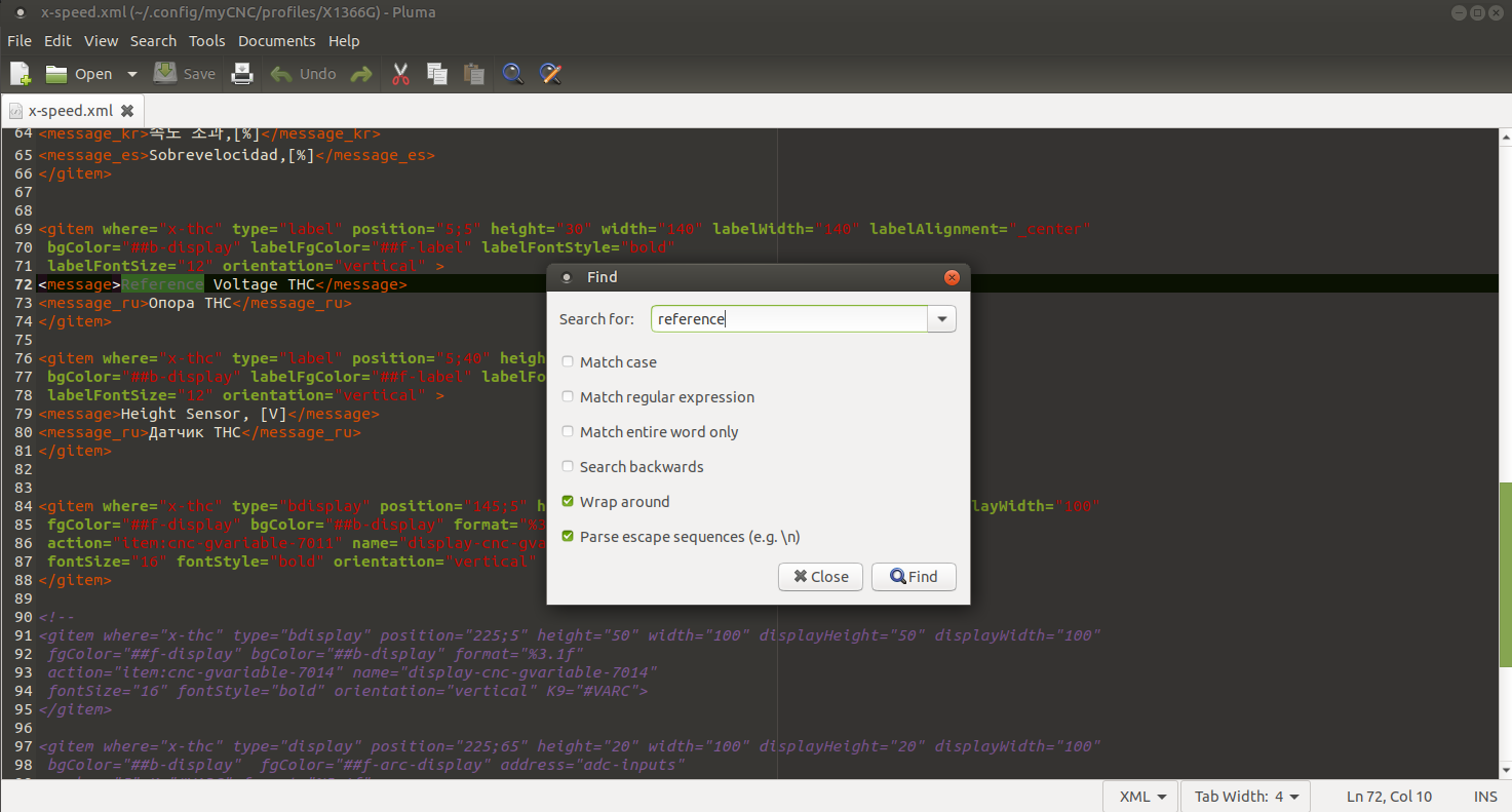
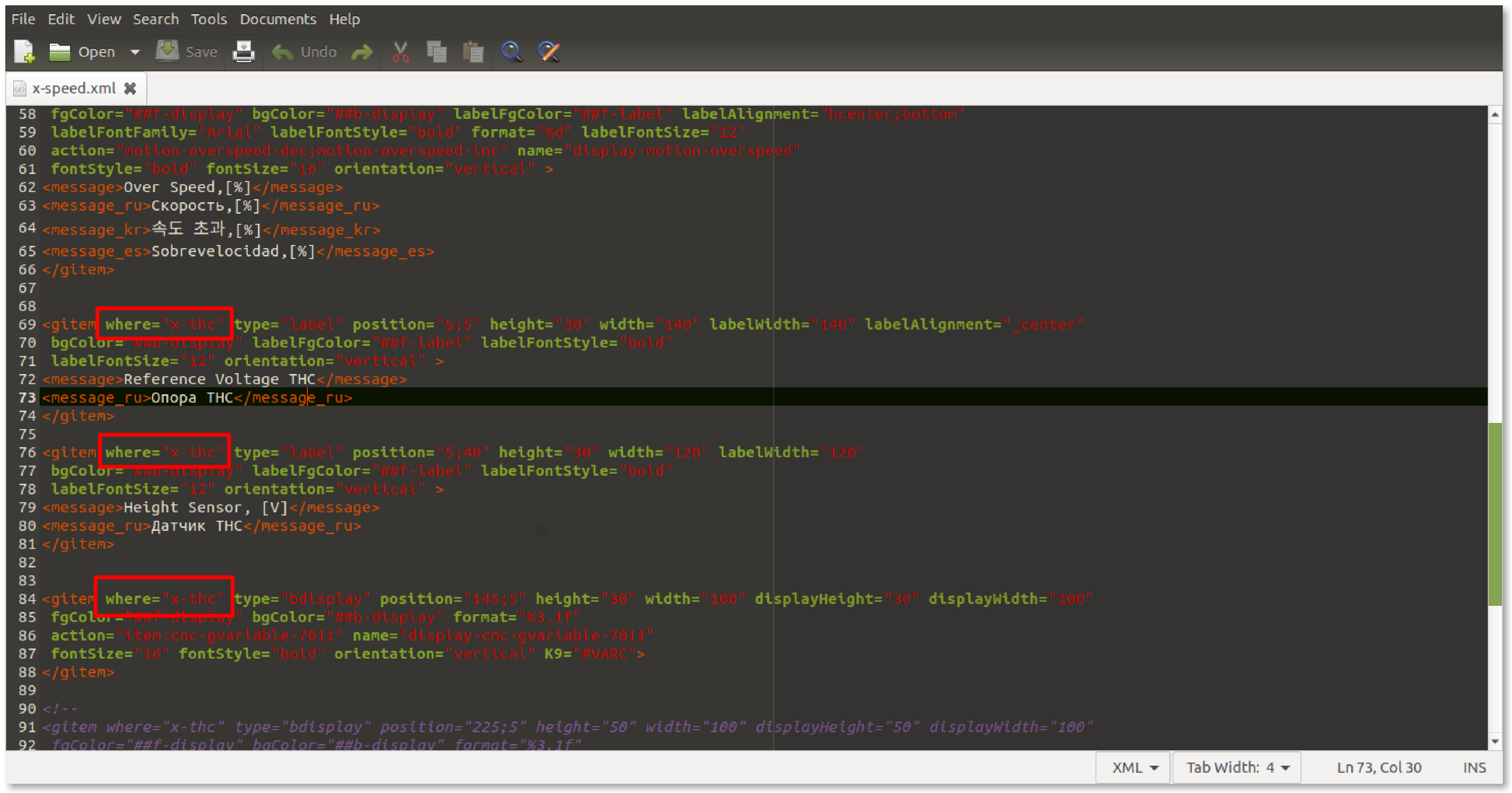
- In the x-speed.xml file, navigate to the section that describes the two tabs which will be condensed (the easiest way to do so would be to use the Ctrl+F function to search for the labels used within these tabs such as “Reference Voltage”)
- It can be seen that the
ProcandTHC Speedlabels are located in thex-reservsection, while theReference Voltage THCandHeight Sensorare situated in thex-thcsection (this can be seen in the“where=”field). We will condense the existing labels and display elements entirely into the x-thc, and the new buttons will be inserted into the now-vacant x-reserve tab.
- As a separate note, the Proc label will be removed during this example, as it is rarely used and will not be employed going forward on future myCNC builds.
- Alter the code to have the THC Speed label and its corresponding display element be in the
x-thctab instead of thex-reservetab, and remove the Proc label/display element entirely from the code. Note that the position of the THC Speed line is shifted downwards, as to not conflict with the screen elements already present withinx-thc.
<gitem where="x-thc" type="display" position="70;55" height="30" width="275"
 displayHeight="25" displayWidth="80" labelWidth="205"
 fgColor="##f-display" bgColor="##b-display"
 labelFontStyle="bold"  labelAlignment="_left" labelFgColor="##f-label"
 format="%5.1f" K="1."
 deviation="0.01" name="display-gvariable-5493"
 fontStyle="bold" fontSize="16" orientation="horizontal" >
<message>THC Speed</message>
<message_ru>Z Слежение</message_ru>
<message_es>THC velocidad</message_es>
</gitem>
- The x-reserve tab will be moved to the left, closer towards the overspeed buttons, while the x-thc tab will be moved to the right instead, as control buttons are typically positioned towards the left part of the screen in this profile. In order to do so, locate the code that defines x-thc and x-reserv elements within the text file (search for
name=“x-thc”andname=“x-reserve”). We will be changing their position values, as well as their width and basewidth values to accommodate for the buttons/labels within these tabs.
<gitem where="xp" position="563;484"
 width="450" height="90" basewidth="390" baseheight="90"
 type="frame" border-color="##b-border" border-width="2" border-radius="10"
 name="x-thc" bgColor="##b-main" />
<gitem where="xp" position="401;484"
 width="155" height="90"
 basewidth="155" baseheight="90"
 type="frame" border-color="##b-border" border-width="2" border-radius="10"
 name="x-reserv" bgColor="##b-main" />
- Next, the images for the new Gas ON/OFF buttons need to be added to the myCNC image folder. Note that this is NOT the same folder/path as the profile folder described earlier. The images will need to be added to the theme folder (currently “xp”, as described in the Settings > Config > Screen > Theme field), which will be located (on Ubuntu machines) in
opt/myCNC/art/buttons-no-theme/xp. Note that the last bit of this folder path changes depending on the theme specified in myCNC settings, however the xp theme is used as it is the default on 1366 series profiles.
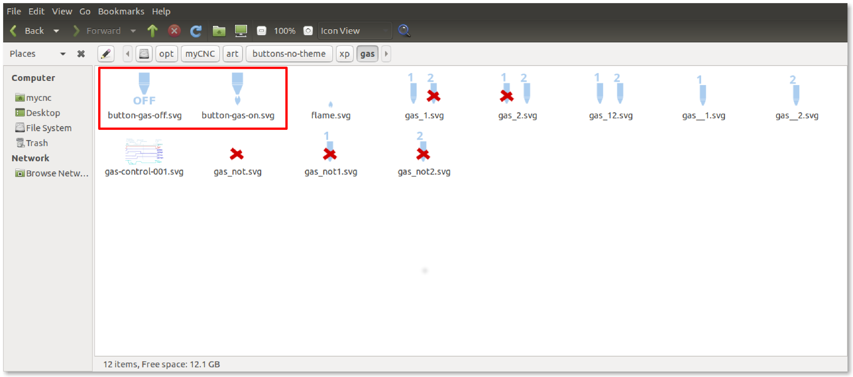
- The two buttons that will be used to turn the gas on and off currently do not have their respective images. These will be added to the
gasfolder within thexptheme folder described above. They will be calledbutton-gas-on.svgandbutton-gas-off.svgrespectively. The images are created using a program capable of making an .svg file, like Inkscape (free, open-source vector graphics application).
- Within the currently existing x-reserv tab, we will now add an
x-reserv-viewMyItems element, as to allow to show buttons and images within the frame. From here on, the buttons will be inserted intox-reserv-viewrather than directly intox-reserv.
<gitem where="x-reserv" name="x-reserv-view" position="2;2"
 width="155" basewidth="90"
 height="155" baseheight="90"
 type="myitems" />
- Above the images that we will be inserting, it is often advisable to create a label in order to denote what the buttons are meant to do. In our example, the button will simply say “Gas”:
<gitem where="x-reserv-view" type="label" position="44;0" height="20" width="70" labelWidth="70"
 bgColor="##b-display" labelFgColor="##f-label" labelAlignment="_center" labelFontStyle="bold"
 labelFontSize="12" orientation="vertical" >
<message>Gas</message>
</gitem>
- At this point, the code for the gas buttons can be inserted. Note how the folder path is written out for the images that we have created and saved in the
gasfolder within thexptheme folder:
<gitem where="x-reserv-view" position="11;23"
 width="60" height="60"
 image="gas/button-gas-on"
 action="TURN-GAS-ON"
 type="button" />
<gitem where="x-reserv-view" position="81;23"
 width="60" height="60"
 image="gas/button-gas-off"
 action="TURN-GAS-OFF"
 type="button" />
NOTE: THE ACTIONS CURRENTLY USED IN THIS CODE ARE PLACEHOLDERS.
CORRECT ACTIONS WILL BE ADDED LATER
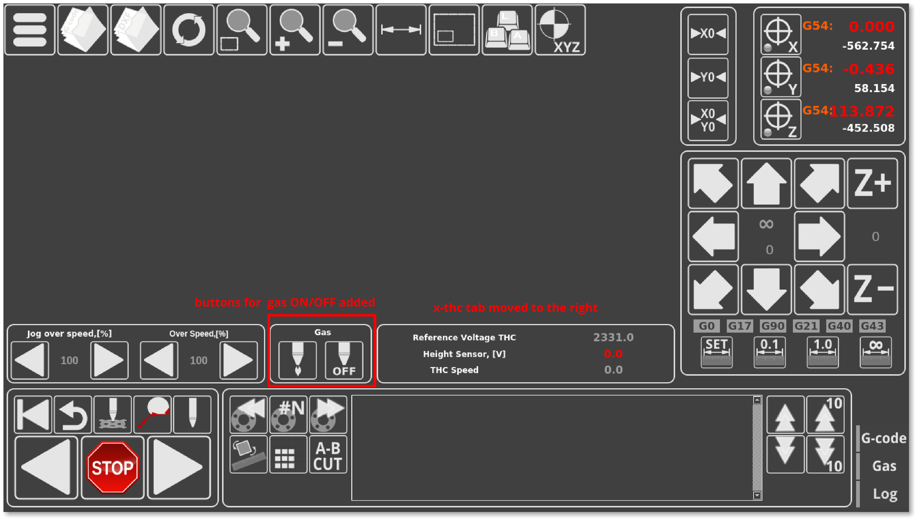
- At this point, after saving the
x-speed.xmlfile and reloading the myCNC application, your screen should look like this:
As can be seen in the screenshot above, the program now has two new on-screen buttons for gas on/gas off, as well as having the previously available information condensed into relocated x-thc tab.
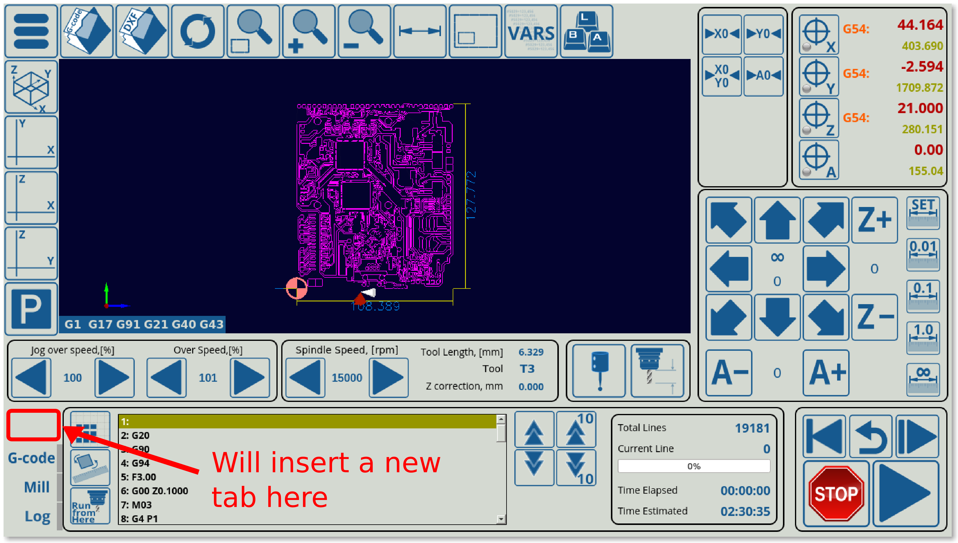
Example 3: Adding a tab next to the Mill, Log and G-code tabs
In this example, we will be editing the existing 1366M4 profile by adding a new tab to the already existing Mill, Log and G-code tabs which can be found on the bottom of the main profile screen. This tab will contain some buttons to adjust the current G-code program file with regards to a z-height map of the working material that will be created using a probe (a similar feature already exists on the X1366V profile at the time of writing this manual).
- The code for the bottom tab can be found in the
x-bottab-left-mill.xmlfile in the main profile folder (X1366M4). This file should be specified in thecnc-screen.xmlfile, to indicate to the program that this code will be included on the main screen. The line in thecnc-screen.xmlfile should look the following:
<include>x-bottab-left-mill.xml</include>
Note that this file (the file containing the bottom tab code) is different for different profiles - for example, the 1366V profile uses the x-bottab-camera.xml file instead.
- Upon opening the
x-bottab-left-mill.xmlfile, find the following chunk of code:
<gitem where="x-bottab" name="x-mill" position="85;0"
 width="1040" basewidth="1040" height="180" baseheight="180"
 type="frame" border-color="##b-border" border-width="2" border-radius="10"
 bgColor="##b-main"  hide-list="x-nclist;x-log" exclusive="yes"  />
- This is followed by similar code for x-log and x-nclist, and outlines the basics of each of the three already existing tabs. First of all, it is necessary to add a fourth chunk of code, which we will call
x-mapping.
<gitem where="x-bottab" //x-mapping is within the x-bottab screen
 name="x-mapping" position="85;0" //position within the x-bottab screen
 width="1040" height="180" basewidth="1040" baseheight="180" //element parameters
 type="frame" border-color="##b-border" border-width="2" border-radius="10"
 bgColor="##b-main" hide-list="x-log;x-mill;x-nclist" exclusive="yes" />
Note that the hide-list for this code specifies all the other tabs that will be hidden when the x-mapping tab is open. Note that the exclusive flag is set to “yes”, indicating that only one such tab/window will be open at one time. In a similar fashion, it is necessary to add that x-mapping will be hidden when the other tabs are open in their respective code. For example, the Mill tab will have its code altered like so (each of the other tabs will have to have x-mapping added to the hide-list):
<gitem where="x-bottab" name="x-mill" position="85;0"
 width="1040" basewidth="1040" height="180" baseheight="180"
 type="frame" border-color="##b-border" border-width="2" border-radius="10"
 bgColor="##b-main"  hide-list="x-nclist;x-log;x-mapping" exclusive="yes"  />
- Next, the button to switch to the Map tab will be added. It is done through the following code:
<gitem where="x-bottab" position="5;12" //button also added to x-bottab
 width="80" height="40" skinbase="flat" //skinbase is located in the theme (xp) folder
 xattr="0;0;80;40;led;red;round" //creates an LED
 images="vbutton-right-led-off;vbutton-right-led-on" address="widget" //assigns LED images
 image="mapping-left" //assigns the image for the button
 action="mywidget-show:x-mapping" type="xbutton"/> //specifies the result of pressing the button
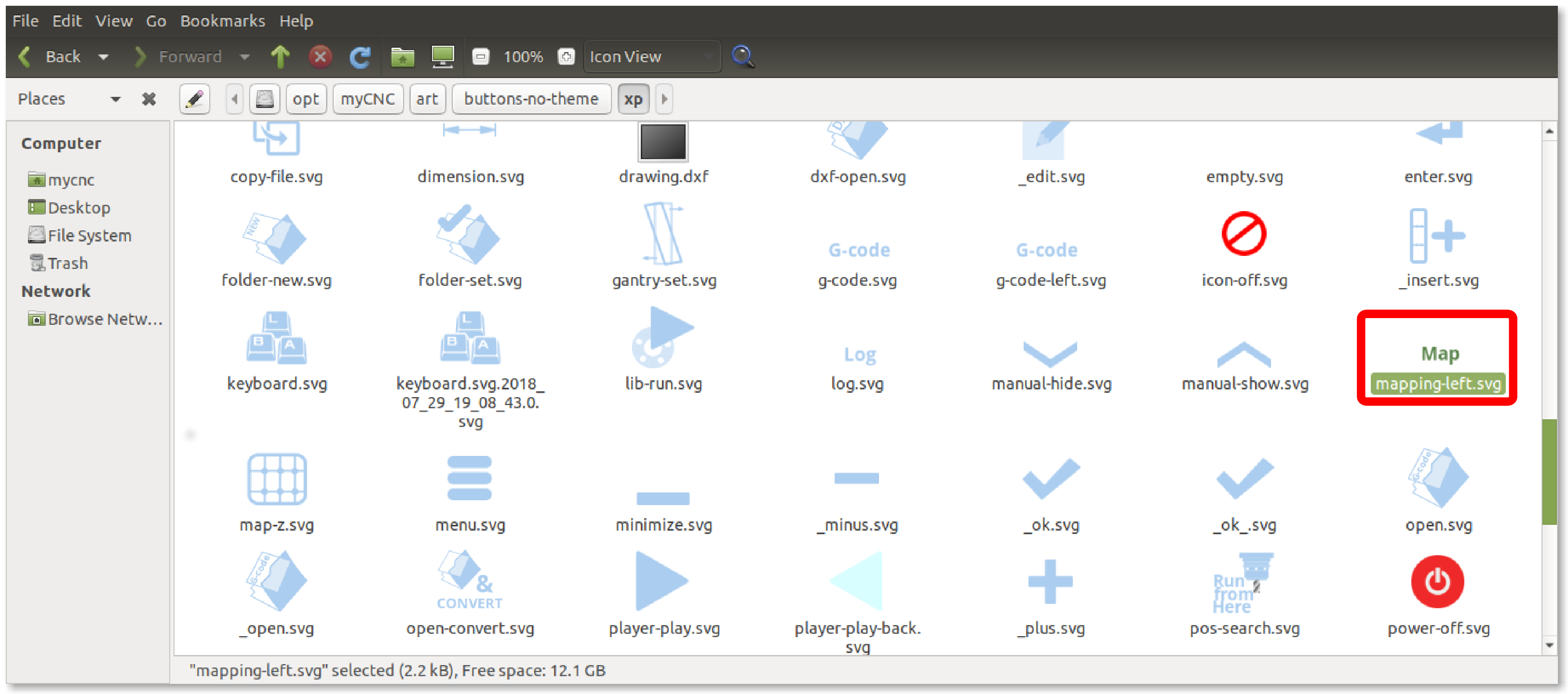
- Note that this refers to an image that is not used anywhere else in the application, so it is necessary to create it. We can do so by adding a new image with the name
mapping-left.svgto themyCNC/art/buttons-no-theme/xpfolder (if the default xp theme is used). An image with the word “Map” was created and added to that folder in this step using the Inkspace application (any application which can edit and export .svg files will work):
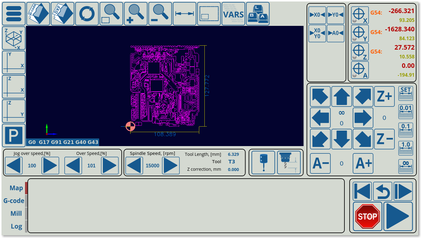
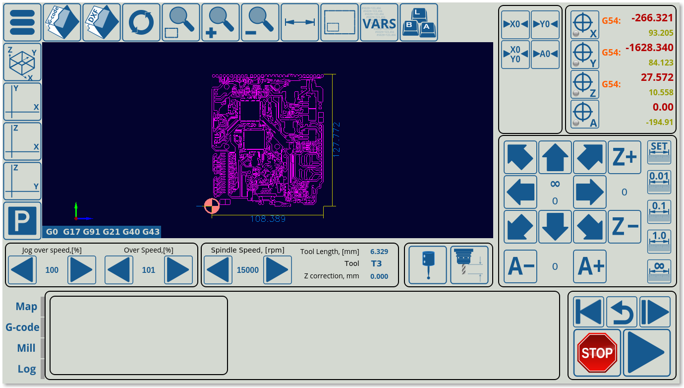
The screen should look like this at this point (note the newly added blank tab in the bottom section of the program):
- Next, the frame around the buttons inside the x-mapping tab will be inserted using the following code:
<gitem where="x-mapping" //will insert this element inside x-mapping
 name="map-z-frame" position="10;10" //creates a visual border element
 width="360" basewidth="360" height="160" baseheight="160"
 type="frame" border-color="##b-border" border-width="2" border-radius="10"
 bgColor="##b-main"  hidden="no" /> //note that hidden can be expressed both with "no" and "0"
The frame will appear in the previously blank Map tab (not filling in the entire tab, as its width and height have only been specified to be 360,160)
- Inside this frame, the map-z-view element will be inserted. Note that this code does not change anything visually, as it simply creates a new section within the existing frame into which other visual elements will be inserted in the next steps:
<gitem where="map-z-frame" name="map-z-view" position="5;5"
 width="350" basewidth="350"
 height="150" baseheight="150" //basewidth/height serve as reference values for resizing
 type="myitems" />
- Inside the map-z-view, which is our actual window of the tab, the two buttons and the RadioDisplay element will be inserted:
<!--BUTTON FOR MAP GENERATION-->
<gitem where="map-z-view" position="5;5"
 width="70" height="70"
 image="probing/map-z-probe"
 action="zmap-generate"
 type="button" />

<!--BUTTON FOR APPLYING THE GENERATED MAP TO THE ORIGINAL FILE-->
<gitem where="map-z-view" position="75;5"
 width="70" height="70"
 image="probing/map-z-convert" //the probing folder will be taken from the theme folder (ex: xp)
 action="zmap-apply"
 type="button" />

<!--SELECTION OF AREA/RECTANGLE FOR PROBING-->
<gitem where="map-z-view" position="150;5"
 displayWidth="110" width="110" height="70"  displayAlignment="_center"
 fgColor="##f-display"
 format="Rectangle;Area" fontFamily="Open Sans" fontSize="20"
 type="radio-display" deviation="0.5"
 action="cnc-gvariable-toggle-8255"
 name="display-cnc-gvariable-8255" //both the action and the display show the 8255 gvariable
 bgColor="##b-display" fontStyle="bold">
</gitem>
- Near these buttons, the other necessary elements of the window will be added. In this example, these are used to show that we can now keep adding buttons, frames and other display elements into the already existing
x-mappingtab (and specifically, into themap-z-viewwithin themap-z-frame) that we have created.
<gitem where="map-z-view" position="5;80"
 displayWidth="60" width="200" height="30"  displayAlignment="_center"
 labelWidth="140"
 fgColor="##f-display"
 format="%1.1f" fontFamily="Open Sans" fontSize="20"
 type="bdisplay" deviation="0.05"
 action="item:cnc-gvariable-8250"
 name="display-cnc-gvariable-8250"
 bgColor="##b-display" fontStyle="bold">
<message>Segment Length,[mm]</message> //BDisplay shows both a global variable and a label
</gitem>

<gitem where="map-z-view" position="5;110"
 displayWidth="60" width="200" height="40"  displayAlignment="_center"
 labelWidth="140"
 fgColor="##f-display"
 format="%1.1f" fontFamily="Open Sans" fontSize="20"
 type="bdisplay" deviation="0.05"
 action="item:cnc-gvariable-8251"
 name="display-cnc-gvariable-8251"
 bgColor="##b-display" fontStyle="bold">
<message>Measure Grid X*Y,[mm]</message>
</gitem>

<gitem where="map-z-view" position="205;110"
 displayWidth="60" width="80" height="40"  displayAlignment="_center"
 labelWidth="10"
 fgColor="##f-display"
 format="%1.1f" fontFamily="Open Sans" fontSize="20"
 type="bdisplay" deviation="0.05"
 action="item:cnc-gvariable-8252"
 name="display-cnc-gvariable-8252"
 bgColor="##b-display" fontStyle="bold">
<message>*</message>
</gitem>
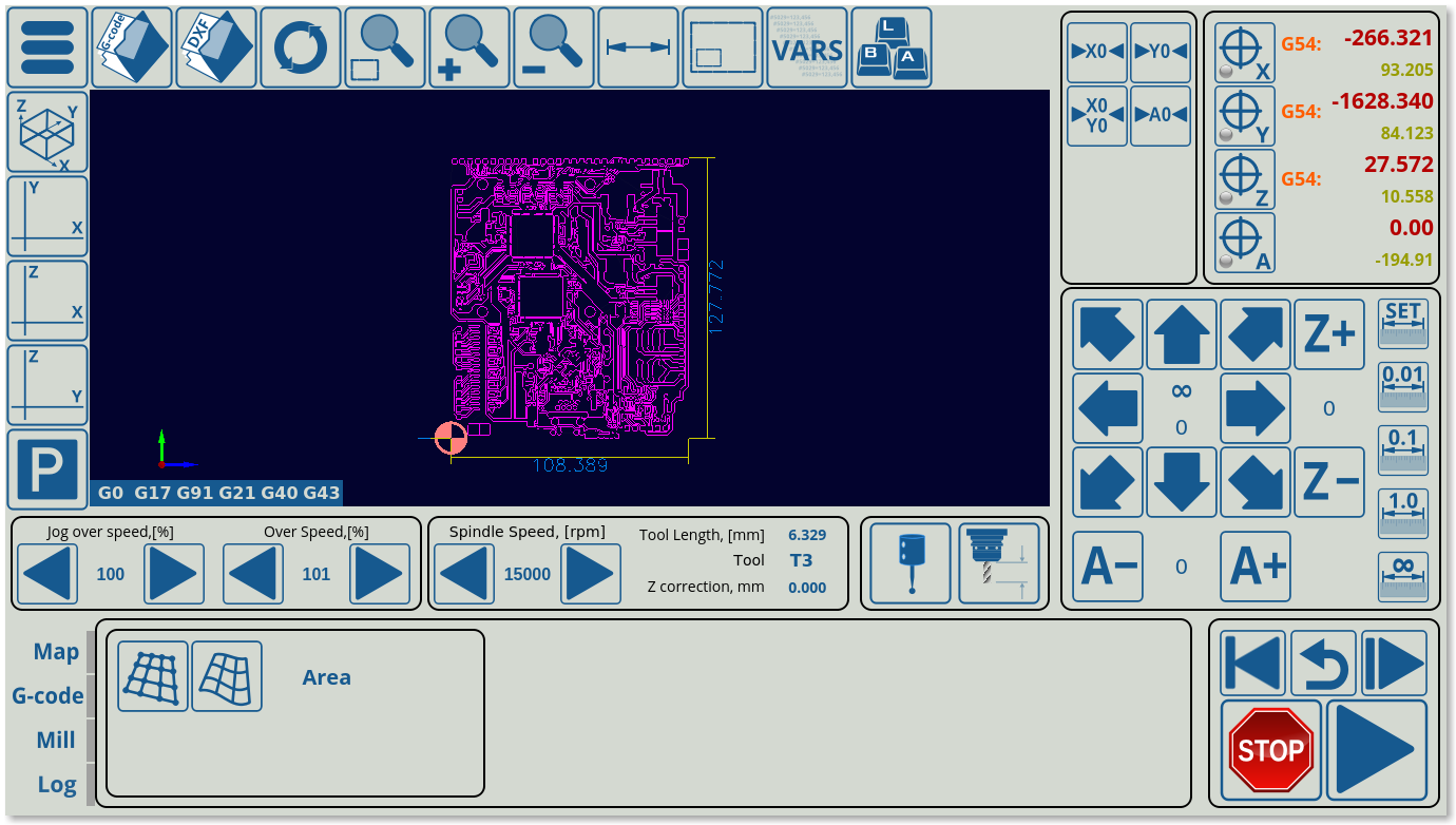
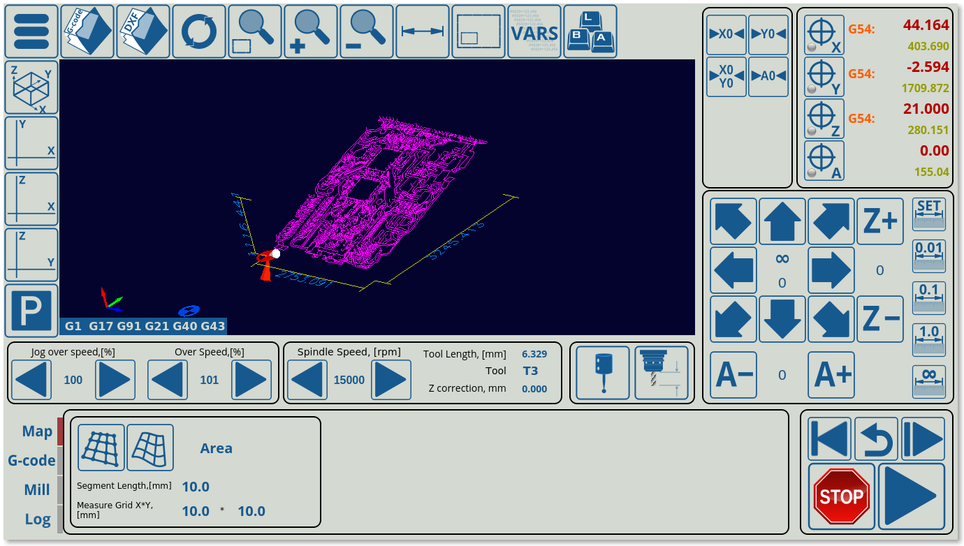
The final result will look like this, with the frame containing the buttons and other on-screen elements within the x-mapping tab visible when clicking the newly created Map button:
From here on, it is possible to continue adding display elements to this tab in the remaining space, by creating subsections similar to the map-z-frame section created earlier. See more information on the possible screen elements in the MyCNC Screen Configuration manual.
====Example 3:

