mycnc:jog_through_adc_inputs
This is an old revision of the document!
Table of Contents
Jog through ADC inputs
Main window: Basic functions:
- ADC-а device that converts the input analog signal into a discrete code (digital signal). In this case, the incoming analog signal is proportionally converted into a control signal of displacements along the selected coordinate.
- To activate the Jog through ADC inputs, it is necessary to check the box next to number of channel:
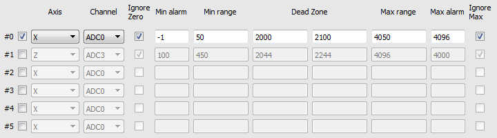
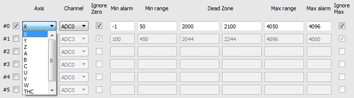
- Next you need to select the axis by which the control will be carried out using an analog signal. It is also possible to select a vertical support control system during tracking (TNC).
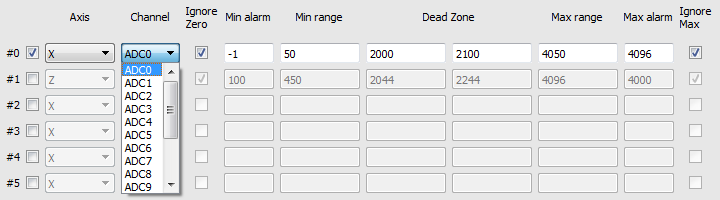
- It is also necessary to choose the number of the ADC input channel on the controller, where the analog signal from the analog control (analog-joystick) will go directly.
- The processor input is usually designed to measure an analog signal in the range of 0 to 5V. Correspondingly inside the processor, this analog signal will be converted to a digital value from 0 to 4096. Where 0 is 0V, and 4096 is 5V.


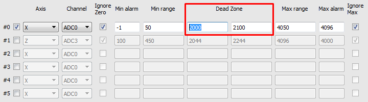
- In CNC machines, as a rule, the source of the analog signal and the main control is the joystick. The most convenient and most common are joysticks based on Hall sensors with power supply + 5V and output signals 0-2.5V-5V. Where the level 2.5B corresponds to the position of the joystick at rest, i.e. the controlled axis is not subject to control. .After converting the analog signal to 2.5V, the digital value of 2048 corresponds to the digital value of 2048. Typically, joysticks and similar control devices at the output, even at rest, have small distortions and noises in the output signal. To prevent false positives and unauthorized movements, a “dead zone” is entered in the settings.
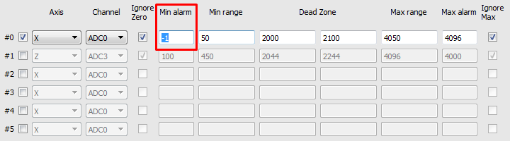
- “Dead zone” - is set by two values of the lower and upper limit of the values of the input signal, in the range of which the system will not respond to the input signal and system movements and other reactions to the joystick will be absent. For example, the system will not perform any reactions or actions in the range of values from 2000 to 2100, which in turn corresponds to the input signal levels in the range from 2.44V to 2.56V.
- Accordingly, 0V is a movement to the left or counterclockwise, at the maximum speed and 5V is movement to the right or clockwise at the maximum speed.The value of the signal in the range from 0 to 2.5V - allows a smooth, adjustable movement to the left or counterclockwise, and accordingly the signal value from 2.5V to 5V allows a smooth, controlled movement to the right or clockwise.

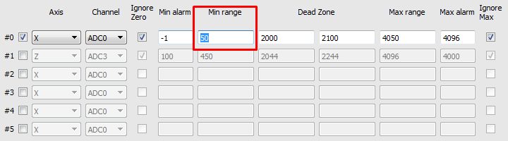
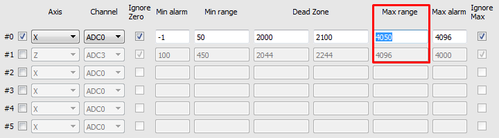
- Also in the program is designed to protect against breakage of the joystick itself or broken wires. Because when the cable is cut from the joystick to the controller input, the level of the input signal will be equal to or close to 0V (0). Also, for certain errors in the wiring, it is possible for a false alarm to occur at 5V level (4096) at the controller input. To prevent movement with such errors in the program, you can set the minimum and maximum level of the signal at the input to the controller. For example, the minimum signal level is set to 50, which corresponds to 0.06V, and the maximum level is set to 4050, which corresponds to 4.94V.


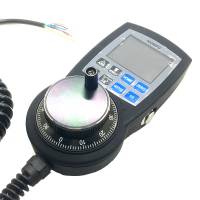
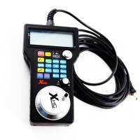
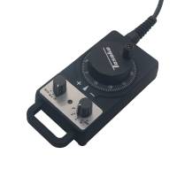
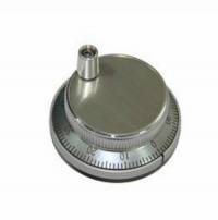
- MPG - designed for manual control of the CNC without resorting to control from the operator panel. With the help of the control panel, the operator of the CNC machine can change the position of the axes, change the feedrate, adjust the spindle operation, set “0” and perform other operations while in close proximity to the workpiece.
- examples of MPG are presented below:
 |  |  |  |
- After activation, you can select the operating input numbers for the MPG on the controller - input1 and input2
input1:
 input2:

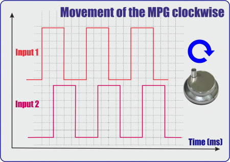
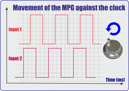
- Timing diagram of signals of MPG:
 |  } } |
- It is also necessary to select the MPG function:
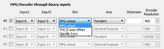
| Functions | Discriptions |
|---|---|
| MPG wheel | Direct control of MPG |
| THC/Z axis offset | Controlling the tracking on cutting with the help of MPG |
| Spindle Sync | Spindle control, via the analog output to control the spindle speed. |
- If necessary, select the coordinate axis, which will be controlled by MPG
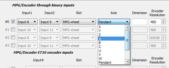
- Next we select the length of displacements with the help of MPG. Number of movements in mm per pulse MPG:
- We set the resolving power of the PGM - the number of pulses per one revolution of PGM
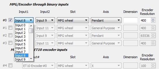
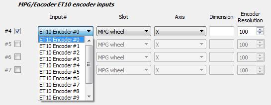
Mpg/Encoder ET10 throught binary inputs
If you use the ET10 controller https://shop.pv-automation.com/et10/9-mycnc-et10.html, you can used not only MPG function, but also the encoders, to monitor the position of any of the axes.
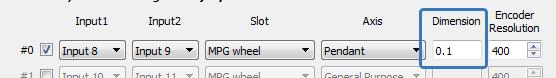
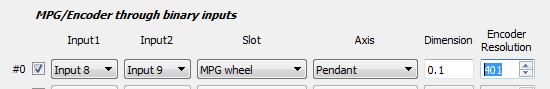
- To activate the MPG or Encoder, it is necessary to check the box next to needed number:
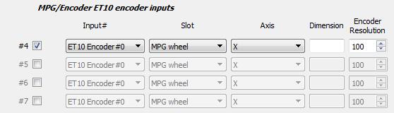
- After activation, you can select the encoder number on the controller for operating
- It is also necessary to select the MPG function:
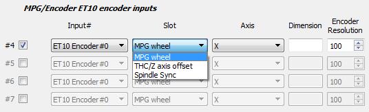
| Functions | Discriptions |
|---|---|
| MPG wheel | Direct control of MPG |
| THC/Z axis offset | Controlling the tracking on cutting with the help of MPG |
| Spindle Sync | Spindle control, via the analog output to control the spindle speed. |
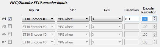
- If necessary, select the coordinate axis, which will be controlled by MPG

- Next we select the length of displacements with the help of MPG. Number of movements in mm per pulse MPG:
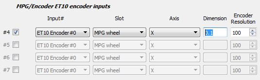
- We set the resolving power of the PGM - the number of pulses per one revolution of PGM
mycnc/jog_through_adc_inputs.1536178765.txt.gz · Last modified: 2018/09/05 16:19 by pupalaiser