This is an old revision of the document!
Table of Contents
MyCNC Configuration Dialogs
Axes/Motors
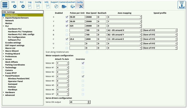
The main axes-motors parameters can be configured in the settings by going to CNC Settings > Axes/Motors
- Enabled. Each of the motors for axes X,Y,Z,A,B,C,U,W,V can be enabled or disabled. If any axis is disabled the software ignores All coordinates for this axis and does not send any motion to this axis. It is convenient to disable the axes you don't use on your particular machine.
- Pulses per unit. This parameter sets the number of pulses which the controller sends to the motor drivers to move by 1 unit distance (the unit depends on CNC configuration and can be either “mm” or “inch”). The full instructions on pulses per unit setup can be found on the QuickStart page here.
- Max Speed - CNC control will limit machine speed for each axis by this value. Note that the Max Speed does not count the override % value. Be careful if you use override values more than 100%
- Backlash - Backlash value in units (mm/inch) for each axis (different for each machine depending on the hardware specifications)
- Axes Mapping - Toolpath planner uses this setting for tool motion speed calculation. Possible settings are-
- “X”, “Y”, “Z”, “U”, “V”, “W” - linear axes X, Y, Z, U, V, W
- “A1”, “B1”, “C1” - rotation around axes X, Y, Z. Tooltip makes a circle-like motion on a material surface while the A/B/C axis is turning (a rotary table, 4th rotary axis, etc).
- “A2”, “B2”, “C2” - tilt around axes X,Y,Z. Tooltip position is not changed while the A/B/C axis is turning. Only the tool orientation is changed (a rotating tangential knife, a 3D plasma bevel head, etc).
- “Linear axis” - additional linear axis (any linear axis the behaviour of which cannot be described as an X/Y/Z/U/V/W axis)
- “Rotary axis” - additional rotary axis (any rotary axis the behaviour of which cannot be described as an A/B/C axis)
- Speed profile - additional settings to optimize Speed profile for rotary axes
- “Constant surface speed” - Tooltip is moving on the surface of turning material. Turning speed is calculated depending on the given F-feedrate and the tooltip cutting speed on the surface (It's supposed that a tooltip is moving in an arc motion with radius depending on current XYZ position).
- “Slave Of XYZ” - Current speed calculated for X,Y,Z axes depending on a given F-feed rate. Turning speeds for rotary axes are adjusted to get synchronous motion.
- “Spherical correction” - Settings for 3D bevel cutting head and RTCP kinematic correction.
- Attach to axis. Any of 6/8 motor output can be attached to any axis. Here you can select what axis is used for every motor output.
- Inversion - Mark the checkbox if you need to change the rotation direction for any axis.
For Dual axis configuration just attach one axis simultaneously
to two (or more) motor outputs. For example, in the picture above,
Motor outputs #0 and #1 are used for X-axis. Inversion is selected
for Output #1, so both motors connected to Output#0 and Output#1
will be rotated simultaneously, but in the opposite direction
Inputs/Outputs/Sensors
Alarms
myCNC software supports a number of Alarm input.
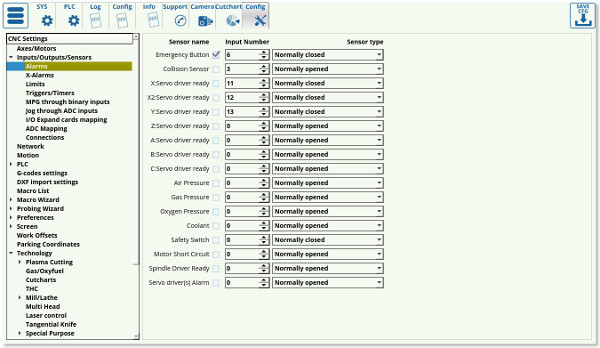
Any of myCNC controller binary input can be programmed as Alarm input. Alarm inputs setup is available in Alarms configuration dialog. In the dialog -
- Each Alarm can be enabled or disabled
- Any binary input can be assigned as selected Alarm
- Input type Normally opened or Normally closed can be selected to the alarm.
MyCNC software has different Handlers for Alarm.
Emergency Button
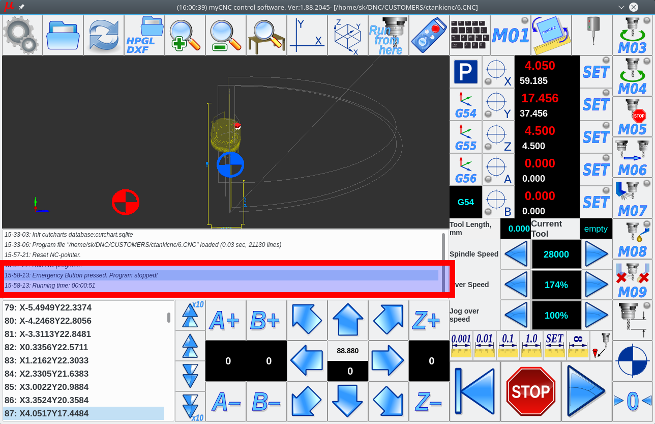
If Emergency button Alarm is triggered, the myCNC software stops running any Motion program or Jogging and Run PLC Handler for Emergency alarm - “EST.plc” PLC procedure. “Emergency button pressed. Program stopped!” message will be shown in the messages list
A user can define any behaviour for Emergency Stop event like -
- Power off servo-drivers
- Power off Spindle/Plasma power source
- Switch Off coolant, mist, air
- etc.
PLC procedure “EST.plc” is available in PLC Builder/Hardware PLC
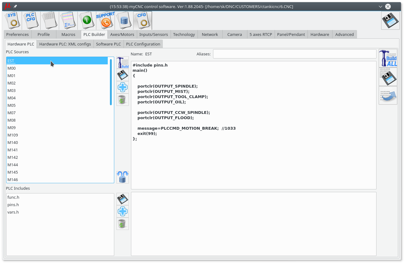
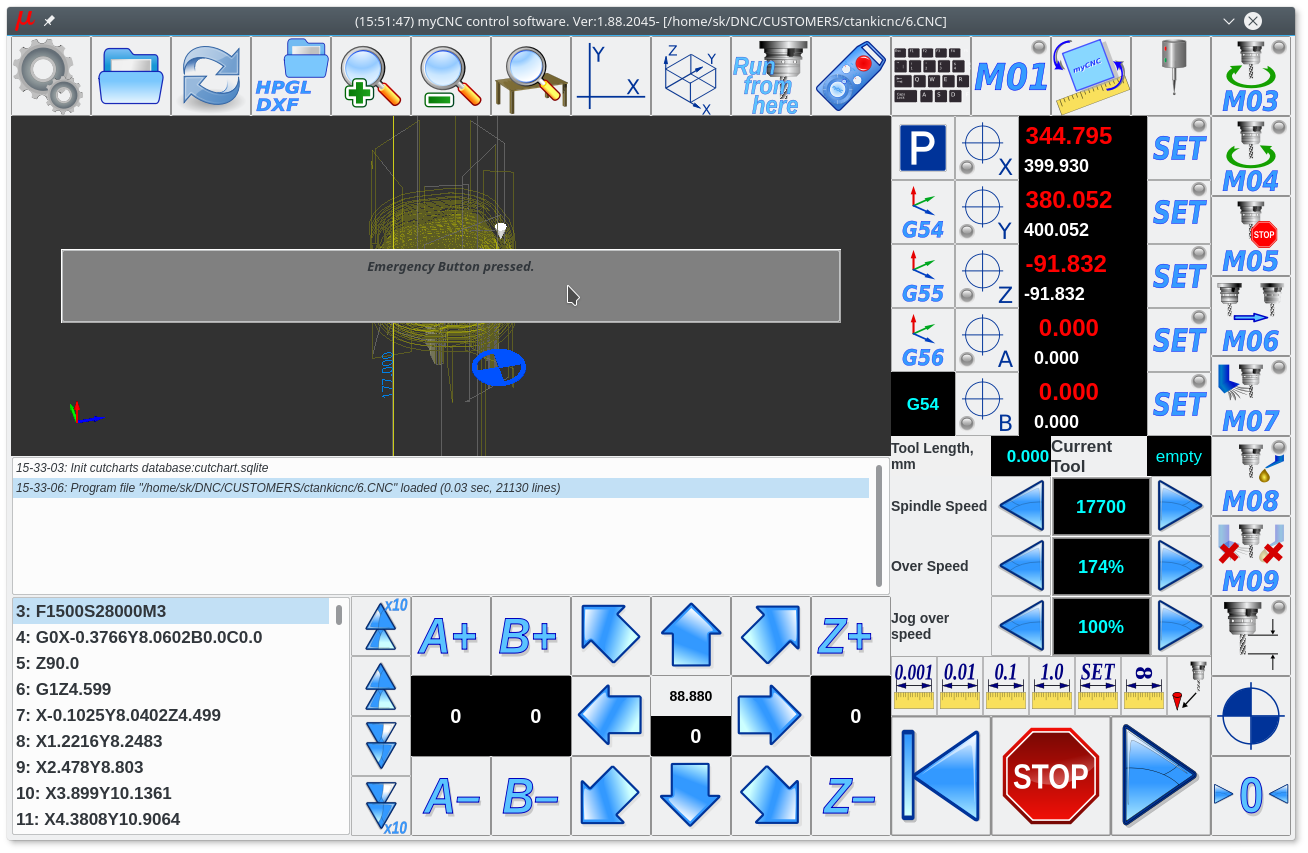
If Emergency button activated, all further Job running, or jogging will be locked.
“Emergency button pressed.” message will be shown on the main screen
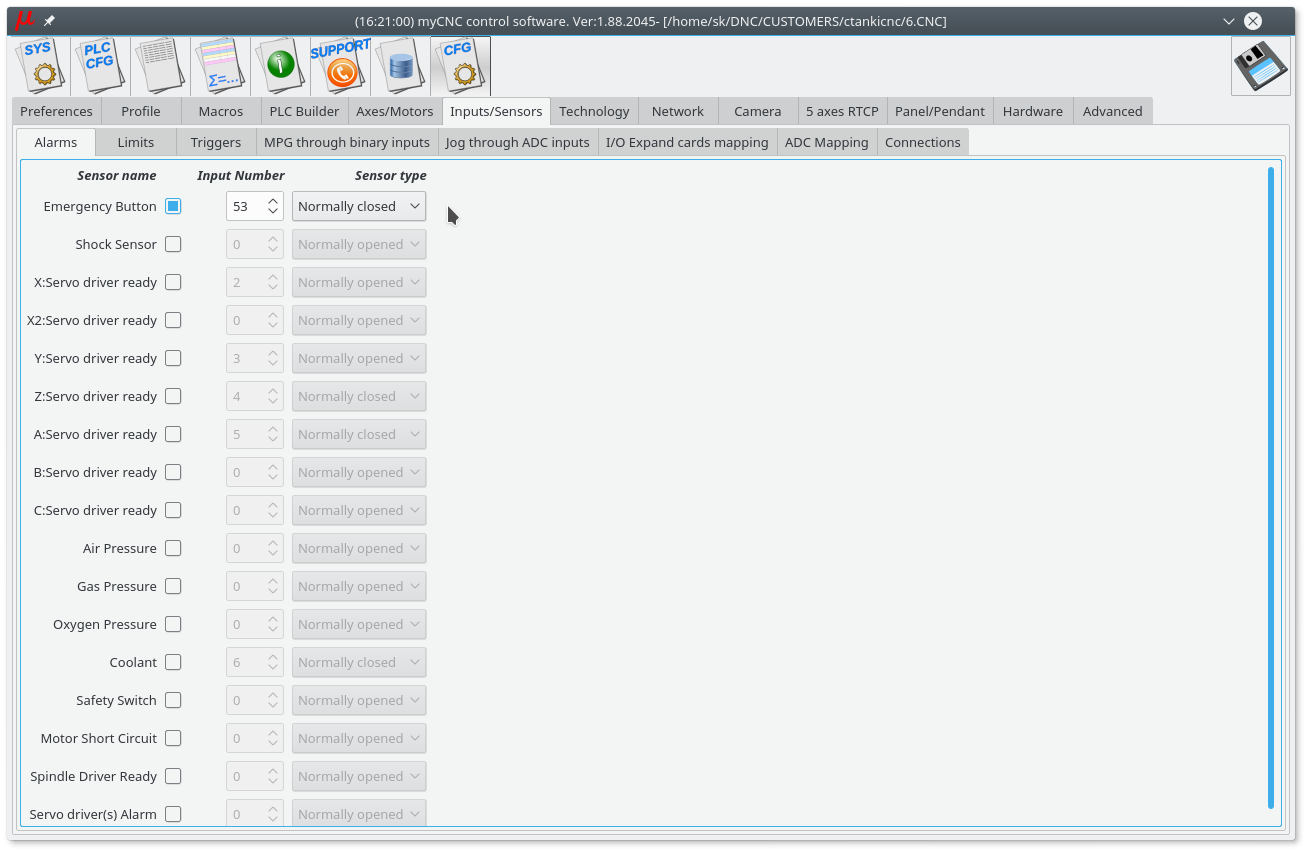
Example of Emergency button configuration is shown in a picture below
- Emergency button is enabled
- Binary input #53 is used as an Emergency key
- Emergency button is Normally closed, an Emergency event will be activated if the button is open
X-alarms
A more flexible alarm system, currently under development. This setting is recommended for users with unconventional cutting setups (such as complex plasma cutting machines with multiple sensors).
X-alarms allow to select the Input Number, the Type of input (normally open or closed), the process that the alarm triggering will be blocking (jog, job, PLC, or a combination of the three), as well as the Hardware/Software PLC Handlers which are summoned whenever the alarm is triggered. Due to being able to create unique PLC procedures, this alarm system can be customized to a much higher degree than the current alarm system which mostly deals with simple usercases.
As the system is currently under development, not all features are yet present or behave correctly. Stay tuned for further updates.
Limits
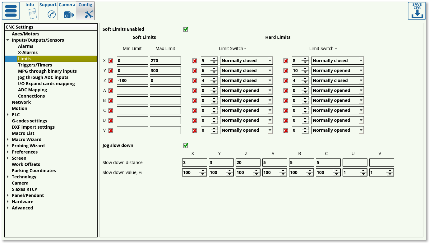
To configure the software limits:
- Check the “Soft Limits Enabled” checkbox
- Set ON the checkboxes for each axis you'd like to enable limits for
- Set the Minimum and Maximum range for each axis
- Press the “Save” button to save the settings
It is also possible to reduce the jog speed near the limits to prevent an abrupt stop when the limit is reached by the machine. If the operator moves the machine towards the software limit, the jog speed will be reduced beginning at a set distance from limit to a given value (in % of normal jog speed). To enable this option:
- Set “Jog slow down” checkbox
- For each axis, indicate:
- “Slow down distance” - the distance from the software limit when jog speed will begin to slow down
- “Slow down value, %” - Slow Jog speed (in % of normal jog speed)
- Press “Save” button to save the settings
For example:
Slow distance = 50, Slow value= 20%
If the operator moves the machine towards the software limit and distance to the limit is less than 50mm, jog speed will be 5 times less than the normal jog speed (20%)
Slow distance = 10, Slow value= 100%
No reduction in speed (because the slow jog value is 100% of the regular jog speed)
Besides having general software limits, hardware limits can also be configured in myCNC software. This is done by using a switch for the negative and positive direction of each axis which can be reserved within the myCNC software. Any switch can be enabled, and then assigned to any of CNC control board binary input and configured as “Normally Open” or “Normally Closed”. To enable the hardware limits for any selected axis:
- Choose the axis (X, Y, Z, A, B, C) and side (positive or negative) and set the respective checkbox to ON
- Set the input number for any of the switches connected
- Choose the sensor type to either be Normally Closed or Normally Open to specify the default behaviour of the switch
- Press the “Save” button to save your settings
Triggers/Timers
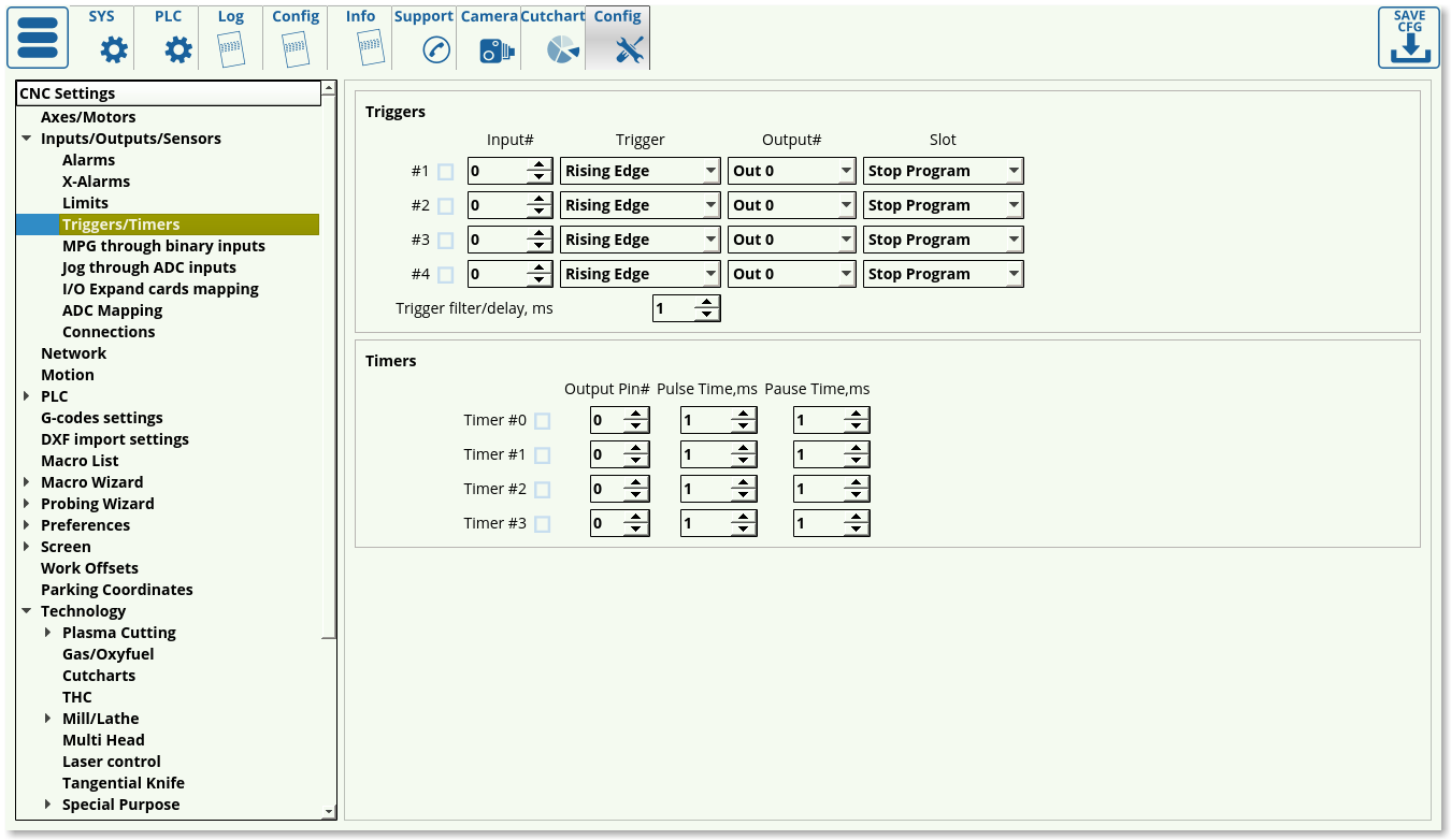
Triggers allow the software to interpret the sensor data depending on the sensor behaviour or the current position in the control program. The settings that can be assigned to the triggers are the following:
- Enabled/disabled toggle to specify whether this particular trigger is on/off.
- Input number to indicate which particular input the trigger is bound to.
- Trigger behaviour (rising/falling edge). The trigger does not check for the actual status of the sensor, but rather for the change in status. This way, if rising edge is specified, the trigger will be initiated when the sensor goes from OFF to ON (rising), and similarly, the trigger will be prompted if the falling edge has been specified when the sensor changes from ON to OFF.
- Output number specifies which output port is bound to the trigger prompt. This feature remains from the earlier versions of the software.
- Slot specifies the result of the trigger being prompted. Usually, the Stop Program option is chosen, however custom trigger responses can be written as PLC commands (such as TRIG04)
Timers serve as a way to use the controller rather than the computer for timing tasks. The following settings can be specified:
- Enabled/disabled toggle.
- Output pin number to specify which pin is bound to the timer
- Pulse time, in order to set how long the process tied to the output pin (such as a coolant system) will be ON
- Pause time, in order to set how long this process will be OFF
MPG through binary inputs
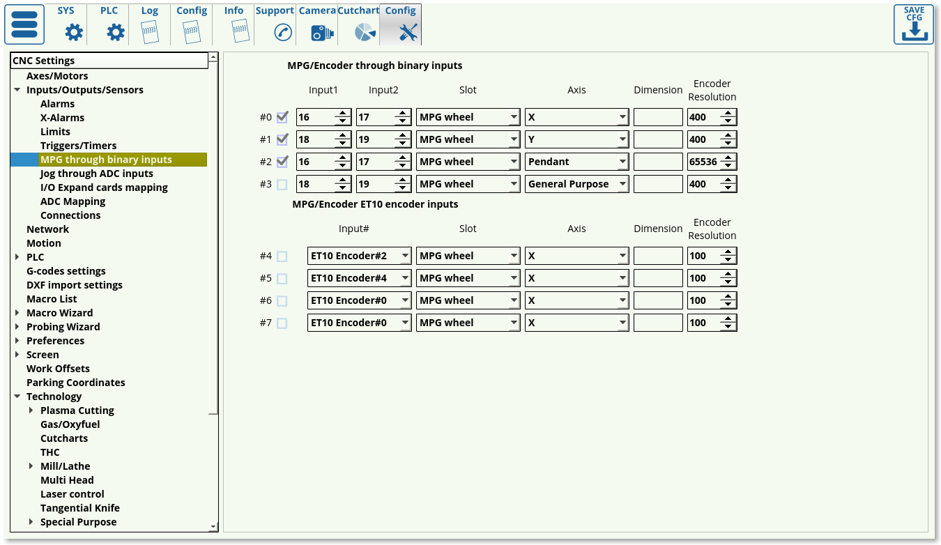 These settings allow the user to set up the manual pulse generator behaviour. The following settings can be modified:
- Enabled/disabled toggle for each MPG
- Input ports number (2 ports needed for an MPG).
- Slot can be changed between MPG (to move the spindle around), THC/Z axis offset for manual control of the z-axis during torch height control, or Spindle Sync to synchronize the vertical z-axis movement and the rotation of the spindle.
- Encoder resolution: number of encoder markings per rotation * number of impulses per marking
Jog through ADC inputs
This function is useful to set up a joystick in order to regulate the speed at which the machine's working tool moves through analog means, allowing for more granular controls.
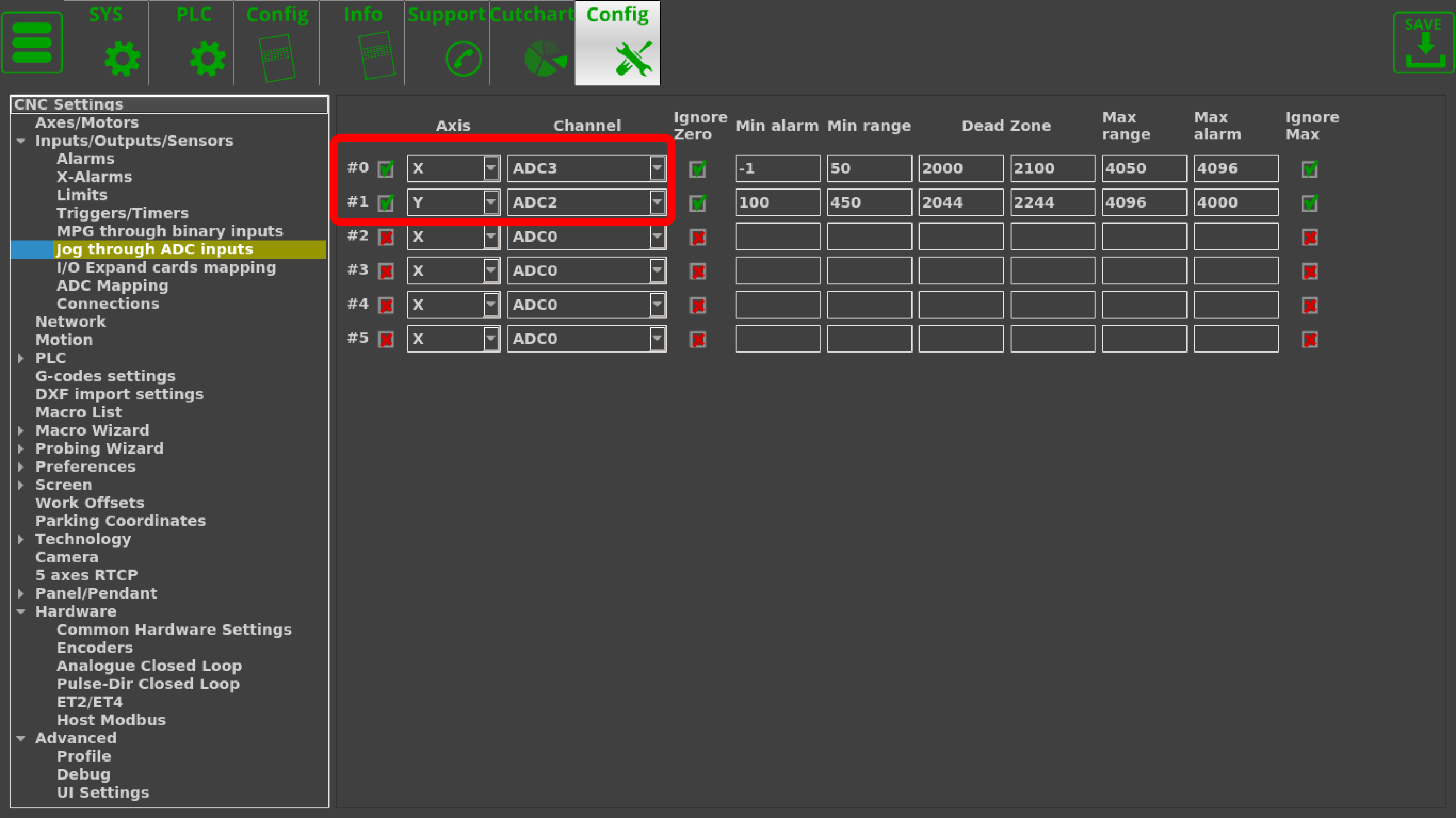
In order to do so, go to CNC Settings > Config > Inputs/Outputs/Sensors > Jog through ADC inputs. The following screen will be presented to you:
On this screen, we can set up the joystick inputs to adhere to the physical configuration and specifications of the joystick.
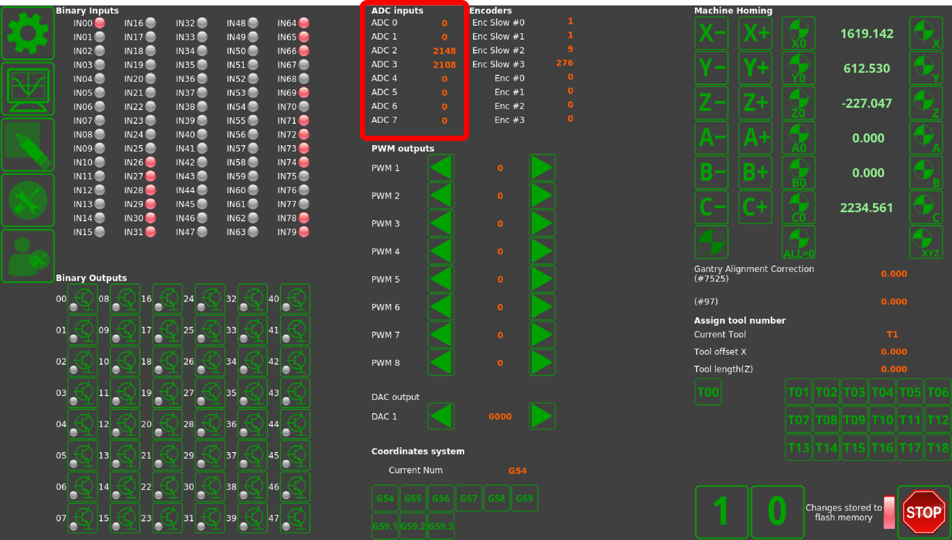
After connecting the joystick to the ADC ports of the controller, we can open the System Diagnostics window to check the actual ADC inputs.
While on the system diagnostics screen, move the joystick around to check which axis corresponds to which ADC input channel. In this example, ADC2 corresponds to the y-axis, while ADC3 corresponds to the x-axis movements of the joystick. These values are inputted back on the Settings screen:
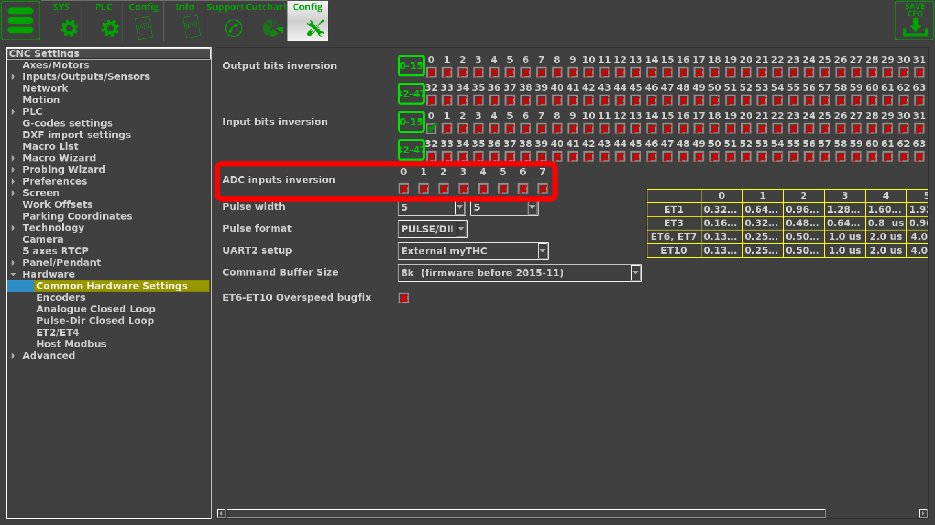
NOTE: If the axes for the joystick need to be inverted for any reason, this can be done in Settings > Config > Hardware > Common Hardware Settings
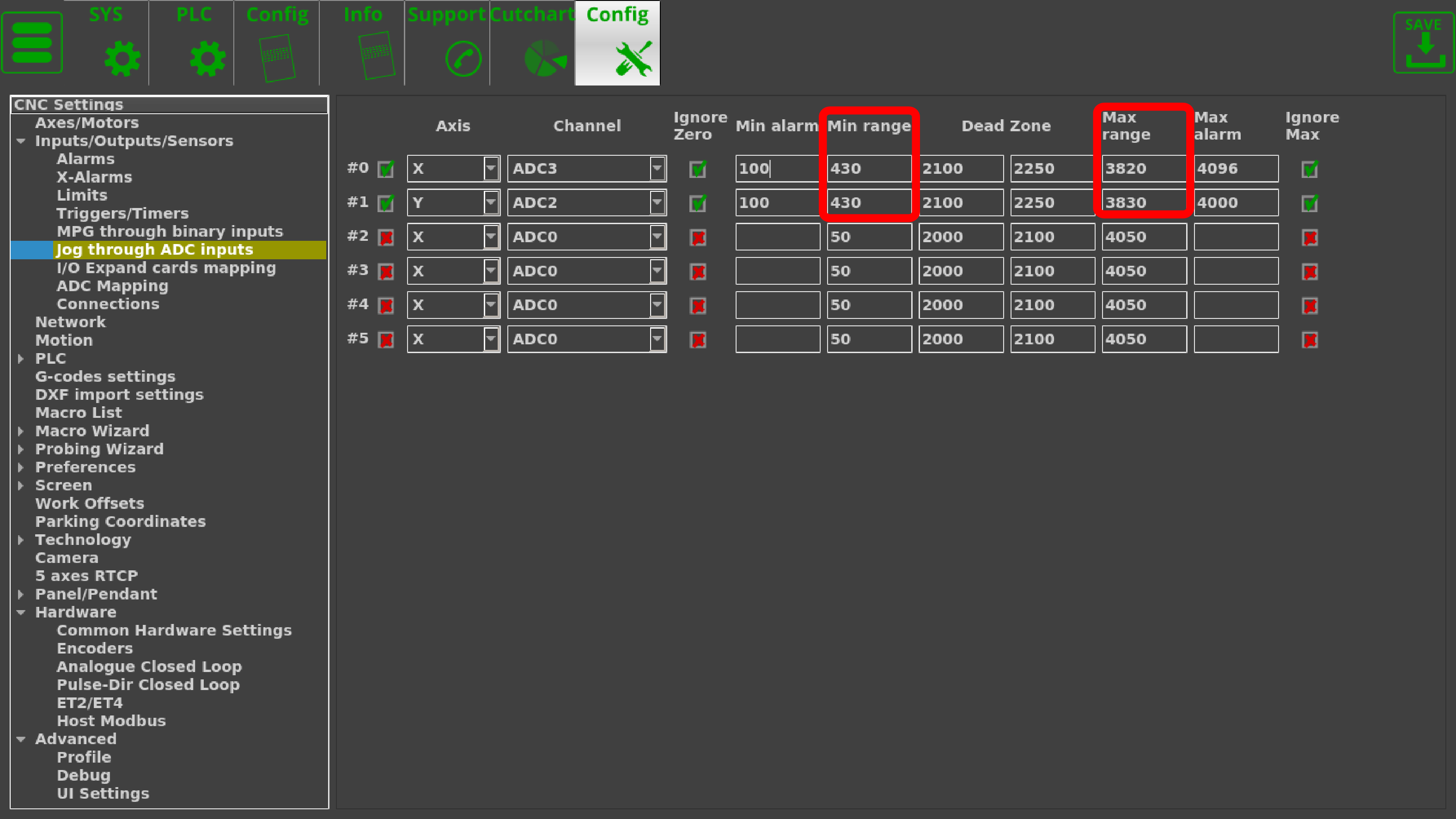
By moving the joystick the furthest it can go in all directions and noting the maximum and the minimum values, those can be set as the Max and Min range in settings. In this example, the joystick Min Range is equal to roughly 430 for both the x- and y-axis inputs, and is around 3820 for the Max Range of the x-axis and 3830 for the Max Range of the y-axis:
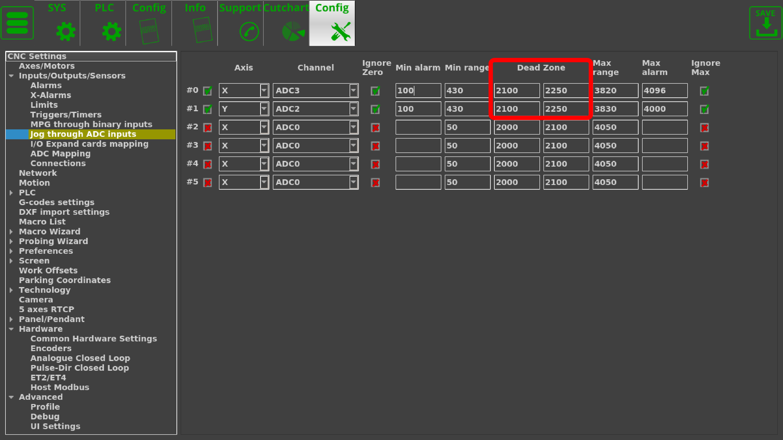
The Dead Zone is set to be from 2100 to 2150 for the joystick used in this example, as this is taken to be the zero position by letting the joystick return to its center. This value has a range so that small accidental movements of the joystick do not trigger the movement of the machine:
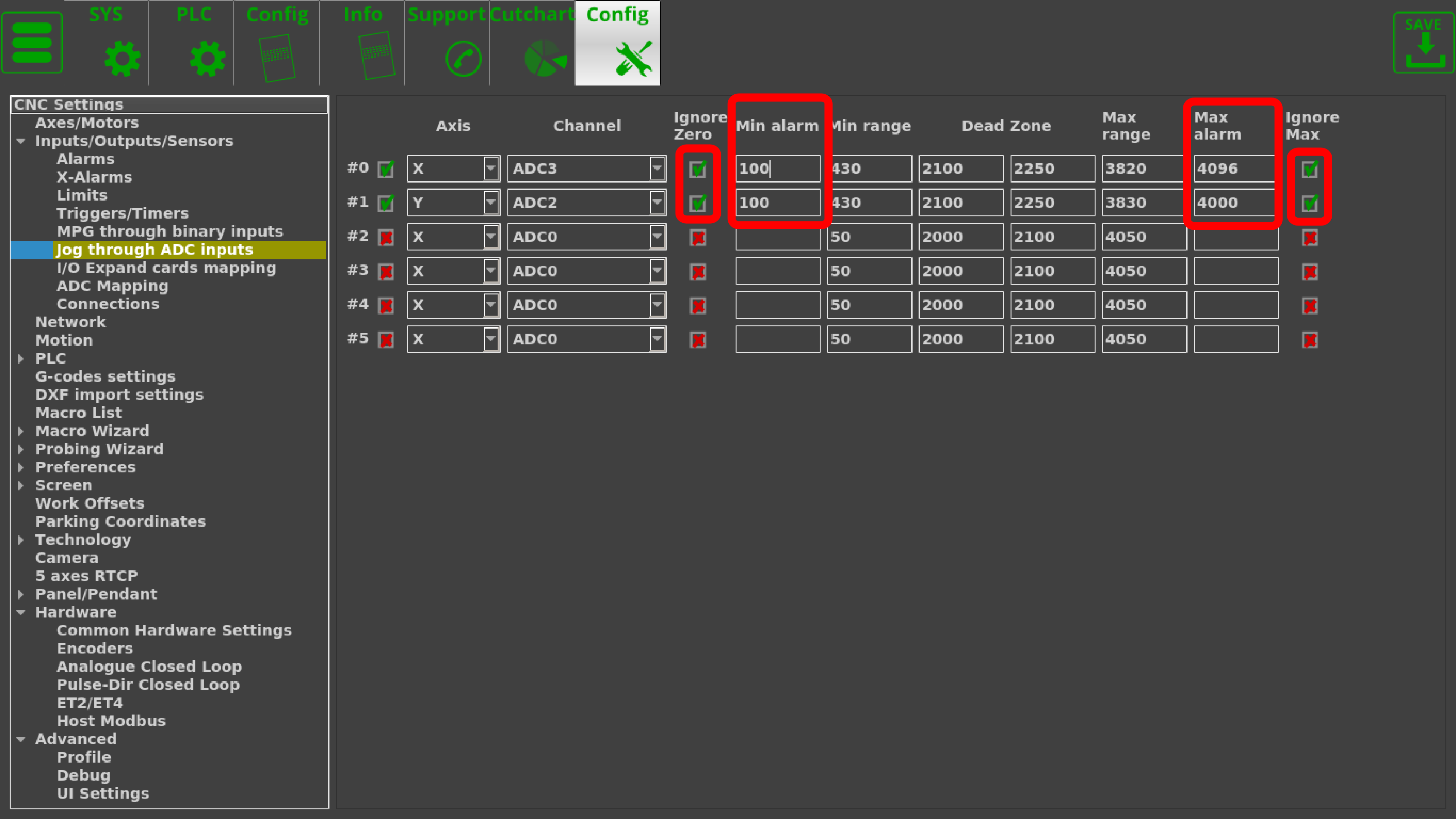
As this joystick does not drop to zero for its minimum range of inputs, it allows us to set up a failsafe in case the joystick is accidentally unplugged. In order to do so, both checkmarks for the Ignore Zero and the Ignore Max have been switched to green, and the Min Alarm and Max Alarm have been set to be slightly outside the Min and Max Ranges (however, the Min Alarm is ALWAYS set to be above zero in this case):
NOTE: Not all joystick controllers allow to set the failsafe Min Alarm properly.
Please consult your joystick manual to find out if the input values do not drop to zero
so that the failsafe can be set up correctly.
The full settings window then looks as follows:
I/O Expand cards mapping
ADC mapping
Connections
Network
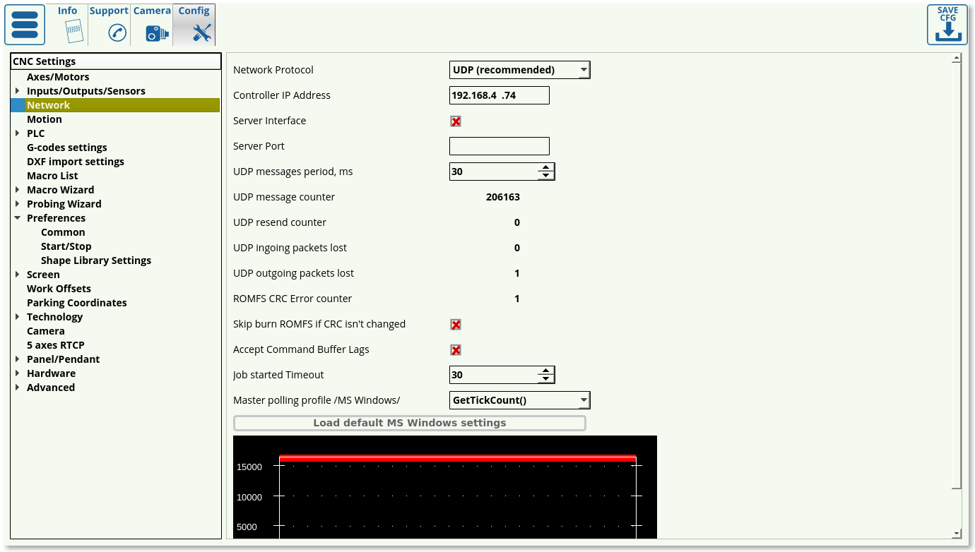
The Network tab is designed to help the user set up the connection with the controller. Upon opening the tab, you are presented with the following window:
- UDP is recommended as the network protocol, as TCP/IP is not used on the more recent myCNC controllers, and the Simulator mode is only able to perform simple tasks such as loading the program
- Controller IP Address specifies the IP address that the myCNC software will use to connect to the controller. Note that this address must be unique and different from your computer address for the connection setup to succeed.
- Server Interface and Server Port are used when it is necessary to connect to the program remotely. These can be disabled if there is no need for a remote connection.
- The UPD message period specifies the amount of time between each consecutive message sent to the controller. This is set to be 30 ms on Linux and 100 ms on Windows machines (which can be loaded using the “Load Default MS Windows Settings” button).
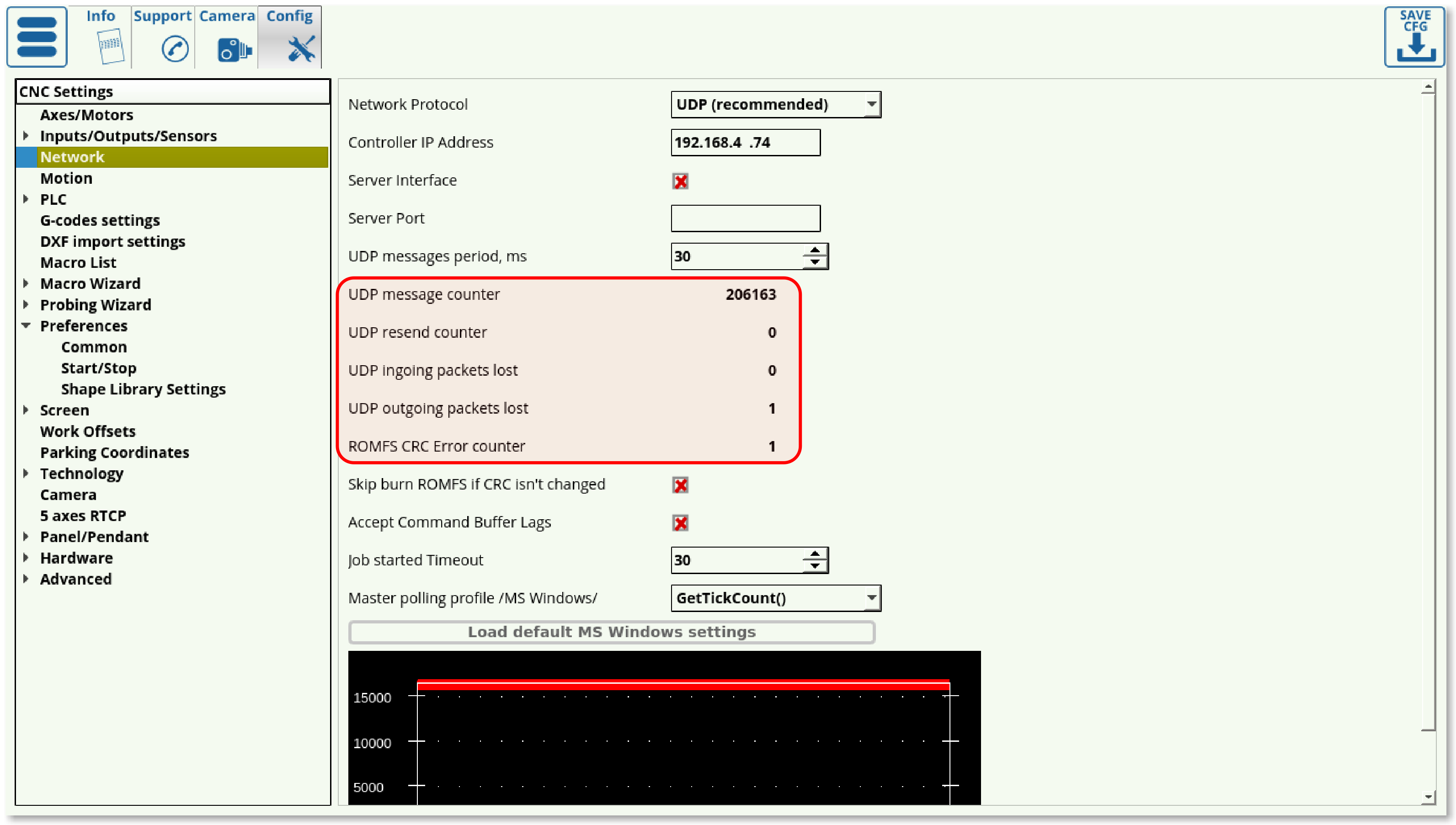
- The message/packets counters allow for quick diagnostics when using myCNC software. These indicate the number of messages sent, messages resent, as well as incoming and outgoing packets lost. Note that single digit packet loss is normal when first turning the controller/software on and as the connection is being set up since the message number that the controller expects will differ from the once sent from the myCNC software after restart. However, it is recommended to watch the packet loss number over some working time period (half-hour to an hour) to see if there is a constant packet loss occurring after the software setup has been completed. If continuous packet loss occurs, it indicates problems in the connection between the host computer running myCNC software and the controller.
- The Skip Burn ROMFS toggle allows to skip writing PLC onto the controller every time a new session is started. This can allow to reduce the start up time of the myCNC controller if no changes to PLC are planned to be introduced.
- Accept Command Buffer Lags toggles the acceptance of lagging commands that are sent to the controller despite the delay indicated in the command buffer window below. This is usually done when the number of commands per second is very large (in the hundreds/thousands), and can lead to unexpected jerks of the machine due to sudden speed changes. This setting is recommended to be used in an experimental fashion.
- Job started Timeout specifies the time (in messages sent) between the signal for job start and the maximum allowable point at which the controller has to send a signal back to the host computer to confirm that the job has indeed started. This is set to be 15 by default - setting it much lower will result in the controller not having enough time to send a response signal to the computer, while setting it much higher might result in the computer taking much longer to process each individual user command.
- Master polling profile specifies the network connection behaviour in MS Windows setups. This is set to the GetTickCount() option, and should not be changed unless required.
- Load Default Settings buttons allow the user to load the default network configuration for MS Windows and Linux machines in one click. The only difference between the MS Windows and Linux configurations is in UDP Messages Period field, with 100 and 30 ms respectively.
Motion
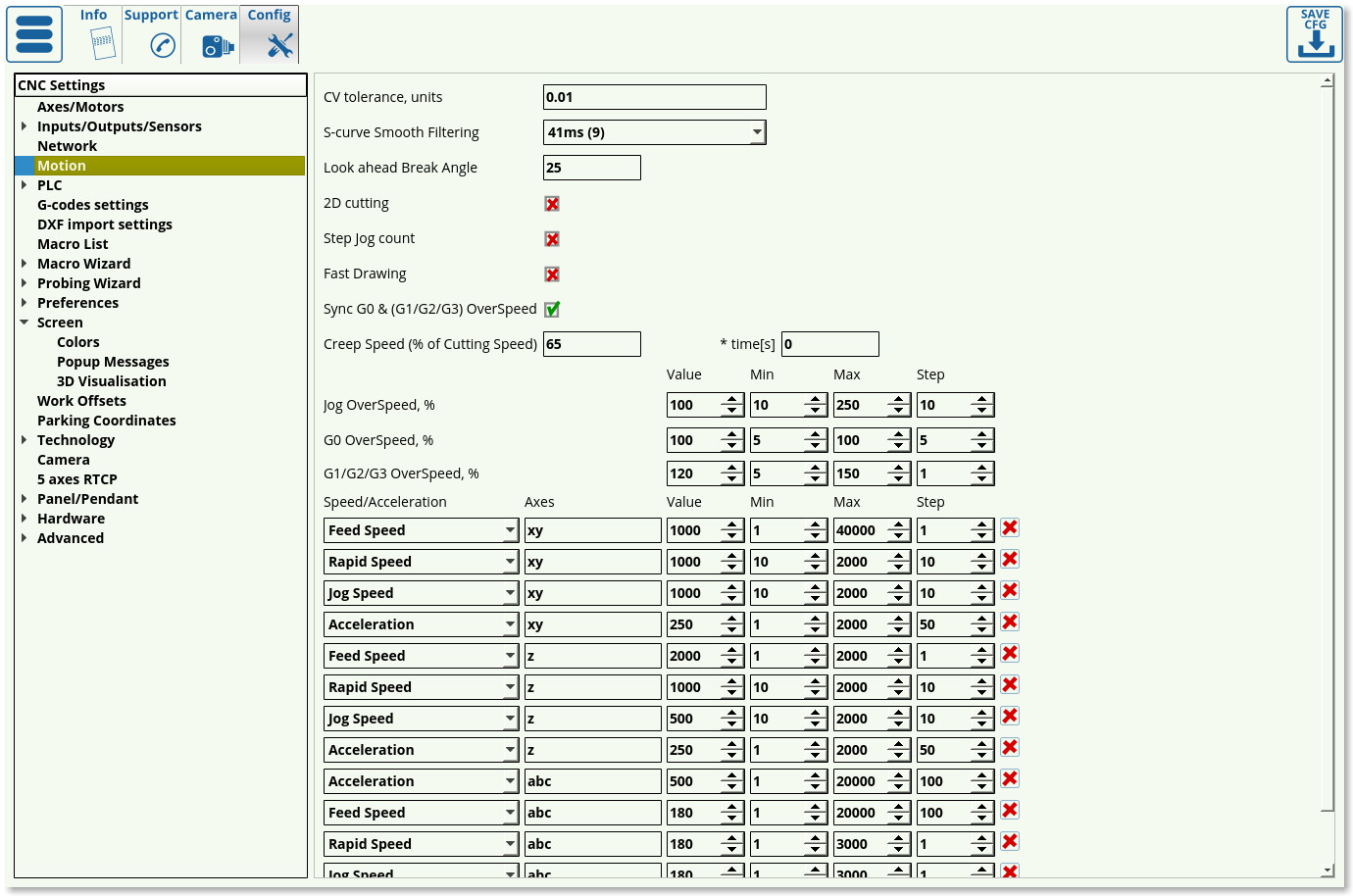
Upon opening the Motion tab in Settings, you are presented with the following window:
The following settings can be edited in the Motion tab:
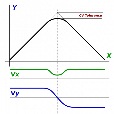
- CV Tolerance signifies the amount of “smoothing” on corners that is allowed at maximum, and is done in order to make the program go through corners faster instead of stopping at every sharp corner. As seen in the image below, the tolerance describes the distance from the “ideal” corner to the actual tip of the corner that the machine will produce.
- S-curve smooth filtering specifies the time the controller gives the machine to adjust its acceleration during sharp turns. A larger value allows for a larger impulse time, resulting in reduced stress and shocks to the machine hardware. 41ms is recommended.
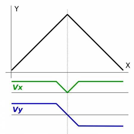
- Look Ahead Break Angle - if the angle is larger than this, the machine will stop at corner completely in order to allow for a sharper cut. An example of such a cut is shown in the image below:
- 2D Cutting is used on plasma/gas machines which lack a configurable z-axis. This option is turned OFF by default.
- Step-jog count specifies whether the user wants the machine to monitor the inputs sent to it as it is already moving or not. If selected, the machine will count however many signals are sent to it even if it is moving already, if not selected then the machine will ignore other signals until it has completed its initial movement.
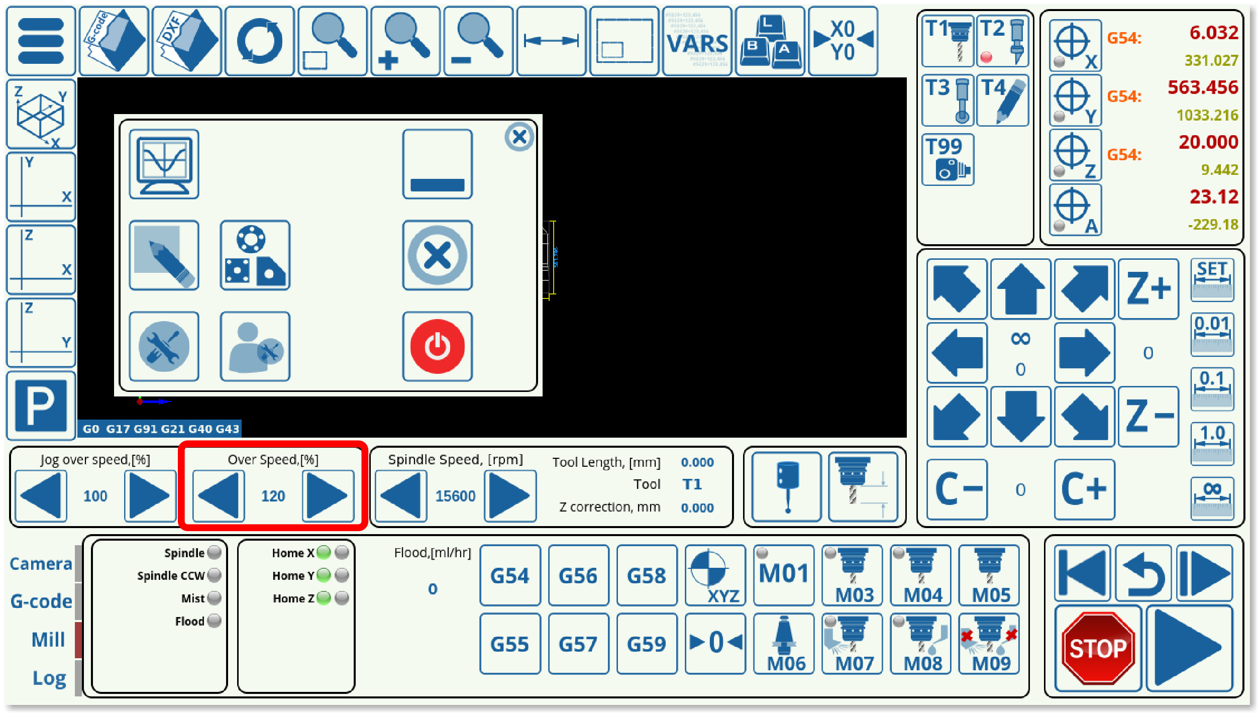
- Sync G0 & (G1, G2, G3) Overspeed allows the user to sync the rapid and cutting speeds, allowing the user to use one set of buttons (shown in the screenshot below) to change them at the same time.
- Creep Speed specifies the speed of the machine after it begins to cut into the working material. It is advisable to set it to be lower than the actual working speed for a small portion of time at the start of the cut. This time is specified in seconds.
- Jog, G0 and G1, G2, G3 Overspeeds signify the value by which the speed is higher/lower than the one specified by the running program. This is useful so as to be able to change the speeds on the fly. The max and min values specify the speed boundaries, so if a certain boundary needs to be imposed, the operator cannot accidentally go over or under the max/min speed limits by using the sliders on the main screen. The step meanwhile indicates the increments by which the speed values change when the operator clicks the main screen sliders.
- Speed/Acceleration table allows the user to edit the values for Feed/Rapid/Jog speeds and accelerations of different axes, as well as the speed/acceleration limits on these axes. Note that the axes can be coupled, with settings for the xy-axes being changed together in the setup shown in this example.
PLC
Hardware PLC
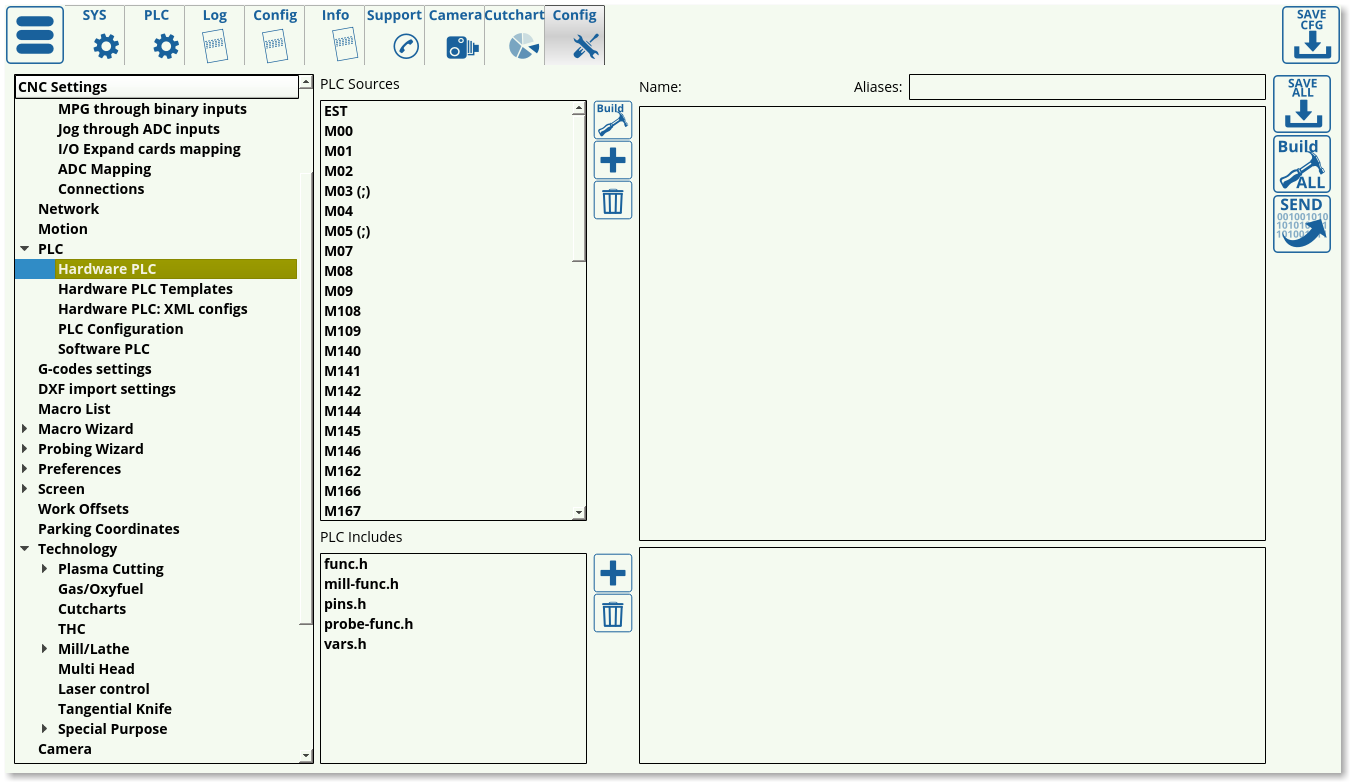
This list presents the available hardware PLC macros, with the ability to add, delete and edit the individual macros as required.
Hardware PLC Templates
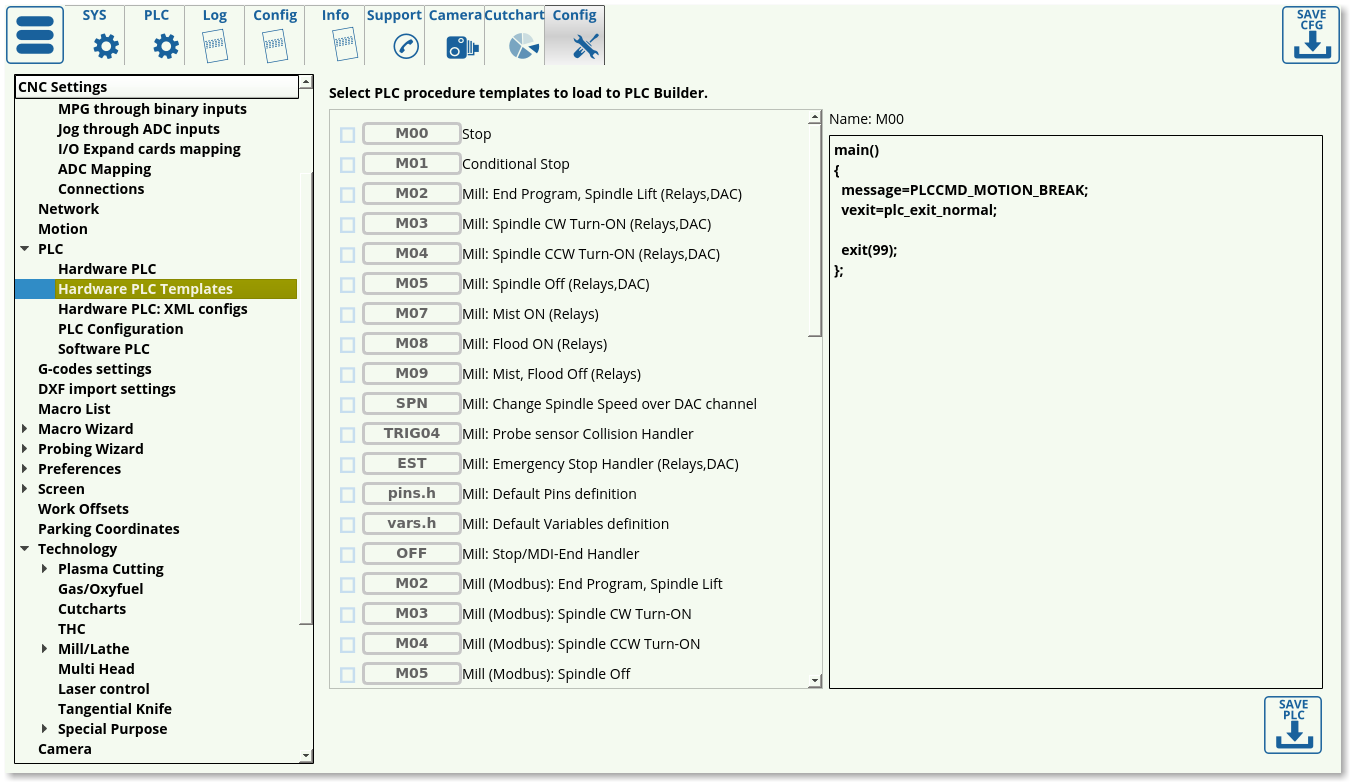 This list presents the available templates that are commonly used in some CNC setups, including macros such as Emergency Stop Handler, the CNC Vision camera macros, etc. This page allows the user to load the commonly used macros into the myCNC Hardware PLC list even if the original macros have been changed/removed.
Hardware PLC: XML configs
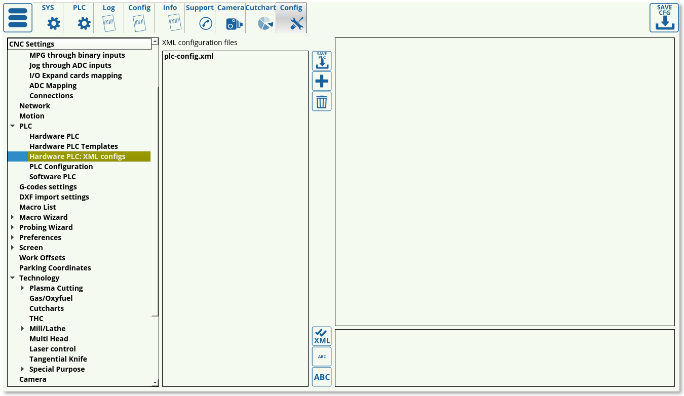 XML configs list currently consists of the plc-config.xml file which serves to connect the macros and the screen elements for these macros by assigning and storing proper variable names. This file should not be edited unless strictly necessary.
PLC Configuration
 The PLC configuration window allows the user to switch to an old-style precompiled ROMFS PLC disk if necessary instead of the more recent Internal PLC Builder setup.
Software PLC
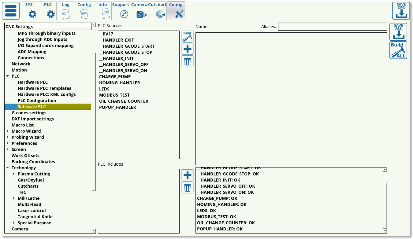 The Software PLC list consists of the PLC macros such as the Oil Change Counter and the Popup Handler which are done on the software side, rather than the hardware side.
G-codes settings
The G-code settings allow the user to fine-tune the preferences for g-code operations.
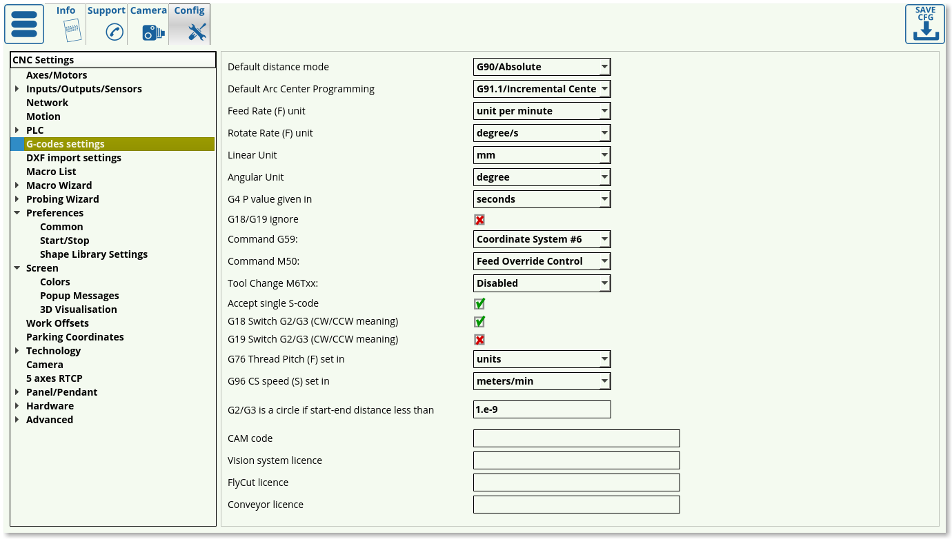
- Default distance mode can be switched between G90 (absolute) and G91 (incremental) modes to be used as default when loading the program
- Default Arc Center Programming can be G91.1 (incremental center) or G90.1 (absolute center)
- Feed rate units can be switched between units per minute and units per second
- Linear and angular units are set to be in mm/inches and degrees/radians/gradians respectively (usually set to be in mm/degrees)
- G4 P Value is the pause value given to be in seconds/milliseconds
- G18/G19 ignore toggle indicates whether to ignore YZ and ZX planes while drawing and only use the XY plane
- Command G59 is set to switch the coordinate system to Coordinate System #6 by default. However, if Hypertherm systems are used, Command G59 can be switched to comply with the Hypertherm command style.
- Similarly, Command M50 can be assigned to THC OFF, Feed Override Control or Hypertherm style of commands.
- Tool Change toggles whether the user can set up the tool change from the main screen of myCNC software. Turn ON to enable tool switching.
- Accept single S-code allows the machine to accept single commands for spindle speed changes on the fly. Not applicable to every configuration.
- G18/G19 Switch re-orients the arcs from clockwise to counterclockwise rotation when drawing. Depending on the CAM software used, different configurations of this setting are required.
- For example, in this particular program, G19 Switch is ON, G18 Switch is OFF. As can be seen, the arcs are not drawn correctly:
- Having turned the G19 Switch OFF and the G18 Switch ON, the arcs are now drawn properly:
- G76 Thread Pitch can be specified to be set in the default units (defines as Linear Units earlier) or as mm/inches depending on the operator's needs.
- G96 CS speed is the constant speed setting which can be set to be in meters or feet per minute.
- In certain older CAM software packages, the start/end points of a circle do not coincide correctly, leaving a small gap inbetween the two points which should be directly superimposed. It is possible to disregard very small distance that would be otherwise present between these two points and assume that they are, in fact, the same point using the “G2/G3 is a circle setting”. This distance should be set to be small as to not create false positives of two points being otherwise not connected by an arc.
- CAM code, as well as the Vision system, Flycut and Conveyor licenses are also specified on the G-code page.
DXF import settings
The DXF import settings window looks as follows:
- The window at the top corresponds to the one seen by the user upon importing the DXF file. These technology settings can thus be edited both from this Config window and the DXF import window.
- Below it is the list with all the DXF layer names imported into myCNC. This allows the user to set default tools/priorities to the layer names used in the DXF file if the user so desires. This makes importing a large number of files easier if every layer name has already been standardizes in the illustration software used.
- The DXF Header and DXF footer allow the user to insert macros in the beginning and at the end of the entire DXF file, as opposed to the headers and footers for each particular technology on the Import screen which are only used for one particular tool.
- It is possible to Hide DXF Settings tabs in DXF Import if the user so desires by using the dedicated toggle. This will keep the DXF Settings tabs on this config page, but will remove it on the import screen
- DXF Scale and DXF Offset are direct copies of the settings on the Import screen and can be edited in either location
- Ellipses interpolation can be set to be by Lines or Arcs, depending on the usercase.
- Ellipse segments specify the number of segments into which the ellipses will be split
- DXF toolpath optimization toggle allows the myCNC software to optimize cut time by choosing the closest next cut as the program is running. This setting is usually left ON, however in case that the file you are importing already has a specified toolpath it can be toggled OFF.
- Contour direction is useful on mill/plasma machines which care about the clockwise/counter-clockwise direction with which the tool is cutting the material. It can be set to Original, CW, or CCW.
- Spline segments specifies the number of segments the splines are split into in order to create their linear approximation within the software.
- Each particular technology can be toggled on/off depending on whether the user wants to see each particular tab on the Import screen.
Macro List
Macro Wizard
Homing XYZABCUV
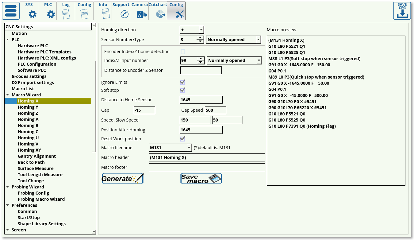 Homing settings are available for all the potential axes that are used by the myCNC software (X, Y, Z, A, B, C, U, V), as well as the XY-plane. In order to set up homing, the following settings are available:
- Homing direction. This is selected depending on where your sensor is located in relation to the working bit of the machine. If the machine will have to move in the negative x, y or z direction to find it, select -. If the machine will have to move in the positive x, y or z direction, select +.
- Select your sensor number (depending on how you have connected it) and its type (normally opened or normally closed).
- Choose your Limits behaviour in the Ignore Limits field. Set the checkmark to ON if the sensor you are using for homing is the same as the one you are using for your limits (most common case), and set it to OFF if you are using multiple sensors.
- The Soft Stop setting allows for a gradual stop after the sensor has been passed
- The Distance to Home Sensor has to be set up to be slightly higher than the maximum length that the working piece will have to travel to find the homing sensor
- Using the Gap setting, the user can add a gap between the sensor position and the new software Home position. The Gap Speed will describe the speed with which the machine moves between the sensor and the gap end
- Speed field specifies the speed at which the machine is moving during its initial movement towards the sensor. After the machine triggers the sensor, it starts to move back in order to find the precise spot at which the sensor has been triggered, at the Slow Speed.
- Position After Homing field specifies the value assigned to the position after the homing.
For a full guide on homing, please consult the QuickStart Homing Manual.
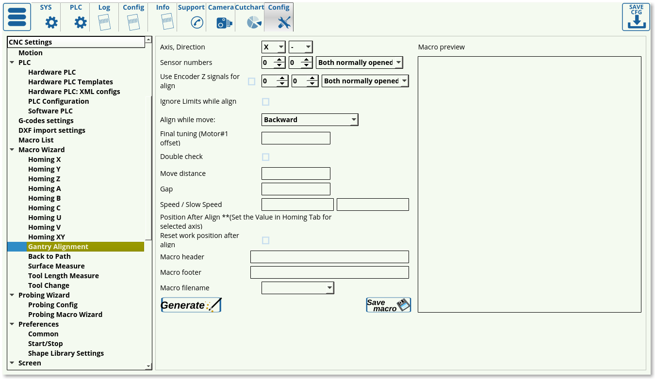
Gantry Alignment
Back to Path
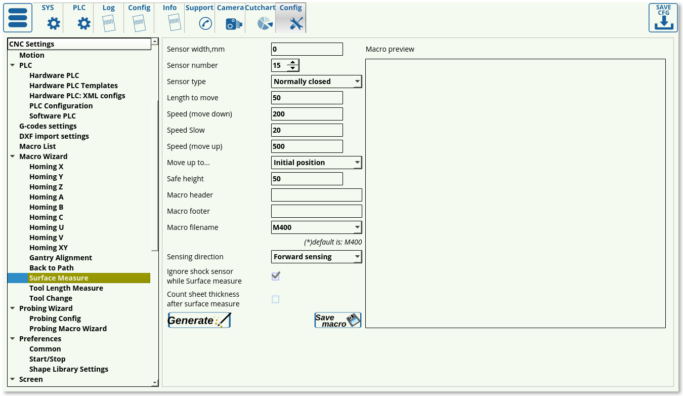
Surface Measure
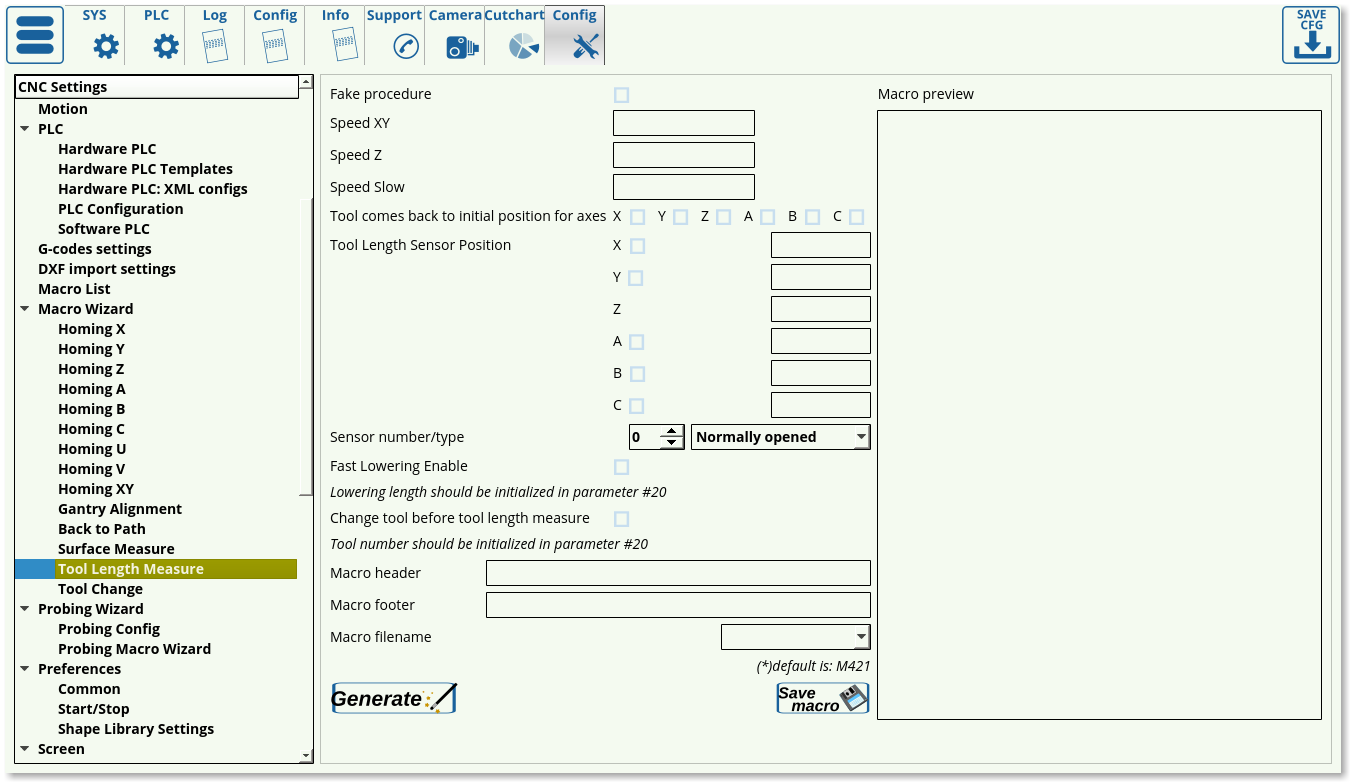
Tool Length Measure
Tool Change
Probing Wizard
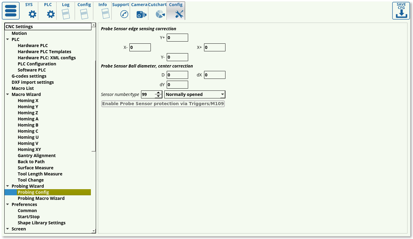
Probing Config
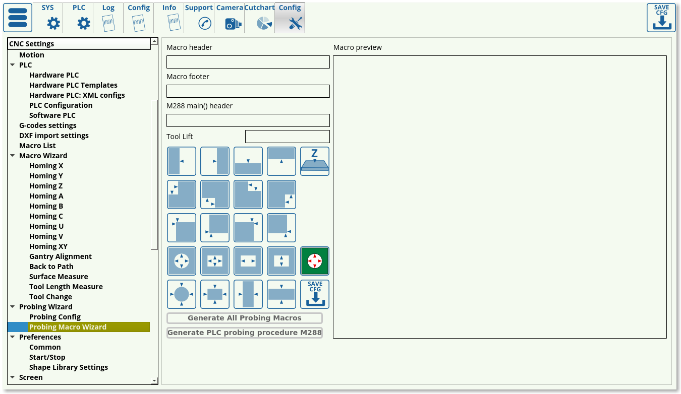
Probing Macro Wizard
Preferences
Common
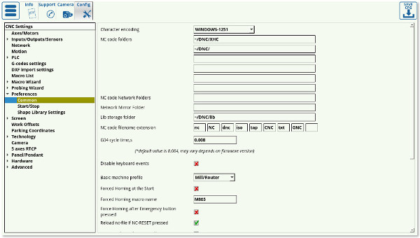
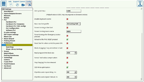
- Character Encoding - myCNC software uses Unicode Text encoding system. If input g-code files contain symbols encoded in other Encoding system, this system should be set in Character Encoding. combobox to show local symbols correctly in myCNC software
- NC code folders - In File Open Dialog and DXF Import Dialog, the myCNC software will search for nc-files in folders provided in this field. For example, if the NC code folders are set as “~/DNC” and “/media”, then only these folders will be available to open g-codes or dxf files.
- NC code network folders specify the network folders that the myCNC software will access to look for nc-files. The folder that myCNC will access will also be mirrored to one specified in the next field, Network Mirror Folder, to prevent issues in case of a poor network connection.
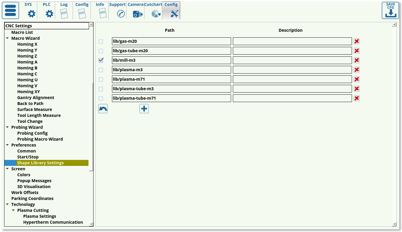
- Lib storage folder specifies the folder in which the library parts are stored on the computer.
- NC code filename extensions list the possible extensions that the software will allow the user to open. If an extension is not on the list, it can be added provided it can be read by the myCNC software.
- G04 cycle time marks the internal controller setting for time marking in order to properly synchronize the controller and the computer.
- The Disable keyboard Events setting allows to completely disable keyboard inputs, leaving only the touchscreen.
- The basic machine profile can be specified to be Mill/Router, Lathe, Cutting Table, or 3D Cutting Table, depending on the user's needs
- The Forced Homing at Start and the Forced Emergency Homing settings are used only in older versions of the software and will be deprecated in the upcoming myCNC software versions. The functions of these settings have been replaced by the HOMING_HANDLER from Software PLC.
- Reload nc-file if NC-RESET pressed toggles whether the full file is reloaded upon pressing the Return to Top button on the main software screen. The toggle is left ON by default.
- Reset tool number setting allows the user to reset the tool number after the controller has been turned off and on again. This is an experimental feature for only certain setups, and is not recommended by default.
- Block all jogging if any servodriver is faulty allows the machine to stop all movement if any of the motors indicates issues. Not recommended by default, since the user might still need to lift the part up using the z-axis motor even if both the x- and the y-axes motors fail.
- Read program first block size sets the size of the block of code that the computer will read at a time. This setting is not edited on most recent machines, and is kept at around 2000. If using an older host computer, this block size can be reduced.
- Forced tool radius compensation - by default, the computer checks the first block of code with the size specified in the field above, and then tries to locate tool radius compensation commands in that first block of code. If it has not located tool radius compensation, the computer will assume that the entire program is free of tool radius compensation, and will proceed without account for it, saving time. If, however, the user is aware that there is tool compensation at some point in the program that is further than the first code block size, the toggle for Forced Tool Radius Compensation can be turned ON. This will force the machine to account for tool radius compensation, however this will also significantly slow down the cutting process.
- Stop Step Jog if button released toggles the behaviour of the buttons which control the step jog. With the toggle OFF, every press will make the machine move, while with the toggle ON, the user will have to keep pressing the button until the movement has completed for additional safety.
- SSD Write Optimization toggle controls the program utilizing cache instead of writing to disk. This is turned ON by default.
- KSpingBox settings specify the behaviour of the control buttons on the main software screen. These settings are usually left to be at their default values unless changes are necessary.
Start/Stop
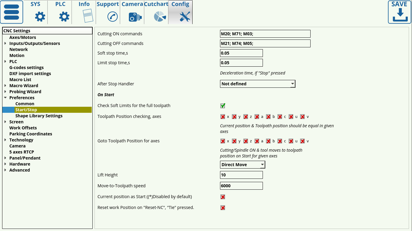
Consult the QuickStart Start/Stop Setup for a full overview of the Start/Stop features.
Shape Library Settings
Screen
Colors
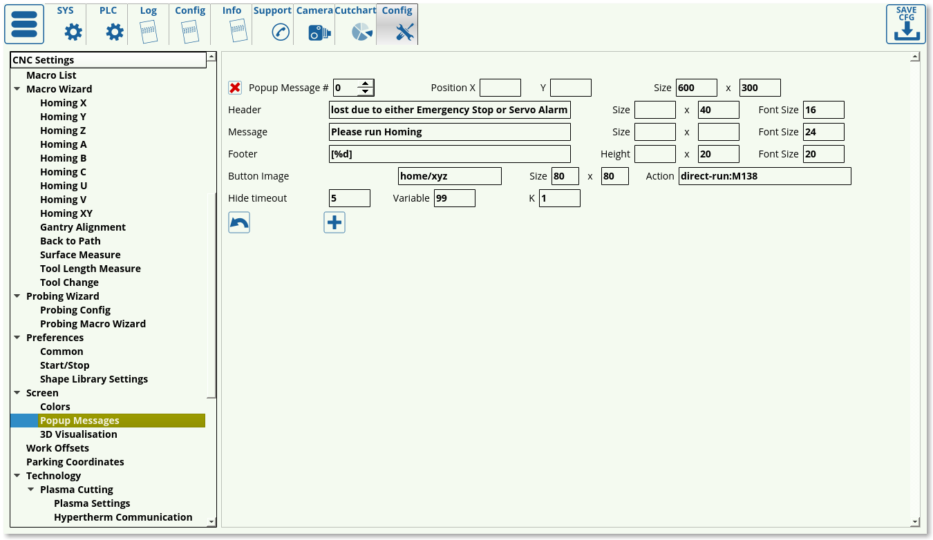
Popup Messages
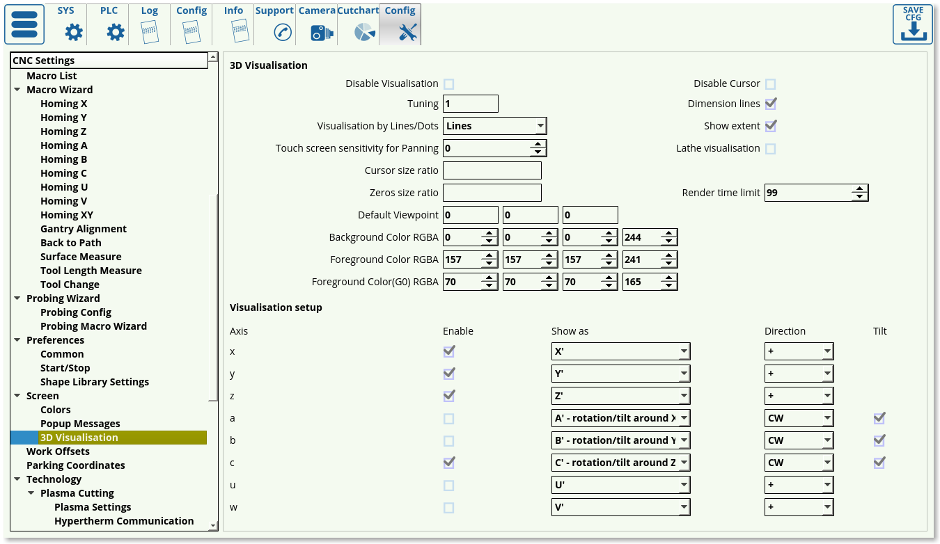
3D Visualization
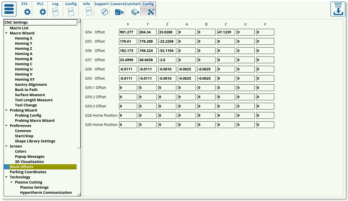
Work offsets
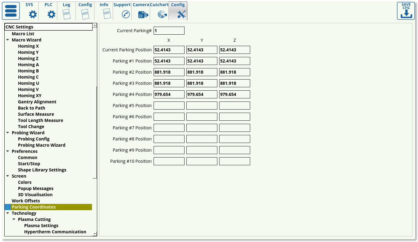
Parking coordinates
Technology
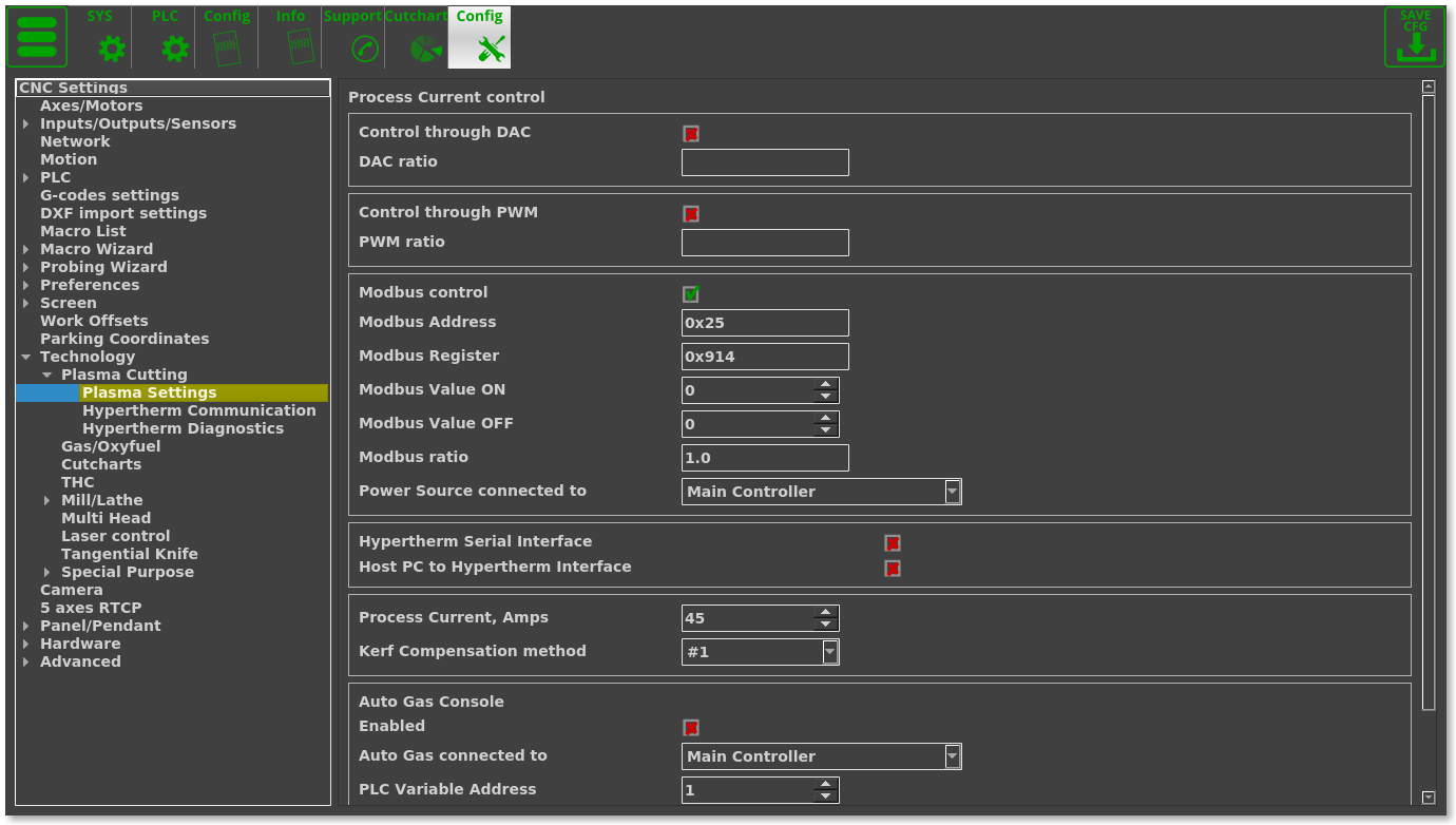
Plasma Cutting
Plasma Settings
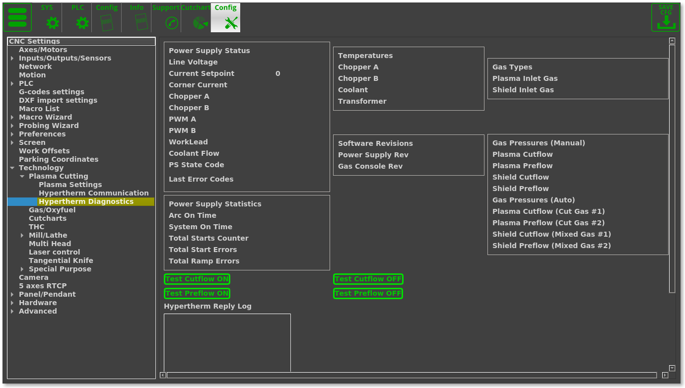
Hypertherm Communication
Hypertherm Diagnistics
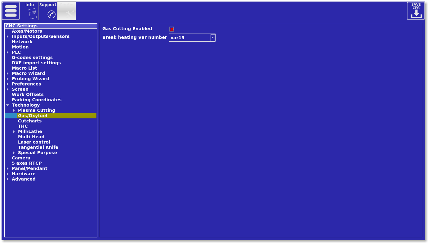
Gas/Oxyfuel
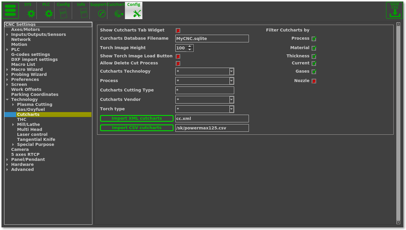
Cutcharts
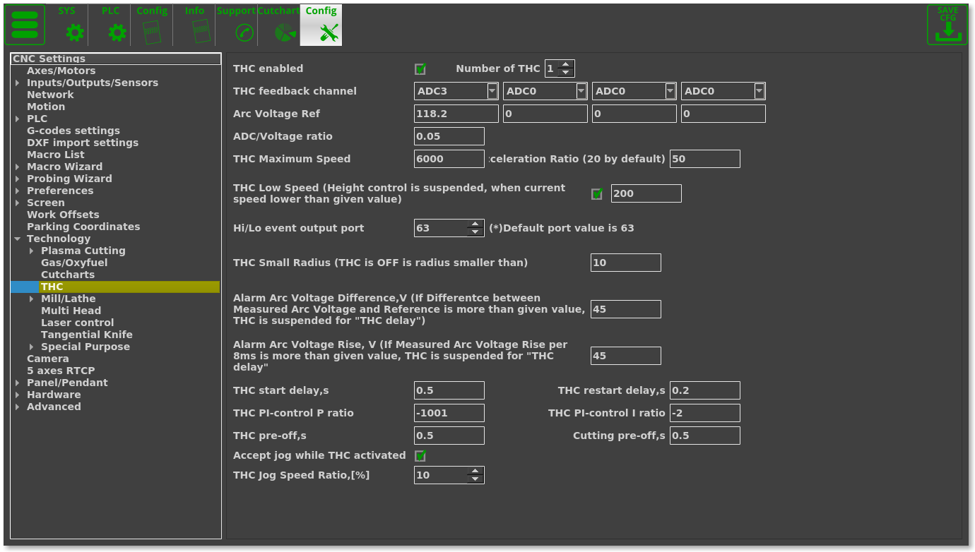
THC
Mill/Lathe
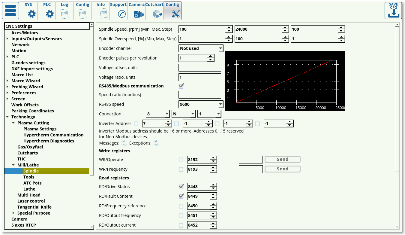
Spindle
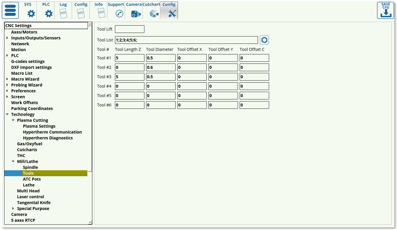
Tools
ATC Pots
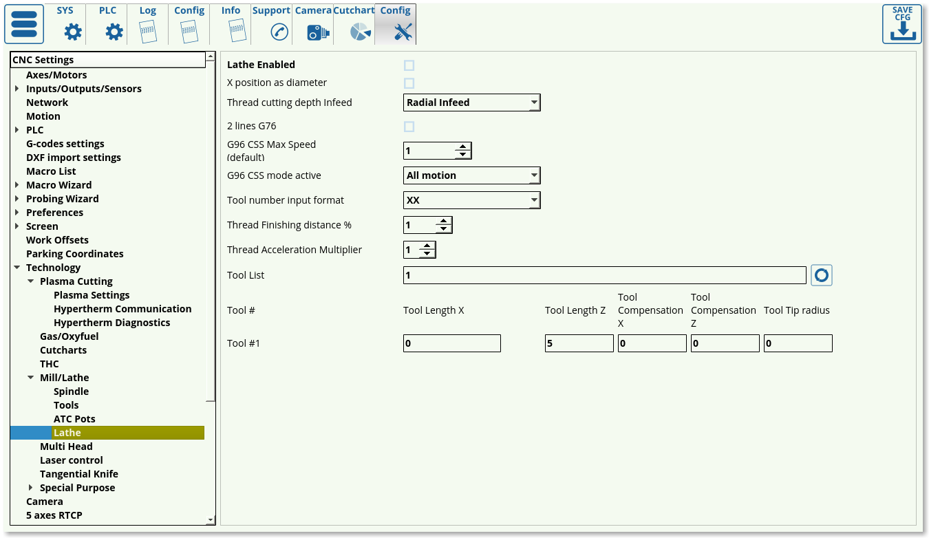
Lathe
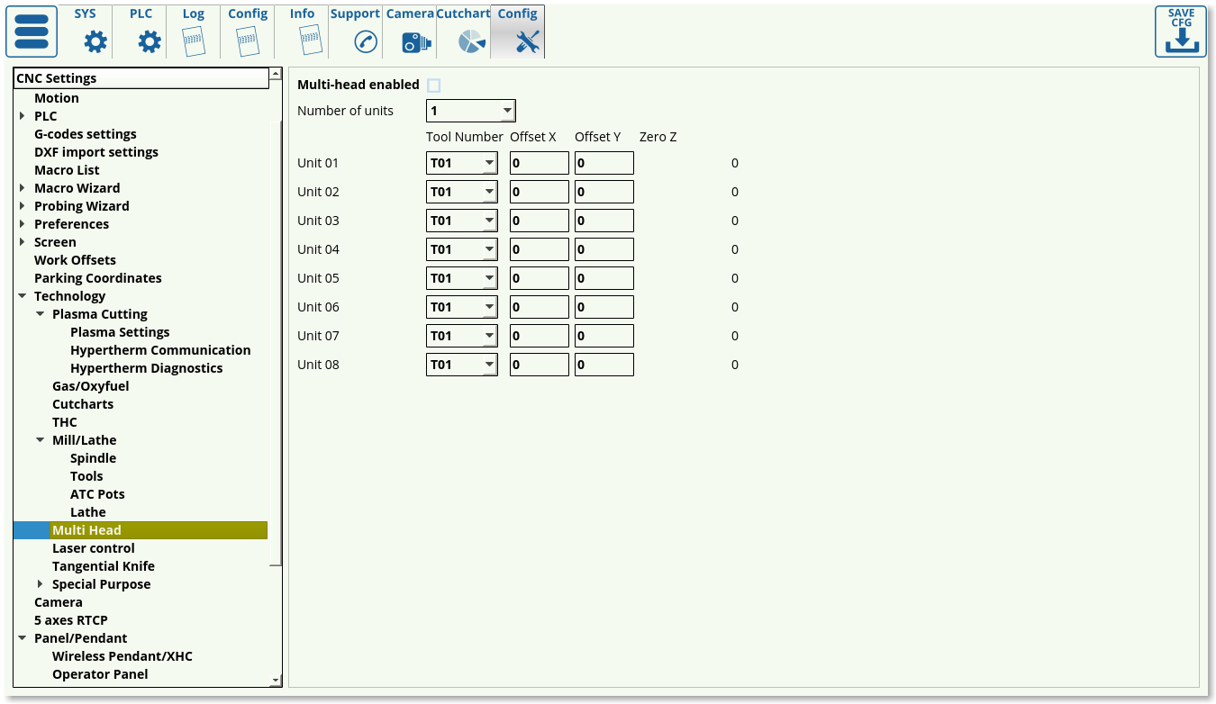
Multi Head
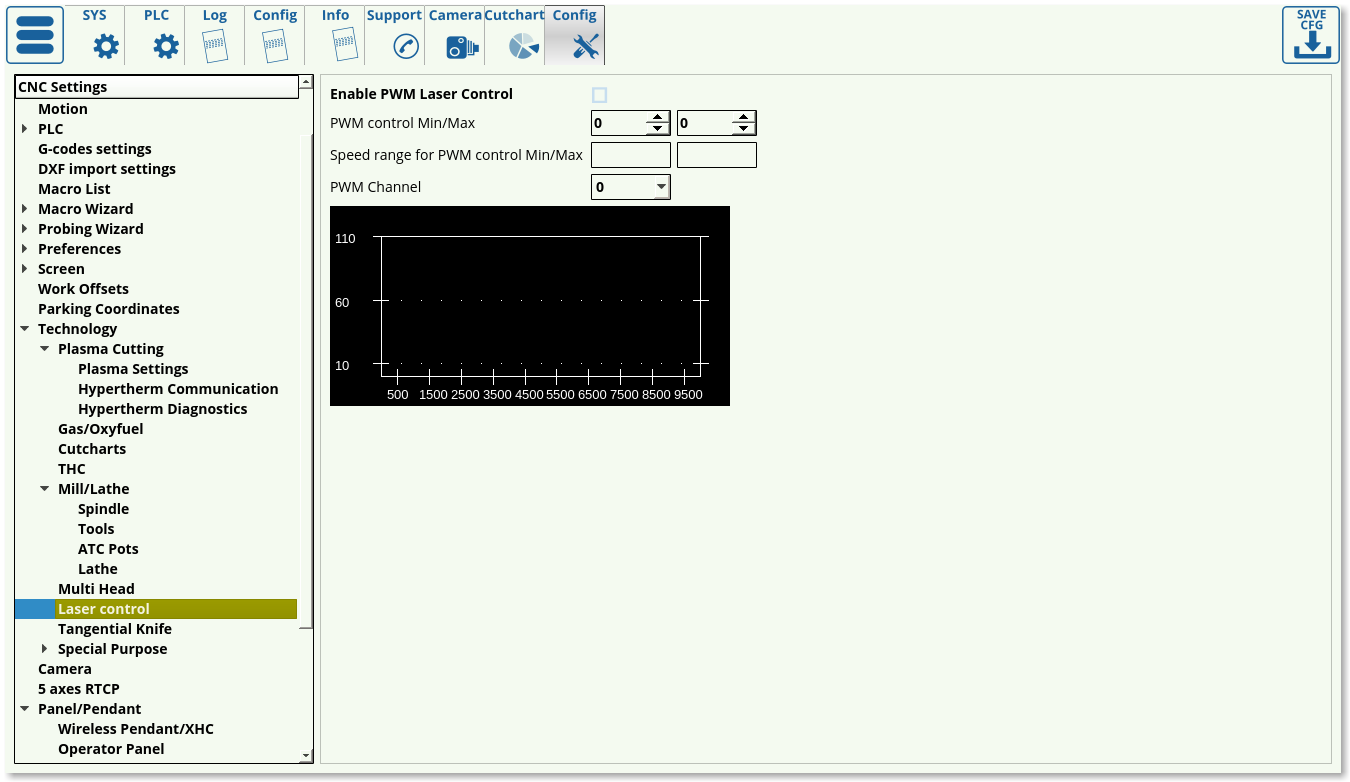
Laser Control
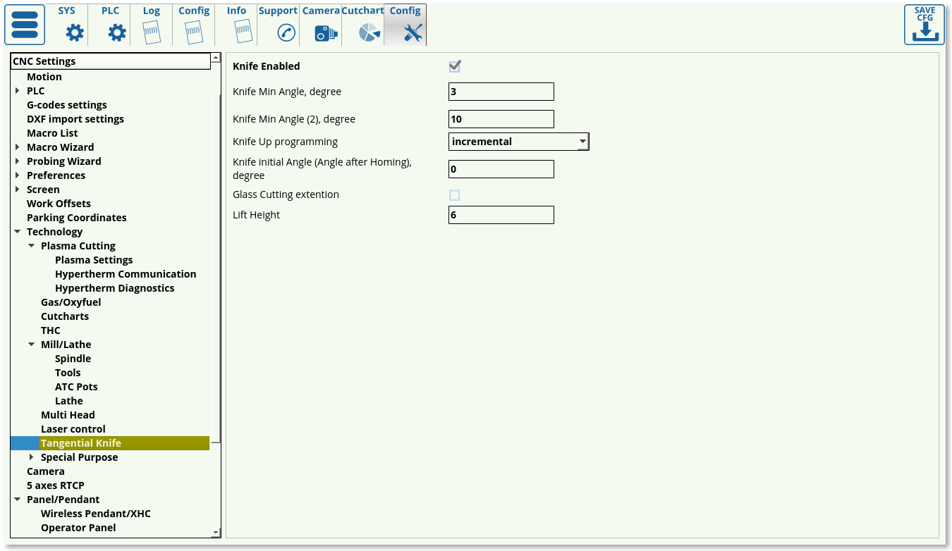
Tangential Knife
Special Purpose
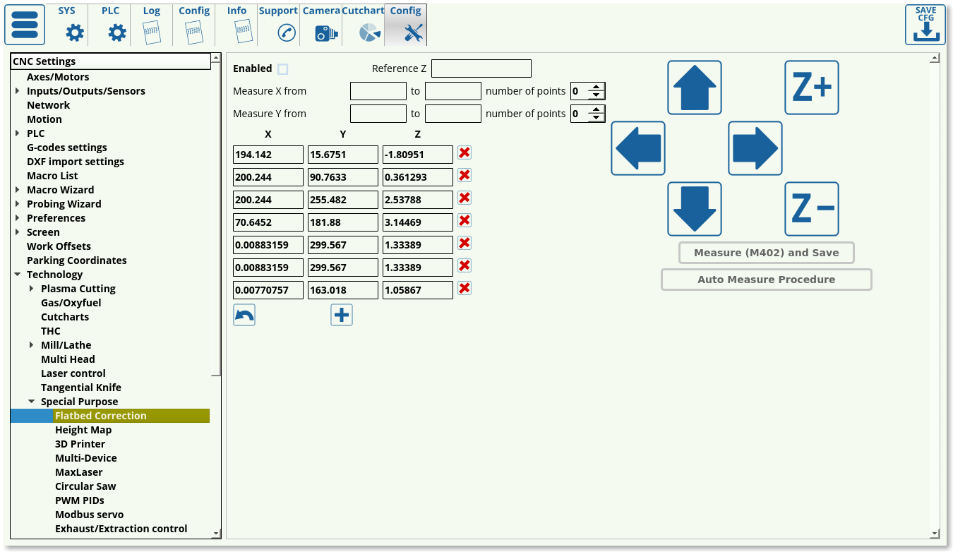
Flatbed correction
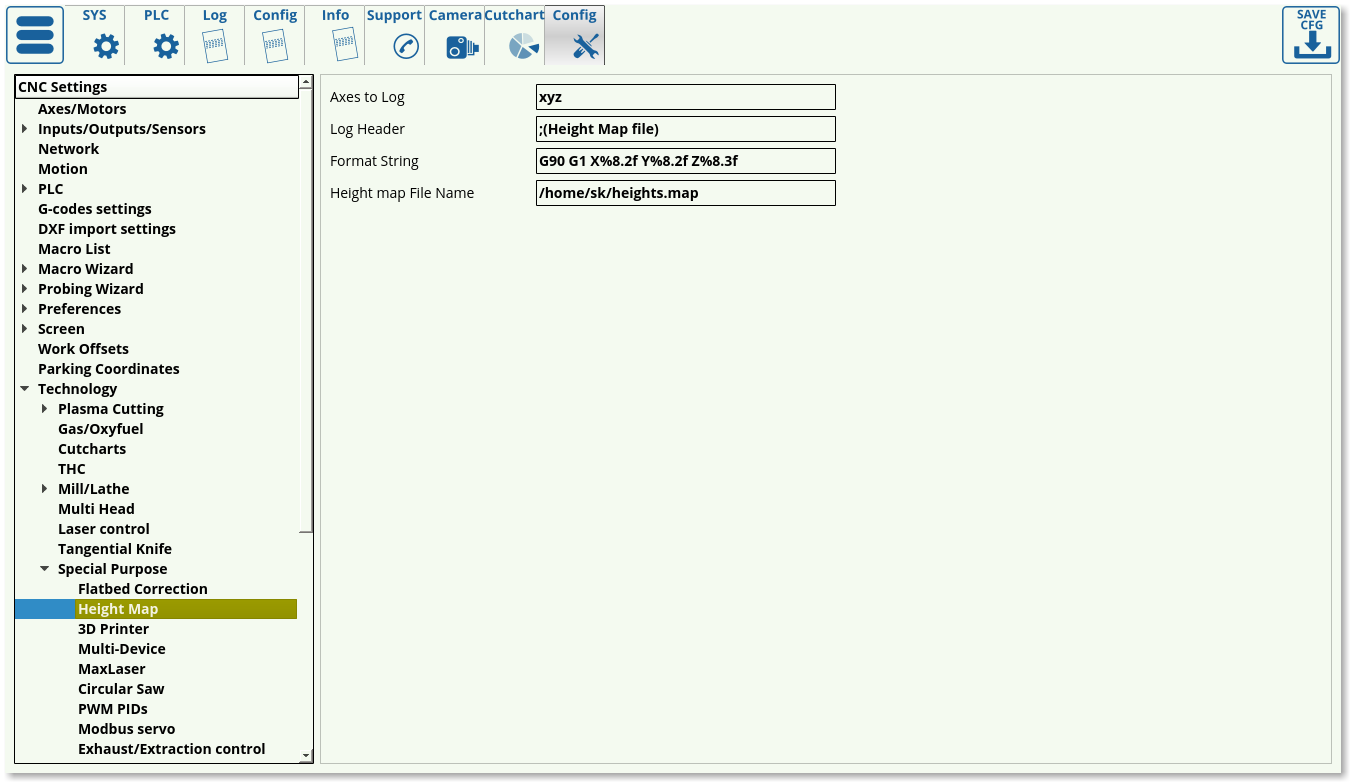
Height map
3D Printer
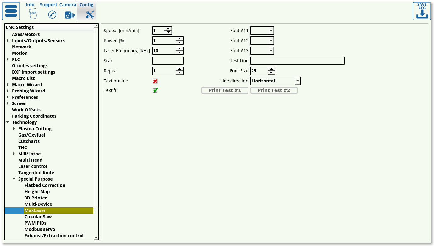
MaxLaser
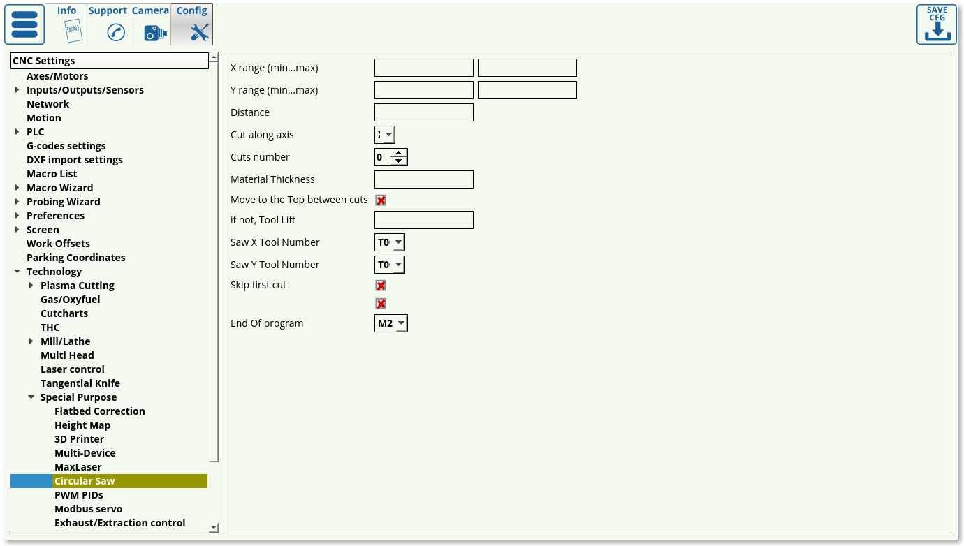
Circular Saw
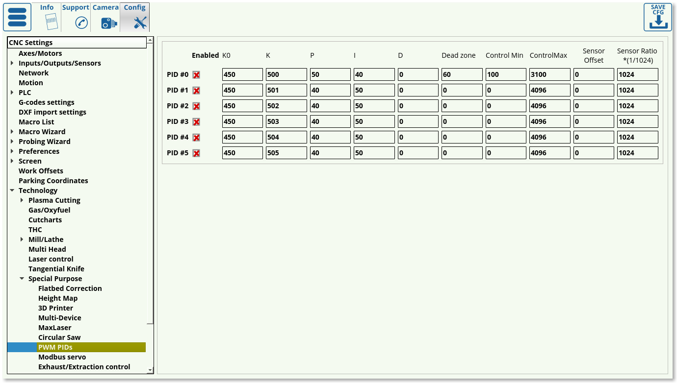
PWM PIDs
Modbus servo
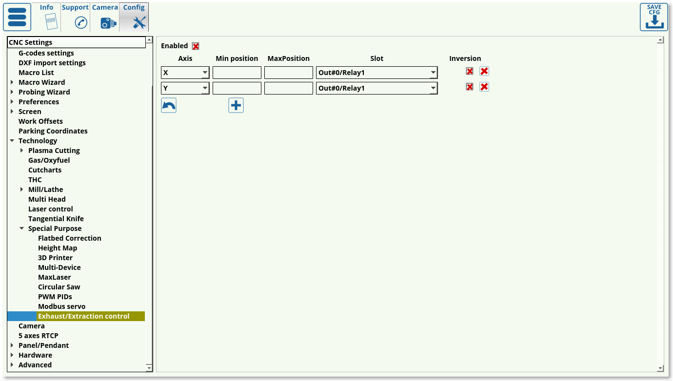
Exhaust/Extraction control
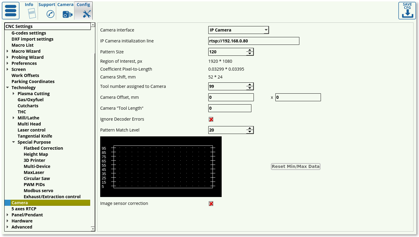
Camera
For a full overview of CNC Vision Camera setup, please consult the QuickStart CNC Vision manual.

