This is an old revision of the document!
Table of Contents
myCNC-ET6 CNC controller
ET6 Top View

Power supply connection
24V DC is used to supply myCNC-ET control board. Power consumption depends on external peripherals you have connected to open collector outputs and +12V/+5V outputs. Normally power supply 24V/2A should be enough to power up the controlller based kit with single board computer and 15'6“ TFT screen. However, step-down converters on the ET6 board have start current about 1.5A and 24V/1A power supply might be not enough to supply the single ET6 board.

Pulse-Dir outputs
ET6 has 6 channel pulse/dir outputs, 3MHz max pulses frequency.
ET6 pulse dir outputs conforms RS422 standard and compatible with most of servo and stepper drivers (line driver with paraphase signals positive and negative polarity). Internal schematic for pulse-dir is shown on a picture below.
Pulse-dir schematic

Pulse-Dir connectors pinout shown below


ET6 Output pins
ET6 board contains 7 output pins-
- 2 relay outputs (OUT#0, OUT#1)
- 2 open collector outputs (OUT#2, OUT#3)
- 3 PWM outputs (PWM#1, PWM#2, PWM#3)
WARNING: ET6 board rev.1 has Output pin names printed on Botton side of the board.
This names are NOT correct and differs from actual output addresses.
Please check table below to find out actual output address
| SILK print | Actual Output Pin Address |
|---|---|
| OUT0 | OUT2 |
| OUT1 | OUT3 |
| OUT2 | PWM1 |
| OUT3 | PWM2 |
| OUT4 | PWM3 |
| P2A | OUT0 (A) |
| P2B | OUT0 (B) |
| P2C | OUT0 (C) |
| P1A | OUT1 (A) |
| P1B | OUT1 (B) |
| P1C | OUT1 (C) |
Schematic for ET6 outputs is shown below

Connector pinouts for ET6 outputs pin shown on a picture below

Galvanic isolated inputs
ET6 control board has 8 galvanic isolated binary inputs, 2 groups of 4 inputs each. Each group has separate power supply pins so inputs can be powered from different power sources. Using PNP and NPN sensors simultaneously if possible too.
Schematic for ET6 inputs is shown below

Connector pinouts for ET6 galvanic isolated inputs shown on a picture below

RS422/RS485 Bus
myCNC-ET6 control board has RS485 bus connector. Modbus ASCII/RTU and Hypertherm Serial communication interfaces are implemented in myCNC-ET6 control board.
RS485 bus schematic is shown below

RS485 connector pinout shown below

DAC output
myCNC-ET6 control board has DAC output for spindle speed control. DAC output range is 1..15V Actual Max DAC voltage (ie 10V, 5V, 6V) can be setup in the myCNC control software.
Schematic design of DAC output is schwn below

Connector pinout for DAC output

Connection Examples
3-wire NPN sensor connection example

3-wire PNP sensor connection example

Spindle speed control through DAC (0-10V)

ET6 control board firmware reflash

myCNC-ET6 reflashing procedure may take about 3 minutes.
To reflash the board
- Plug 24V DC supply
- Plugin micro-USB cable to ET6 & Host Computer with myCNC software installed
- Close (short) jumpers J5(reset) & J6(programming) on myCNC control board
- Open (remove) J5 jumper.
- Open myCNC software on the Host computer,
- goto Configuration Tab → Support Tab
- Set “Select board” set to “myCNC-ET6”
- Select “Firmware version” from “Release”, “Night build” or “Testing”
- Set *UART port* to port with FT232 attached
- Set *Baud Rate* set to “115200” for ET6; other baud rate can be selected in case of problems on 115200 speed
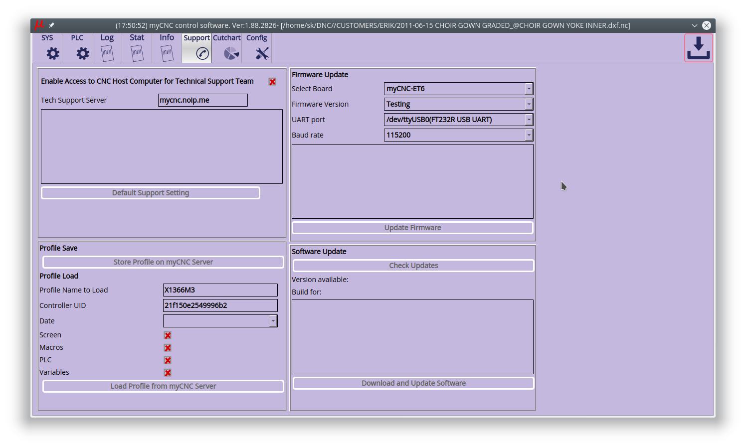
- Press “Update Firmware” button, Firmware download and reflashing process will be started.

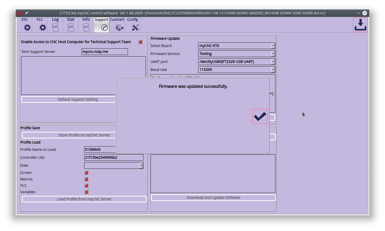
- Sector 0 will be written at the end of process. After firmware process finished, a popup message will be shown.
- Remove all jumpers (J5, J5) and restart the board. To restart the board you need
either repower ET6 or
close Reset jumper (J5) for 1 second, then release it. The board will be restarted.


In case reflashing process failed, you get a popup message.  Please repeat procedure from #3
