This is an old revision of the document!
Table of Contents
Rotary encoder connection and setup
There are 2 types or rotary encoders widely used in Pendants and operator panels -
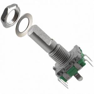
- Simple rotary encoder based on 2 switches. This type of encoders usually generate 10-40 pulses per revolution (PPR) and used as fancy style “endless multi-turn potentiometer”.
Both types can be connected to myCNC controller and used in operator control panel.
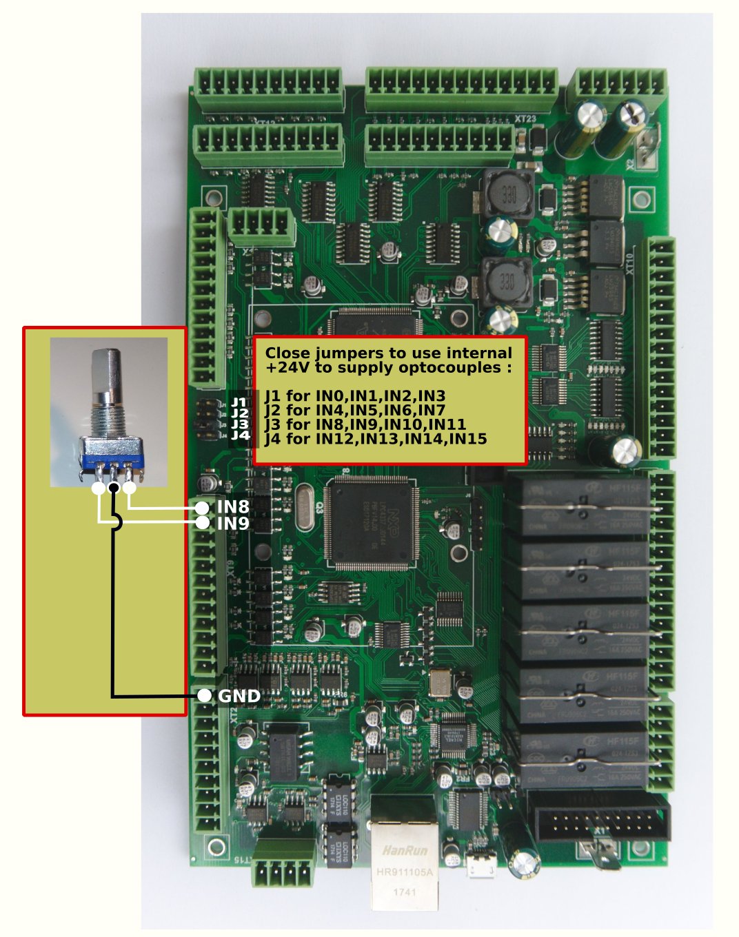
EN11 rotary encoder connection
Encoders can be connected to galvanic isolated binary inputs. 2 Inputs are used to connect each encoder.
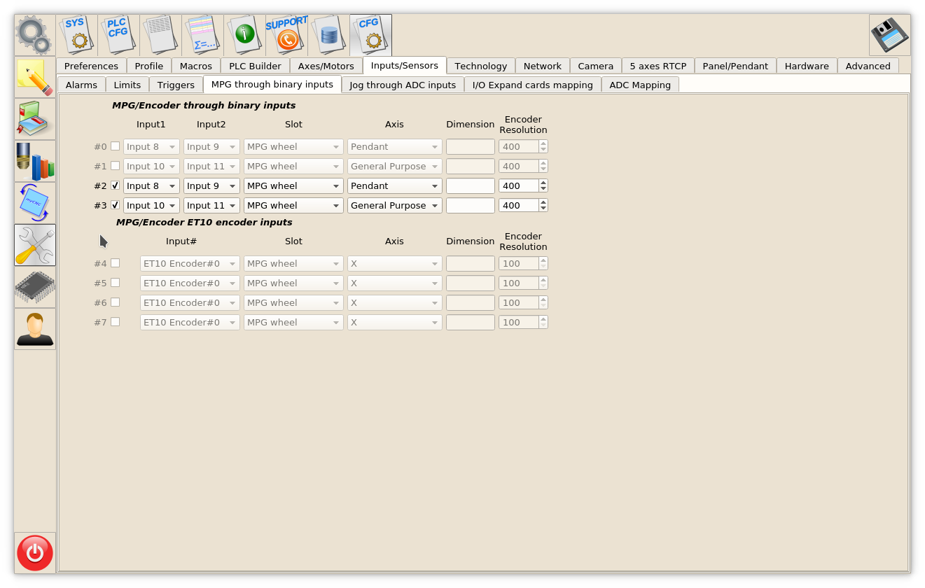
Encoder should be setup in Cfg→Inputs/Sensors→MPG through binary inputs configuration dialog.
myCNC controllers support up to 4 software encoders defined through binary inputs.
ET7 controller slow encoders setup
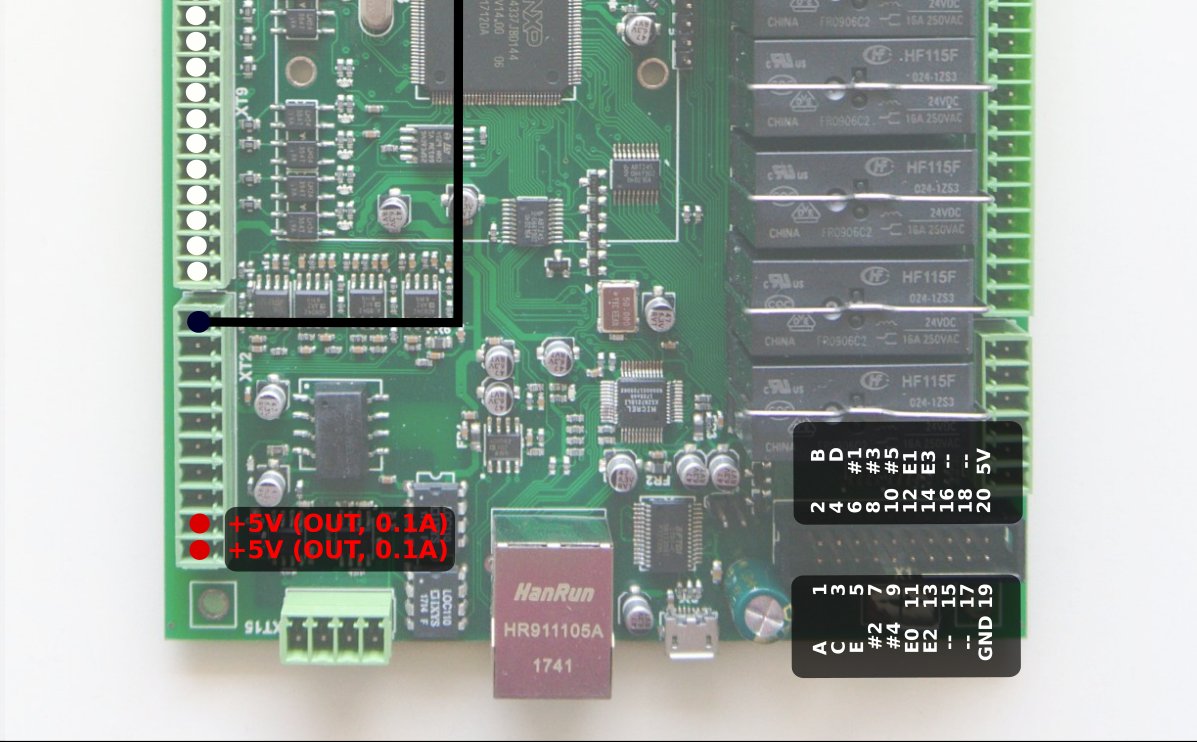
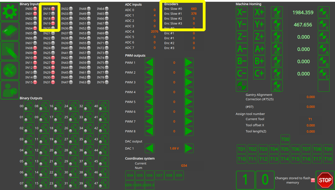
However myCNC-ET7 control board has 2 encoders (Encoder #0, #1) defined permanently. These encoders are supposed to be installed on ET7-Key keyboard panel and connected to the 20-pin X4 connector on ET7 control board. It's possible to use external encoders without ET7-key panel board and connect it directly to X4 pins 11,12,13,14 and 19. See the table below.
ET7 connector X4 pinout table
| X4 connector to External 25-keys keyboard | ||
|---|---|---|
| Pin# | Name | Comments |
| 11 | E#0 | Binary input #16, En#0 A |
| 12 | E#1 | Binary input #17, En#0 B |
| 13 | E#2 | Binary input #18, En#1 A |
| 14 | E#3 | Binary input #19, En#1 B |
| 19 | GND |
These pins are actually Binary inputs #16, #17, #18, #19 which are permanently configured as Encoder#0 and Encoder#1 in myCNC-ET7 controller firmware. This is the reason Slow Encoders #0, #1 configuration for ET7 controller in myCNC software is ignored and can be skipped. However, Encoder #2, Encoder#3 can be attached to any or binary inputs and configured accordingly.
For all other control boards ET6, ET10, ET15 all slow encoders configuration #0 - #3 is active and can be used by users.
Rotary encoders setup example is shown on a picture below
There are 2 encoders attached on Inputs #8,9,10,11 and set up in the dialog.
- Encoder #2 is attached to inputs #8 and #9 and used as a Pendant MPG/Wheel.
- Encoder #3 is attached to inputs #10 and #11 and used as a general purpose encoder.
For ET7 controller Encoders #0, #1 connected to X4 connector pins 11-14 (or through ET7-KEY keyboard) are configured despite on disabled settings.
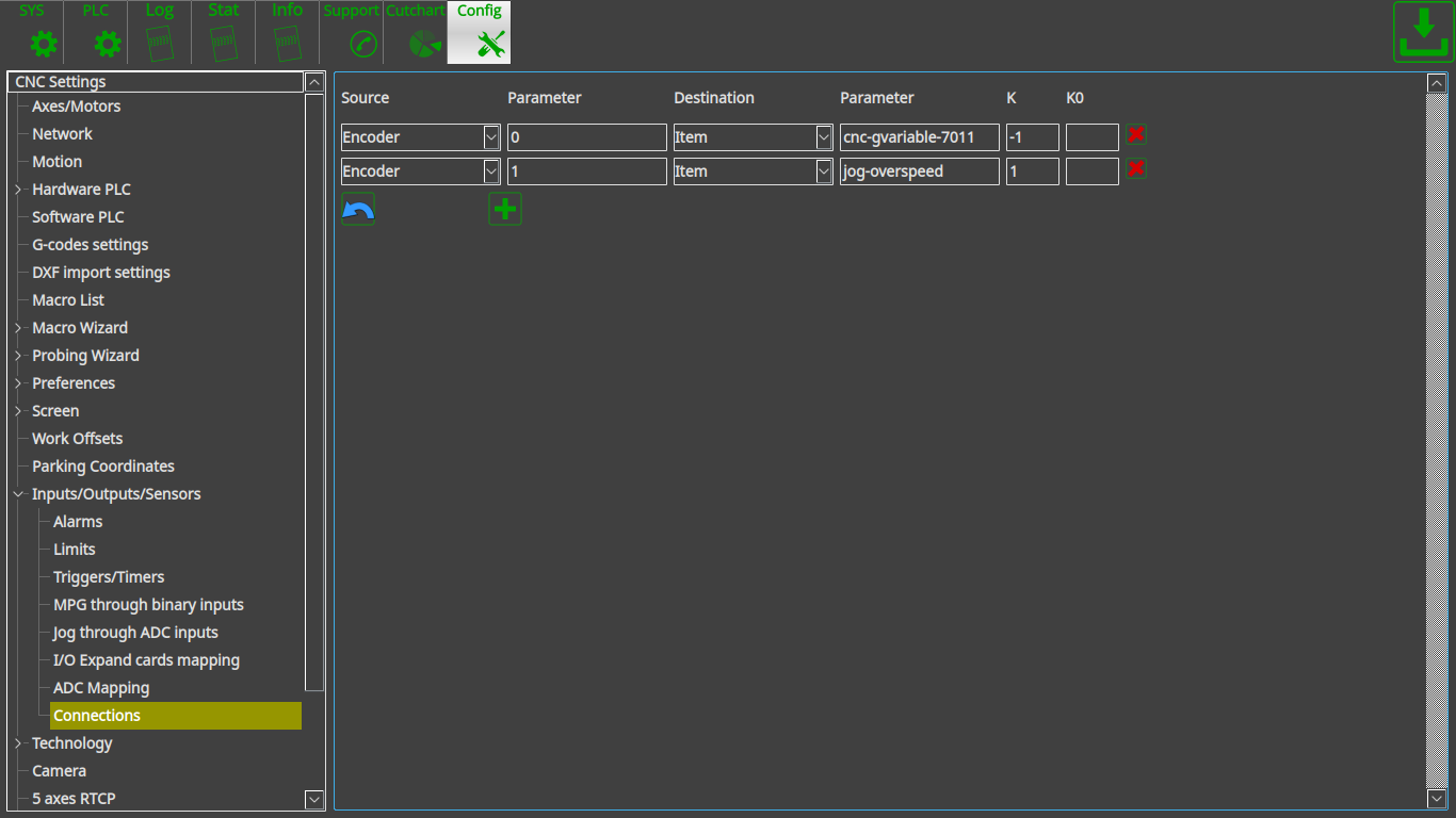
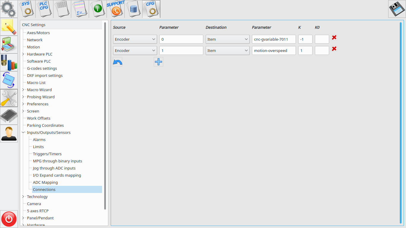
Encoder connection setup through configuration dialog.
A general purpose encoder can be connected to one of the system variables for convenient control.
There is configuration dialog to set up connection between slow encoder values and CNC parameters.
- Source - source of connection - can be Encoder, ADC, input/output pin, PWM, global variable or other parameters
- Source/Parameter - address of source. It can be Encoder number, input pin number, global variable address etc
- Destination - destination connection
- Destination/Parameter - destination address
- K - destination ratio. For example, Spindle speed will be increased 100RPM every encoder click if “K=100”.
On-panel rotary encoders mostly used to control on-the-fly
- Overspeed [%]
- THC Arc reference voltage [V] (actually cutting height)
- Spindle speed
A rotary encoder should be connected to XML configuration Item “motion-overspeed” to control Overspeed [%]
Global variable register 7011 is used to change on-the-fly Cutting height (THC Arc reference voltage)
To change Spindle speed XML Item “spindle-default-speed” can be used.
| Name | Destination type | Parameter |
|---|---|---|
| Overspeed [%] | Item | motion-overspeed |
| THC Arc voltage reference | Item | cnc-gvariable-7011 |
| Spindle Speed | Item | spindle-default-speed |
Obsolete method to establish connection through "cnc-variables.xml" configuration file.
(this method was used before the dialog described above was issued)
The connection assignment can be written directly in cnc-variables.xml configuration file . For example
<value name="cnc-connection-item-002"
source="encoder:3"
dest="item:motion-overspeed" >0</value>
- source=“encoder:3” - encoder #3 defined as a source
- dest=“item:motion-overspeed” - motion-overspeed defined as destination
Encoder #3 connected to motion-overspeed variable. Overspeed (%) value will be changed by rotating the encoder.
<value name="cnc-connection-item-003"
source="encoder:2"
dest="item:cnc-gvariable-7012">0</value>
- source=“encoder:2” - encoder #2 defined as a source
- dest=“item:cnc-gvariable-7012” - Global variable for THC Arc Voltage Adjustment value is a destination for the connection
Encoder #2 connected to THC Arc voltage adjustment. Adjustment Arc value will be changed “+1” or “-1” every encoder click.

