Table of Contents
MyCNC closed loop configuration
A proportional–integral–derivative controller (PID controller) is a control loop feedback mechanism widely used in industrial control systems and a variety of other applications requiring continuously modulated control. A PID controller continuously calculates an error value E(t) as the difference between the desired setpoint position (POS) and a real position measured by encoders (ENC) and applies a correction based on proportional, integral, and derivative terms (denoted P, I, and D respectively).
PID controller formula implemented in myCNC is

where
- Kp is the proportional gain, a tuning parameter,
- Ki is the integral gain, a tuning parameter,
- Kd is the derivative gain, a tuning parameter,
- E(t) = (POS − ENC) is the position error (difference between a job position real position measured by encoder),
- t is the time (the present).
Digital-Analogue Converter (DAC) output voltage is the sum of the PID and a DAC offset volage

Enable/Disable PID control does not affect the DAC voltage offset.
If PID control is disabled for selected channel, output voltage is equal to DAC Offset
U_out = U_offset
PID controllers setup
To setup Closed-loop analogue PID
- Goto “Encoders” configuration widget. Setup Encoder resolution for each channel you going to use
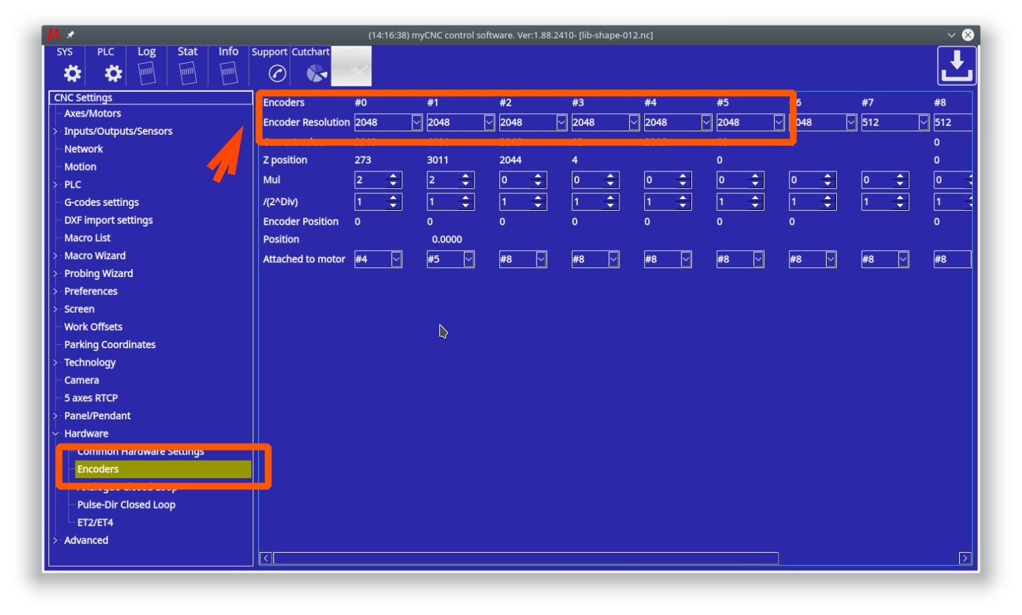
- Set Multiplication ratio to “2” and divider (/2^Div) ratio to “1” to get result ratio
2/(2^1)=1
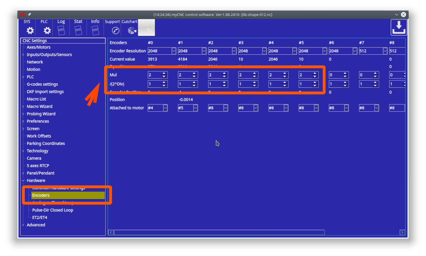


Multiplicator and divider ratio needed for pulse-dir closed loop system
to adjust encoder resolution (encoder lines-per-rotation) to motor driver
pulse-dir resolution.
For Analogue closed loop system this ratio should be "1"
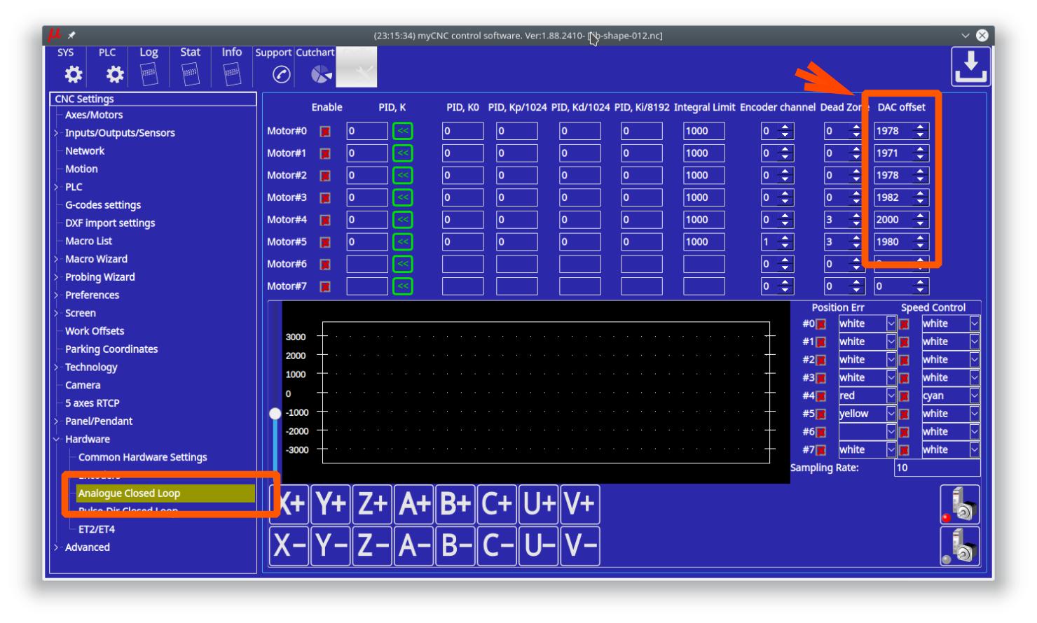
- Adjust DAC offset ratio to get “0V” value on DAC output for each channel. Theoretical DAC value for 0V is the middle of 12bits range
4096/2=2048.
A real value may vary +/-5%.
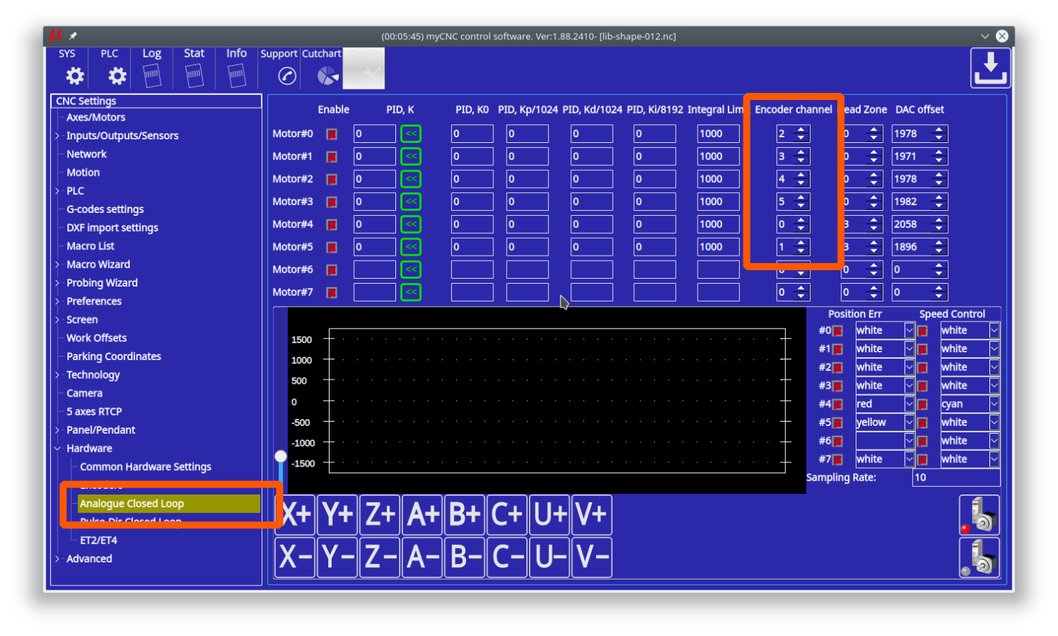
- Fill Encoder channel for each PID (Motor#).
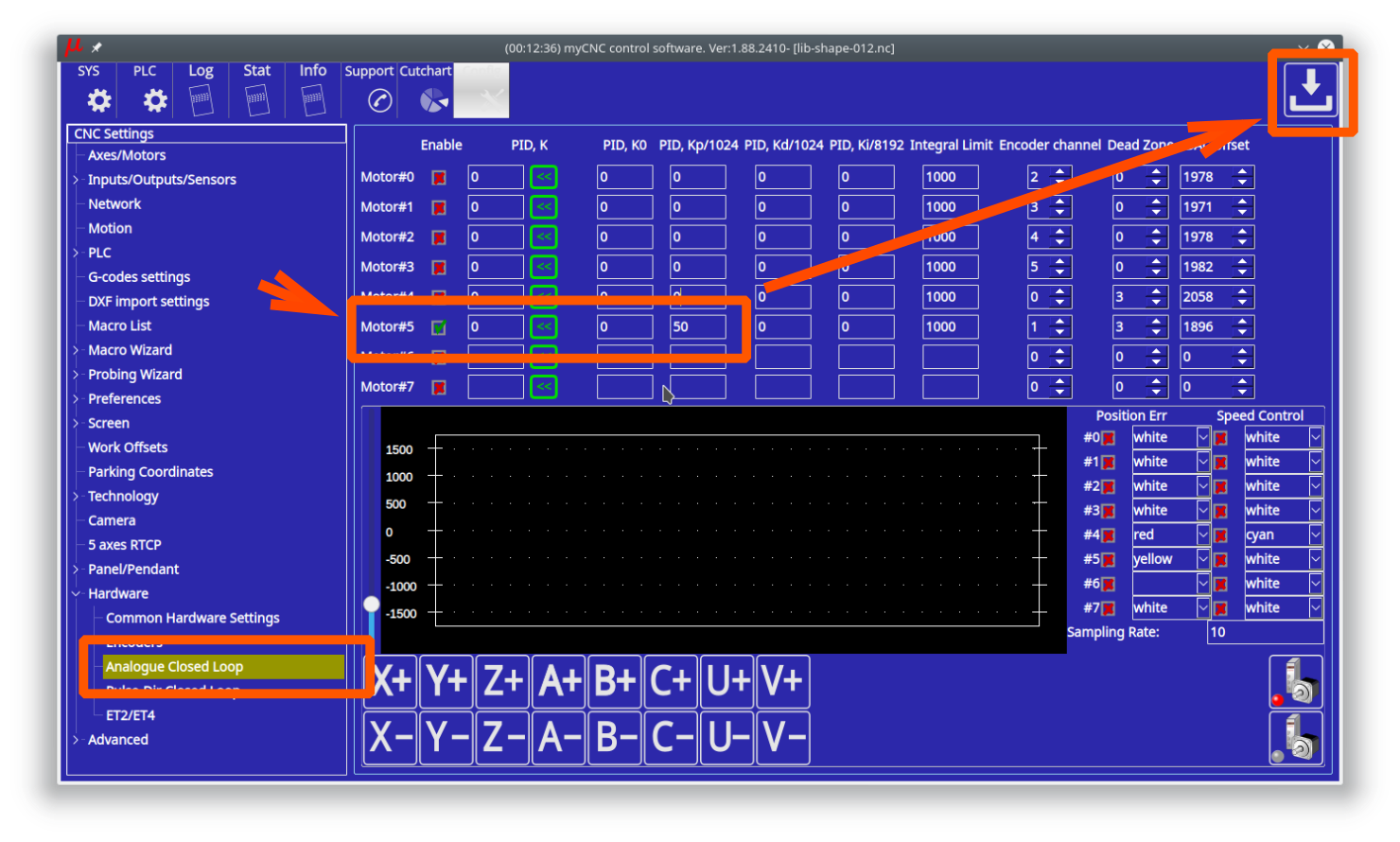
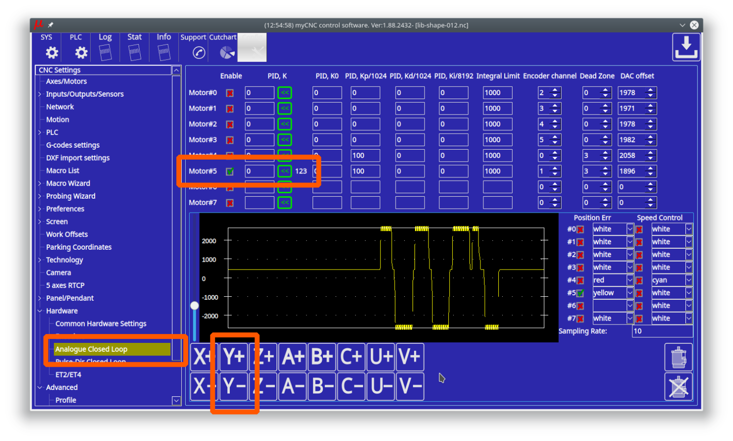
- To test selected channel, check “Enable” checkbox for the channel and enter initial value of “50” for Proportional P-ratio of PID controller. Press “Save” button to save the changes. We test PID#5 (motor channel #5) on the screenshot below.
- Click on “Servo-ON” button to reset & enable selected PID and turn ON “Servo-ON” signal. Servo-On procedure will …
- Reset position error registers - E(t) and its Integral value.
- Turn ON Servo-ON output to enable a servo driver
- Turn ON all “Enabled” PID controllers (Checkboxes “Enable” are checked).
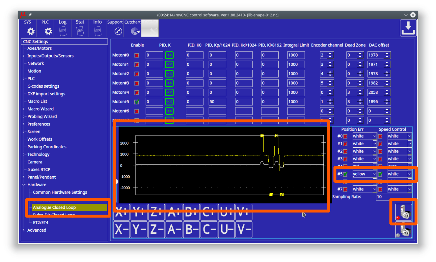
- Select the channel for a scope widget to control and tune PID controller ratios.
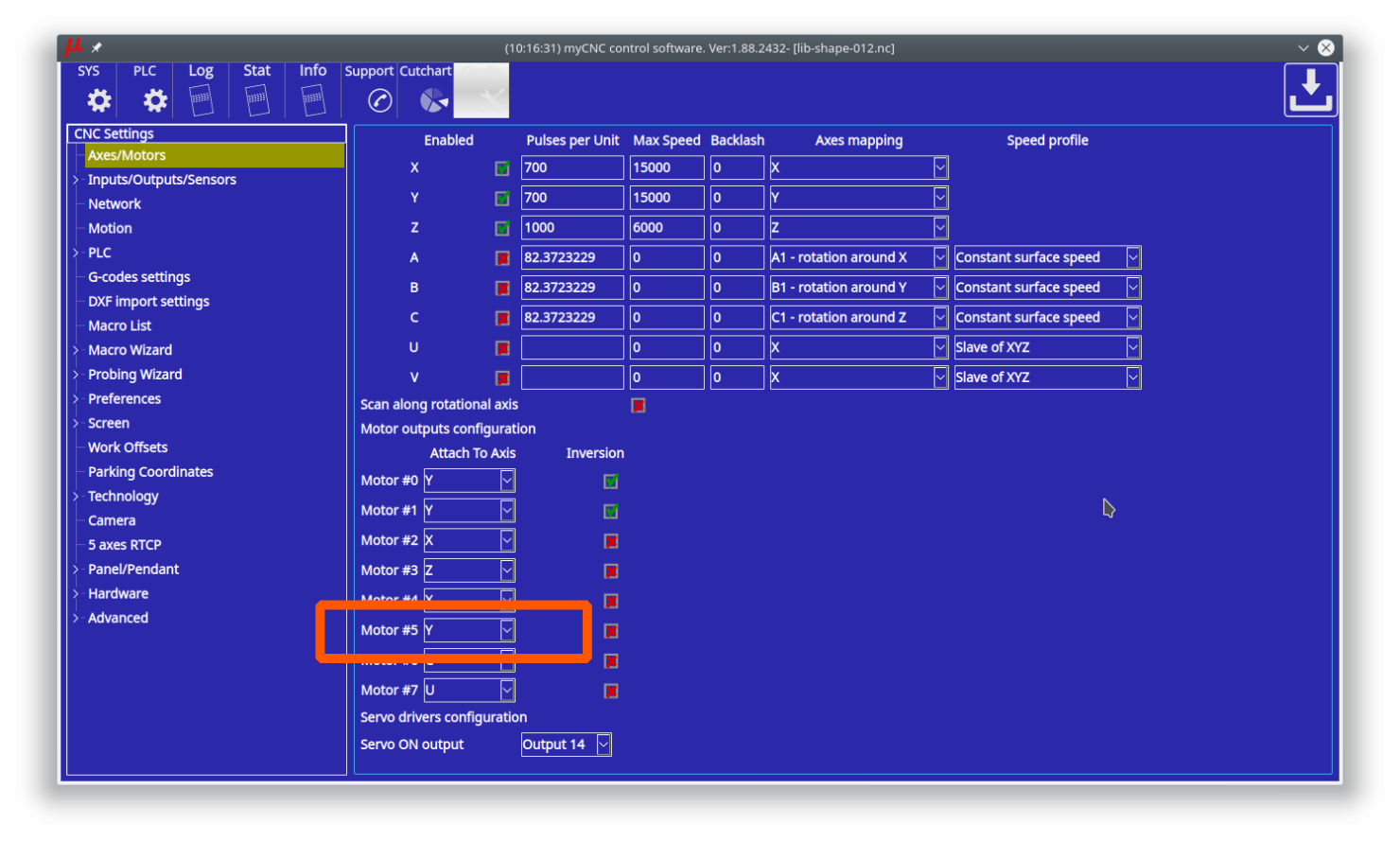
- Check which Axis the PID controller attached to (Y axis for the screenshot below).
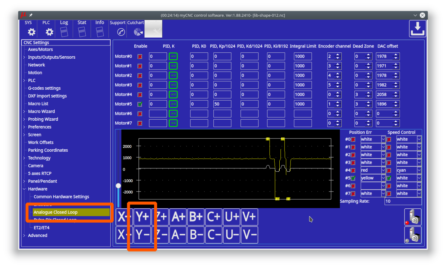
- Jog buttons can be used to move the axis while testing and tuning the PID coefficients.
- An analogue servo driver normally has a linear function of rotation speed depends on input voltage. A linear coefficient of this function depends on Servo driver and motor, gears, ball-screw etc.
PID K value represent this coefficient.
The value can be tuned manually. If rotate a motor shaft with speed more than 20 turns/sec, the controller calculates real Speed/Voltage coefficient and print it on the configuration widget. You can use this value as information to tune the PID K ratio. A button « to the right of PID K input line can be used to copy the measured K ratio to PID K.


Servo ON handling
Depends on machine configuration you may want
- On-Screen buttons to turn ON/OFF your Servo drivers
- Automatic turn ON Servo Drivers when CNC control loaded and ready to go
Both options can be implemented with myCNC control software.
There are few ways to Enable/Disable Servo PID loops in myCNC software
1. On-Screen button. To enable/disable Servo PID control button should have actions:
action="servo-pid-on"  (enable pid)
action="servo-pid-off"  (disable pid)
For example
Buttons for Servo-ON and Servo-OFF
<gitem where="toolbar-servo" image="motor/motor-start" action="servo-pid-on"
height="80" event="pressed-delay-1000" type="button"/>
<gitem where="toolbar-servo" image="motor/motor-stop" action="servo-pid-off"
height="80" type="button"/>
Popup widget container for Servo Pid On/Off buttons
<quick-popup-layout>
<current>popup-servo</current>
<layout stretch="0" name="popup-servo" wa="80;160;right" orientation="vertical" skin="skin/metal-01">
    <widget stretch="1" spacing="0" name="toolbar-servo" orientation="vertical">myitems</widget>
</layout>
</quick-popup-layout>
Button to show containner with 2 buttons for servo-on/servo-off buttons and led to show current servo pid state
<gitem where="magic" position="960;0" width="80" height="80" image="motor/servo-driver"
action="mypopup-toggle:popup-servo" xattr="56;4;20;20;led;green;round"
address="outputs" number="47" type="xbutton" />
2. Using Global Variables API. Global variables 60000 and 60001 are mapped to turning On and Off Servo PID control.
- Write “1” to register number 60000 will turn ON Motor closed-loop control PIDs
- Write “1” to register number 60001 will turn OFF Motor closed-loop control PIDs
Reading this registers has no effect and return zero value. Read more about Servo ON/Servo OFF commands in this short manual: Servo ON/OFF.
3. Automatic Servo ON/OFF. There are 2 handler procedures in Software PLC can be used to automatic PID ON/OFF.
- _HANDLER_INIT - procedure executed once just after CNC control software loaded, connection with myCNC controller established and a complete configuration is sent to the controller.
- _HANDLER_EXIT - procedure executed while myCNC control software shut down the process.
To handle automatic Servo ON/OFF writing to registers 60000, 60001 should be added to handler procedures. Example is below
- __HANDLER_INIT.PLC
main()
 {
  gvarset(60000,1);  //turn Servo PIDs On
  exit(99);
 };
- __HANDLER_EXIT.PLC
main()
 {
  gvarset(60001,1);  //turn Servo PIDs Off
  exit(99);
 };
Analogue -10V/+10V outputs Test Mode
To test DAC outputs voltage range, rising/falling edges timings DAC Test mode is used. DAC Test mode is activated if in Hardware→Encoders configuration dialog, /(2^Div) line for Encoder#11 column set “99” value and press “Save” button.

In DAC Test mode all DAC outputs generate Zero » MAX » Zero » MIN sequence with frequency about 700Hz. Scope screen example is shown below.

Value "99" should be used for DAC test mode ONLY!
For working mode any other value from "1" to "90" should be used in "/(2^Div)" line for "Encoder#11".
Analogue -10V..+10V/Incremental encoder closed-loop setup
- Goto Encoders settings tab.
- Setup Encoder resolution for All Encoders used.
- Set Multiplication ratio Mul to “2” for all the Encoders.
- Set Divider /(2^Div) to “1” for all the Encoders. Result Ratio willl be 2/(2^1)=1
- Setup Attached to motor for all Encoders used.
Pulse-Dir/Incremental Encoder closed-loop setup
Example: Let's use Motor output #2 (configured as axis X) and Encoder #1 to build closed-loop PID control.
- Goto Encoders settings tab. If rotary encoder is used as a feedback - setup Encoder resolution for Encoder #1. For linear encoder set resolution 2500.
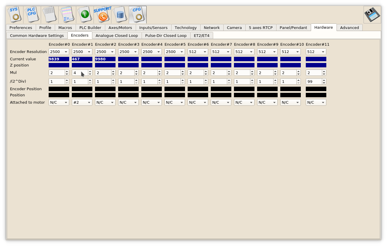
- Set Mul and /(2^Div) ratios to get result Encoder resolution equal to Pulses-per-Unit resolution. For example
Servo driver with 2500 pulses per revolution,
Electronic gears "1" and ball screw 5mm are used.
Linear encoder with 1um resolution used as a feedback.
=>((A)) Pulses per unit value is (2500*4)/5=2000 pulses per mm
Original Linear encoder resolution (1um) is 1000 pulses per mm, need to set
multiplier to "4" and divider to "1" to get result ratio
4/(2^1)=4/2=2 and
=> result Encoder resolution is 1000* 4/(2^1)=2000 pulses per mm (which is equal to ((A))
- Set Attached to motor to “#2”
- Goto Pulse-Dir Closed Loop ang setup PID parameters for PID attached to Motor#2.
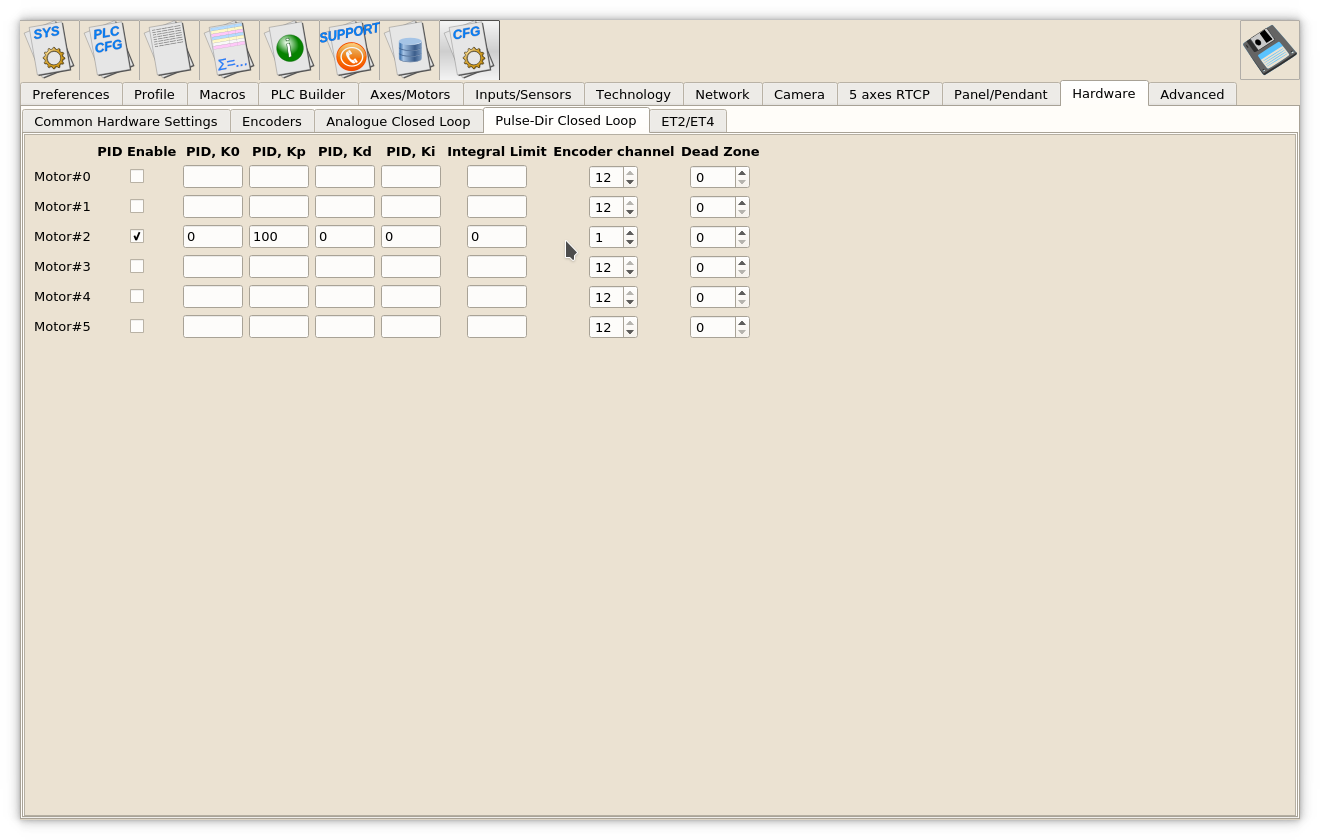 The most important parameters are
 - PID proportional ratio Kp
- PID integral ratio Ki
- PID integral limit. An integral value will be limited by given value.
- Encoder channel used as PID feedback

