Table of Contents
Gantry Alignment
Gantry Alignment macro wizard helps the user to generate a program macro for dual motor gantry alignment. There exist several possible methods for gantry alignment. Almost any method can be implemented by the (skilled) user through the macro/PLC layer, and the Macro Wizard is used to facilitate this process by quickly generating the gantry macro after the user inputs their preferred settings into the wizard. In this manual, we will show two common methods which are often used for gantry alignment.
The following video goes over this manual:
Please consult the manual below for all referenced PLC/macro code.
Method 1
Two sensors on each side of the gantry are used to find the side position. The alignment procedure is as follows:
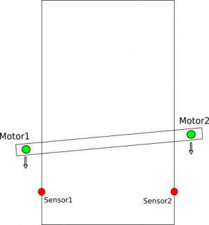
- CNC activates motors on both sides and moves towards the sensors.
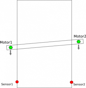
- When one of the sensors is triggered, CNC control disconnects the motor on that side, while the second motor continues to move.


- When both sensors are triggered, the motion stops.
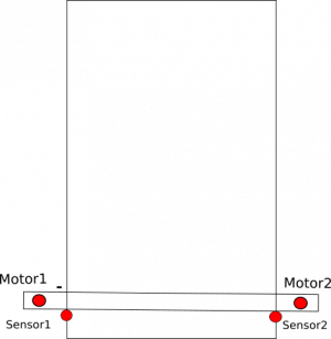
- It is important to note that the sensors do not have to be perfectly aligned on the same line - they can be placed wherever it is convenient, provided that the offset distance between them is accounted for in the Tuning field:


- Both motors are activated and move together.
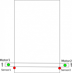
- The machine moves out from the sensors by a predefined distance:


To generate this kind of alignment, the alignment macro will be generated by the Macro Wizard. A screenshot of the Macro Wizard screen is shown below:

On this screen, we have:
- Axis, Direction - In this example, the macro will be generated for the y-axis
- While alignment machine moves toward Y-MIN
- Sensor numbers - sensor #0, #1 are used as sensors on each side of gantry, both senors are “Normally Closed”
- Use Encoder Z signals for align - not used
- Ignore Limits while align - If sensors #0 or #1 is used as limit sensor, then Limits should be ignored (set the check mark to ON) during the alignment procedure to prevent the machine from aborting the procedure once the limit sensors are triggered.
- Align while move - set to Forward in this example.
- The Forward configuration works as follows: One side reaches the sensor, and the motor for that side stops, while the other side's motor continues forward until the opposite sensor is reached, then stops as well. This method is not ideal as the first initial stop is done at a high speed as the machine suddenly comes into contact with the sensor. The other method is to go Backwards, by triggering one sensor, passing that sensor on one side, then reaching the sensor on the other, and afterwards aligning the system by using the first initial sensor. This method is preferable as the alignment process is done at a lower speed, however it is not feasible if the sensors are set up right near the edge of the table, preventing the machine from moving past them (in that case, the Forward setting should be used).
- Final tuning (Motor #1 offset) - set distance to adjust sensors
- Double check - allows for greater precision when using the Forward movement method. This is done by moving back after hitting both sensors and then forward again at a slower speed.
- Move distance Distance expected from start position to alignment sensors. This distance should be set a more than real distance to alignment sensors.
- Gap - move out from the sensors for a given distance.
- Speed - speed for the motion toward the sensors
- Slow Speed - not used for “Align while move:Forward” method (this would be the speed on the backwards movement).
- Reset work position after align allows the work position to be set to the alignment position after the procedure has been completed.
- Macro filename - File name to save the macro source to file.
To generate and save macro (As usual for the Macro wizard) 3 buttons should be pressed
- Save (top-right corner - to save macro wizard settings and use them for future macro generation)
- Generate - to generate macro source and show it in “Macro preview” window. If the Generate button is pressed, the new macro is shown ONLY in the preview window and is not activated !! At this point, the user can manually edit the macro source in Macro preview window
- Save Macro - save macro from the Macro preview for the macro file with the name given in Macro filename, then reload all macros to CNC memory.
Gantry Alignment procedure either can work simultaneously as a homing procedure (if the alignment sensor is used as a homing sensor as well), or, alternatively, the Homing procedure can be run just after gantry alignment procedure has taken place.
Method 2
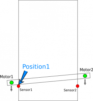
2 sensors on each side of gantry can used to find each respective side position. When both sensors' actual positions are found, CNC control moves only one side (using only one motor) to get the gantry aligned.
The alignment procedure is described below in further detail:
- CNC activates motors on both sides and moves toward the sensors.
- PLC controller procedure records machine positions at the moment that each respective sensor is triggered.
- Motion is stopped at the moment both sensors are triggered.
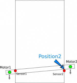
- PLC procedure calculates the difference between the recorded positions and adds an adjustment offset (if such an offset exists between the sensors)
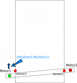
- The second motor control is then temporarily disabled, while the other motor moves the machine by the necessary distance to align the gantry
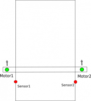
- Then, after the alignment has completed the second motor control is activated again and both motors will be moving together to move out by the set distance


Gantry alignment code walkthrough
For simply gantry alignments, it is largely unnecessary to edit the macro yourself, or to into much further detail beyound what's already shown in the manual above. However, if a complex gantry alignment procedure is necessary, or if you just want to understand what exactly is happening when gantry alignment is performed, here is a step-by-step description of the process:
- CNC activates the motors on both sides and moves toward the sensors.
NOTE: While both motors for the gantry alignment procedure should be already configured in the Axes/Motors tab in the myCNC Settings by default, additional M-code can also be used to make sure that both motors are turned on and ready to go before starting the procedure. This is done in situations where one of the motors might have been turned off previously due to triggering one of the sensors/limits, which would lead to issues when the gantry procedure would attempt to perform the alignment with only one motor being operational. For example, M219.plc connects axis X to motor outputs #0 and #1
- M219.plc
#include vars.h
main()
{

 parameter=0+16; //"0" is axis X; "16" is axis inversion.
 //parameter=1+16; //"1" is axis Y; "16" is axis inversion.
 //parameter=2+16; //"2" is axis Z; "16" is axis inversion.
 //parameter=3+16; //"3" is axis A; "16" is axis inversion.
 //parameter=4+16; //"4" is axis B; "16" is axis inversion.
 //parameter=5+16; //"5" is axis C; "16" is axis inversion.

 command=112+0; //Motor output #0
 message=PLCCMD_SET_CNC_VAR;
 timer=2;do{timer--;}while(timer>0);

 command=112+1; //Motor output #1
 parameter=0+16; //"0" is axis X; "16" is axis inversion.
 message=PLCCMD_SET_CNC_VAR;
 timer=2;do{timer--;}while(timer>0);

 exit(99);
};
- PLC controller procedure records the machine positions at the moment of each respective sensor being triggered. For this example, we use the M144 PLC procedure (written specially for this example). Any other implementation can be used as well
- M144.plc
#include pins.h

// Look after INPUT_GANTRY_S1 & INPUT_GANTRY_S2 input pins
// Position X is stored in register #801 when sensor s1 triggered
// Position X is stored in register #802 when sensor s2 triggered
// If both sensors triggered, then
//  - Motion will be stopped
//  - Position difference is calculated and stored the register #800

main()
{
 timer=0;

 message=PLCCMD_MOTION_CONTINUE;
 texit=timer+30;do{timer++;}while(timer<texit);

 mode_12=0;

 ready=0;

 s1_old=portget(INPUT_GANTRY_S1);
 s2_old=portget(INPUT_GANTRY_S2);

 do
 {
 timer++;

 s1=portget(INPUT_GANTRY_S1);
 s2=portget(INPUT_GANTRY_S2);

 mode1=mode_12&1;

 if (mode1==0)//if sensor 1 wasn't triggered
 {
  if (s1!=s1_old) //if the sensor is triggered now
   {
     mode_12=mode_12|1; //set flag for sensor1
     position1=gvarget(5021+0);	//Save Machine X position
   };
 };

 mode2=mode_12&2;

 if (mode2==0)//if sensor 2 wasn't triggered
 {
  if (s2!=s2_old) //if the sensor is triggered now
   {
     mode_12=mode_12|2; //set flag for sensor2
     position2=gvarget(5021+0);	//Save Machine X position
   };
 };

 }while(mode_12!=3);

 message=PLCCMD_MOTION_SKIP;
 timer=2;do{timer--;}while(timer>0);

 gvarset(801,position1); //send the position to myCNC software Register #801
 timer=50;do{timer--;}while(timer>0);
 gvarset(802,position2); //send the position to myCNC software Register #802
 timer=50;do{timer--;}while(timer>0);

 offset=position1-position2;
 gvarset(800,offset);
 timer=50;do{timer--;}while(timer>0);

 exit(99);
};
The M144.plc procedure uses predefined values as the input pin numbers that the alignment sensors are connected to.
#include pins.h
...
...

 s1_old=portget(INPUT_GANTRY_S1);
 s2_old=portget(INPUT_GANTRY_S2);


 do
 {
...
...

 s1=portget(INPUT_GANTRY_S1);
 s2=portget(INPUT_GANTRY_S2);

...
...
Actual input numbers should be defined in the “pins.h” file (Settings > Config > PLC > Hardware PLC > pins.h). The content of the “pins.h” file should be included at the start of each macro. If using this programming style, the “pins.h” is the single file you need to edit to customize your input/output assignments (as you will be referring to this file in all your other macros).
- pins.h
...
...
 #define INPUT_GANTRY_S1 3
 #define INPUT_GANTRY_S2 4
...
...
You can also put numbers directly into portget/portset functions of the PLC source to request the information directly from the specific ports themselves. However, we don't recommend this as it makes it harder to easily switch the inputs later - by using the pins.h file, the input list is centralized and easy to check. This method will look the following way:
...

 s1_old=portget(3);
 s2_old=portget(4);

 do
 {
...
 s1=portget(3);
 s2=portget(4);
...
- Motion is stoppped at the moment that both sensors are triggered. This is implemented in the M144.plc procedure.
The PLC sends message to the Motion controller to end the current motion and jump to the next line of the G-code.
 message=PLCCMD_MOTION_SKIP;
 timer=2;do{timer--;}while(timer>0);
- PLC procedure calculates the difference between the recorded positions and adds an adjustment offset (if one exists). This is implemented in the M144.plc procedure as well:
 gvarset(801,position1); //send the position #1 to myCNC software Register #801
 timer=50;do{timer--;}while(timer>0);
 gvarset(802,position2); //send the position #2 to myCNC software Register #802
 timer=50;do{timer--;}while(timer>0);

 offset=position1-position2; //calculate the difference
 gvarset(800,offset); //send the difference to myCNC software Register #800
 timer=50;do{timer--;}while(timer>0);
- The second motor control is temporarily disabled, while the first motor only is rotated accordingly calculated adjustment.
Connect/disconnect Axis X from motor output pin is implemented in the M210.plc procedure. Depends on external parameter (which is P-parameter in G-code line), the procedure sends either “15” to disconnect motor output #1 or “16” to assign Inverted Axis X to the motor output #1.
- M210.plc
#include vars.h

main()
{
 connect=eparam;

 message=PLCCMD_SET_CNC_VAR;
 if (connect==0)
 {
  parameter=15;   //OFF
 }else
 {
  parameter=0+16; //"0" is axis X; "16" is axis inversion.
 };
 command=112+1; //Motor output #1
 timer=2;do{timer--;}while(timer>0);

 exit(99);
};
As a result,
- Code to disconnect the motor output #1 is M210 P0
- Code to connect the motor output #1 to axis X is M210 P1
- Then the second motor control is activated again and both motors moved together.
G-code G28.9 can be used to move the axis according to the register value.
G28.9 X810 (# Move X coordinate to the position stored in register #810)
A complete macro for Method #2 of the gantry alignment is shown below:
- M139
M144                  (# Set watching for GANTRY Sensors)
G91 G0 X-1000 F500    (# Move toward Gantry Sensors)

( It takes time for the PLC controller to register the information in the )
( updated register #800,#801,#802 values to myCNC control software )
( Add 0.5 seconds pause to get all the registers updated )

G4 P0.5               (# Pause)

G10 L81 P809 Q800     (Get offset in pulses)
G10 L193 P809 Q5531   (Calculate offset in units/mm)

G10 L81 P810 Q809     (Copy Offset in units/mm to #810)
G10 L190 P810 Q805    (Add tuning offset)

M210 P0               (# OFF the second motor, the Only first motor is ON )

G10 L190 P810 Q5021   (# Add current machine position)
G28.9 X810            (# Move 1 motor to adjust)

M210 P1               (# ON the second motor, both motors are moved together)
Method 2+
What should be changed if the Gantry alignment procedure is required for another axis (for example, axis Y instead of X)?
1) Let's say Motor outputs #0 and #1 are configured as Y.

2) Procedure to connect both outputs to Y axis will look the following:
- M219.plc
#include vars.h
main()
{

 //parameter=0+16; //"0" is axis X; "16" is axis inversion.
 parameter=1+16; //"1" is axis Y; "16" is axis inversion.
 //parameter=2+16; //"2" is axis Z; "16" is axis inversion.
 //parameter=3+16; //"3" is axis A; "16" is axis inversion.
 //parameter=4+16; //"4" is axis B; "16" is axis inversion.
 //parameter=5+16; //"5" is axis C; "16" is axis inversion.

 command=112+0; //Motor output #0
 message=PLCCMD_SET_CNC_VAR;
 timer=2;do{timer--;}while(timer>0);

 command=112+1; //Motor output #1
 parameter=1+16; //"1" is axis Y; "16" is axis inversion.
 message=PLCCMD_SET_CNC_VAR;
 timer=2;do{timer--;}while(timer>0);

 exit(99);
};
3) We need to change the PLC procedure that monitors the sensors to store Y position instead of X. Change procedure name to M145.plc
- M145.plc
#include pins.h

// Look after INPUT_GANTRY_S1 & INPUT_GANTRY_S2 input pins
// Position Y is stored in register #801 when sensor s1 is triggered
// Position Y is stored in register #802 when sensor s2 is triggered
// If both sensors triggered, then
//  - Motion stopped
//  - Position difference is calculated and stored into register #800

main()
{
 timer=0;

 message=PLCCMD_MOTION_CONTINUE;
 texit=timer+30;do{timer++;}while(timer<texit);

 mode_12=0;

 ready=0;

 s1_old=portget(INPUT_GANTRY_S1);
 s2_old=portget(INPUT_GANTRY_S2);

 do
 {
 timer++;

 s1=portget(INPUT_GANTRY_S1);
 s2=portget(INPUT_GANTRY_S2);

 mode1=mode_12&1;

 if (mode1==0)//if sensor 1 wasn't triggered
 {
  if (s1!=s1_old) //if triggered now
   {
     mode_12=mode_12|1; //set flag for sensor1
     position1=gvarget(5021+1);	//Save the Machine Y position
   };
 };

 mode2=mode_12&2;

 if (mode2==0)//if sensor 2 wasn't triggered
 {
  if (s2!=s2_old) //if triggered now
   {
     mode_12=mode_12|2; //set flag for sensor2
     position2=gvarget(5021+1);	//Save the Machine Y position
   };
 };

 }while(mode_12!=3);

 message=PLCCMD_MOTION_SKIP;
 timer=2;do{timer--;}while(timer>0);

 gvarset(801,position1); //send the position to myCNC software Register #801
 timer=50;do{timer--;}while(timer>0);
 gvarset(802,position2); //send the position to myCNC software Register #802
 timer=50;do{timer--;}while(timer>0);

 offset=position1-position2;
 gvarset(800,offset);
 timer=50;do{timer--;}while(timer>0);

 exit(99);
};
4) We need to fix the PLC procedure that disables the motor. Change procedure name to M211 (instead of M210)
- M211.plc
#include vars.h

main()
{
 connect=eparam;

 message=PLCCMD_SET_CNC_VAR;
 if (connect==0)
 {
  parameter=15;   //OFF
 }else
 {
  parameter=1+16; //"1" is axis Y; "16" is axis inversion.
 };
 command=112+1; //Motor output #1
 timer=2;do{timer--;}while(timer>0);

 exit(99);
};
5) change the alignment macro to use Y axis instead of X axis
- M139
M145                  (# Set watching for GANTRY Sensors)
G91 G0 Y-1000 F500    (# Move toward Gantry Sensors)

( There is message delivery time from PLC to CNC control software)
( Need to wait some time till registers #800-802 will be updated )
( Add 0.5 seconds pause to get all the registers refreshed )

G4 P0.5               (# Pause)

G10 L81 P809 Q800     (Get offset in pulses)
G10 L193 P809 Q5531   (Calculate offset in units/mm)

G10 L81 P810 Q809     (Copy Offset in units/mm to #810)
G10 L190 P810 Q805    (Add tuning offset)

M211 P0               (# OFF the second motor, the Only first motor is ON )

G10 L190 P810 Q5022   (# Add current machine position)
G28.9 Y810            (# Move 1 motor to adjust)

M211 P1               (# ON the second motor, both motors are moved together)