Table of Contents
Spindle Control via Modbus
This is the high-level access described in the Modbus Setup manual. To learn more about low-level access (direct control via PLC procedures), please consult the PLC/Modbus API manual.
Please note that additional settings needed for proper machine operations (those that are not directly related to Modbus communication) are not covered in this manual and may have to be adjusted in addition to the steps demonstrated below.
Connecting a Delta VFD-EL to myCNC
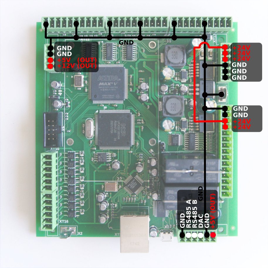
In this example, we will be showing the setup process for a Delta VDF-EL to myCNC. The Modbus communication will be using three wires - on the controller side, you will need to connect the RS485A, RS485B and GND contacts:
On the VFD side, you will need to connect SG+, SG- и GND, which can be found in the RG45 block. Counting from the right, pin #3 is GND, pin #4 is SG-, and pin #5 is SG+.
Connect GND to GND, RS485A to SG+, and RS485B to SG-.
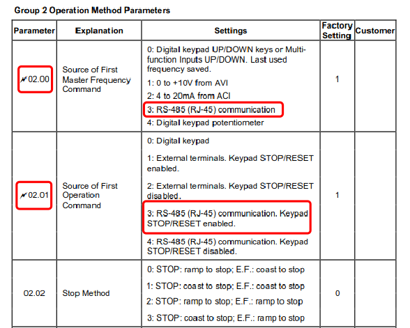
Next, we need to alter some settings within the VFD. For the Delta EL, this will be:
- 02.00 – 3;
- 02.01 – 3;
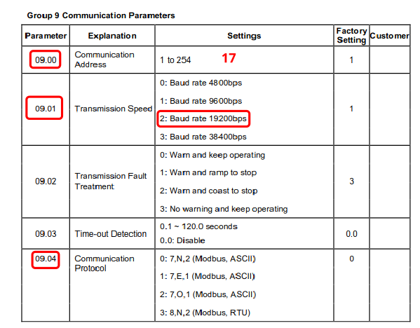
- 09.00 – 17 (any value from 15 to 254);
- 09.01 – 2;
- 09.04 – 6.
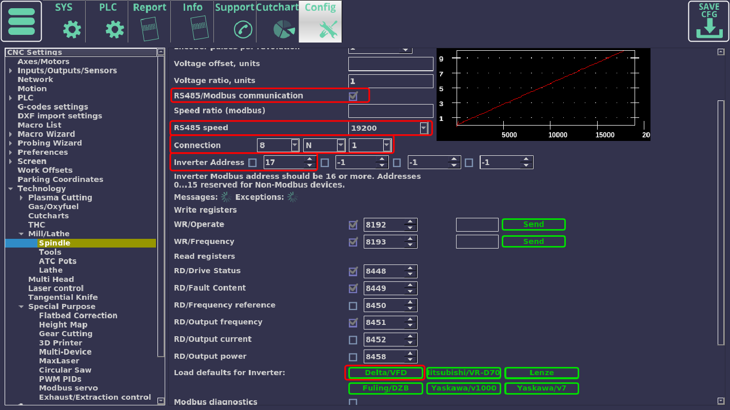
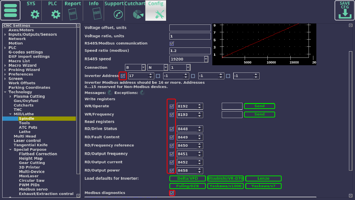
Open up the Technology > Mill/Lathe > Spindle tab in myCNC Settings.
- Set the check mark toggle to ON for RS485/Modbus communication.
- In the
RS485 speedfield, select the 19200 value; - Select a connection of 8 N 1;
- In the Inverter Address field, enter 17 (or whatever the value selected in 09.00 of the VFD);
- In the
Load defaults for inverterfield, press the“Delta/VFD”button.
After this, the correct register addresses should be displayed in the registers above.
- Toggle the check mark next to the selected inverter address as well as the check marks next to the inactive registers and Modbus Diagnostics fields.
After this, the Messages animation should begin to run, and the Modbus Diagnostics window should display confirmation messages (in red and blue) indicating that some sort of a connection ahs already been established. At this point, it is the matter of fine-tuning our configuration.
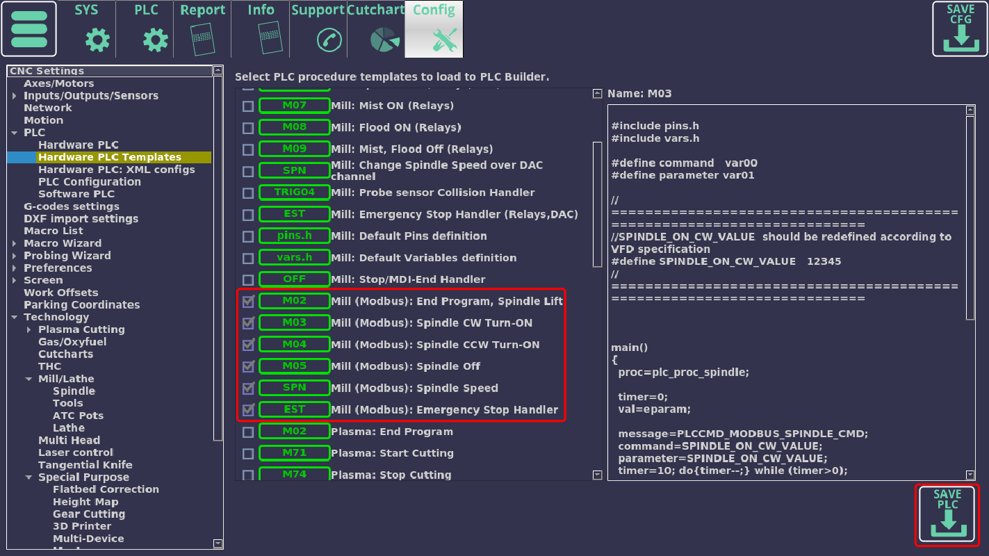
- Next, open the PLC > Hardware PLC Templates tab in myCNC Settings and put a check mark next to the M02, М03, М04, М05, SPN and EST procedures which are used for Modbus connections.
Press the “Save PLC” button in the bottom right corner and confirm the replacement of the existing procedures with the new altered ones.
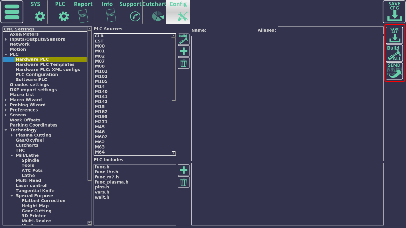
- At this point, we can head into the Hardware PLC tab and change the necessary PLC procedures to establish communication. For this, we will change some values in the M03, M04, M05 and EST procedures which will be written to the proper registers of the VFD.
- In the M03 procedure, locate the line
#define SPINDLE_ON_CW_VALUE 12345and change the default 12345 value to 18; - In the М04 procedure, locate the line
#define SPINDLE_ON_CCW_VALUE 12345and change the default 12345 value to 34 - In the М05 procedure, locate the line
#define SPINDLE_OFF_VALUE 12345and change the default 12345 value to 1; - In the EST procedure, locate the line
#define SPINDLE_OFF_VALUE 12345and change the default 12345 value to 1.
After this is done, press the “Build All”, “SEND” and “Save ALL” buttons at the top right side of your screen, and confirm that the PLC procedures have been successfully saved.
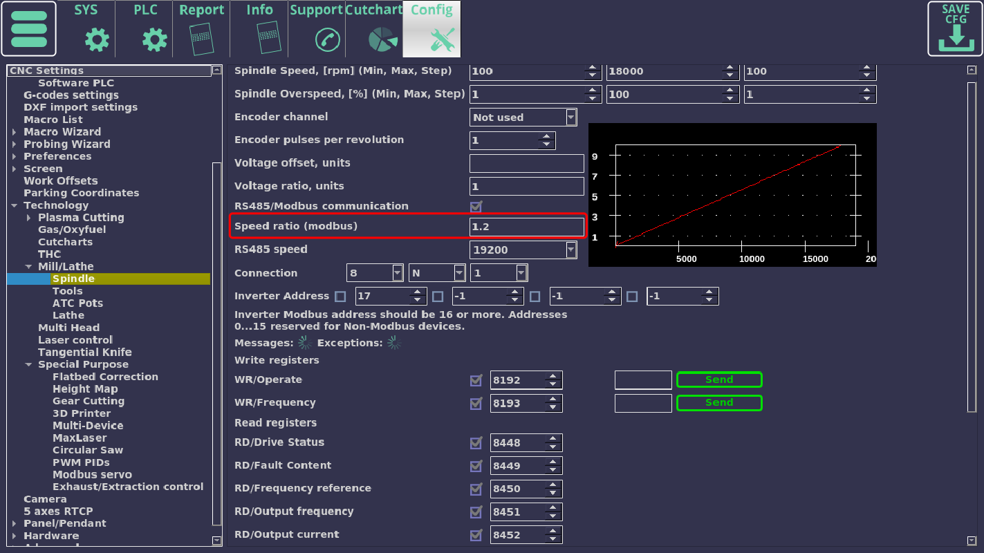
Now, when the М03 from the main screen is pressed, the spindle will start rotating clockwise, and when the M04 button is pressed, the spindle will start rotating counter-clockwise. It should also respond to changing the rotation speed. If the observed rotation speed is not equal to the theoretical (expected) rotation, this can be adjusted by using the coefficient in the Speed ratio (modbus) field in your Settings.
At this point, the setup should be complete.
Other systems
WK600
NOTE: This information has been compiled by myCNC users, and may be inaccurate. It is provided solely to aid clients in their setup for purposes of demonstration.
Specifying the parameters:
- PD-00 — 6 (speed 19200)
- PD-01- 3 (data format 8.N.1)
- PD-02-17 (local address)
- PD-03-2 (response wait time)
- PD-04-0.1 (connection duration timer)
- PD-05-1 (standard protocol)
- PD-06-0 (current resolution, in 0.01А )
Registers:
- Inverter start/stop — int 8192 DEС (2000Hex) 1 — start forward, 2 start backwards, 5 stop (write-only)
- To set up frequency via Modbus, register int 4096 DEС (1000HEX) 0 — 100.00%. (read-write)
- Status — int 12288 DEС (3000HEX) — 1 run foward, 2 run backwards, 3 stop (write-only)
- Current — int 4100 DEС (1004HEX).
- Error status — int 32768 DEС(8000HEX)
- Work frequency - int 4097 DEC (1001HEX)
- Work speed - int 4103 DEC (1007HEX)
- Write a “1” to М03 (instead of 12345)
- Write a “2” to M04
- Write a “5” to M05
