Table of Contents
Modbus Setup
This article is designed to introduce the reader to the myCNC Modbus setup, as well as serve as the main reference point for all myCNC Modbus documentation.
Note that on the ET10 control board, Port #1 (A/B) is used for all Modbus communication by default. Port #0 (A/B) is reserved for special purpose applications. Please contact the myCNC development team for implementing a special purpose application through port #0.
Low-level vs high-level access
Modbus communication can either be done through high-level access (especially useful for cases where using spindle control through an inverter such as a Delta VFD, Fuling DZB, etc), or through low-level access which allows the user to program the process via a PLC procedure.
High-level access is preferable for its ease of use. The settings for different inverters can be preloaded by going into Settings > Config > Technology > Mill/Lathe > Spindle, and the myCNC system will automatically attempt to send the message again should the sending fail (up to four times). For high-level access, please set the check mark to ON in the RS485/Modbus Communication field in the Settings > Config > Technology > Mill/Lathe > Spindle window.
Low-level access is preferable for direct access to the hardware. This allows to program the communication through PLC, and is a very flexible (albeit less straightforward) method. For low-level access the check mark in the RS485/Modbus Communication field in the Settings > Config > Technology > Mill/Lathe > Spindle window to OFF.
NOTE: The two modes are exclusive - low-level access will not work if the check mark is ON
and vice versa
I/O expand cards mapping
The transparent mapping of Modbus inputs/outputs can be done through the I/O Expand cards mapping window in Settings > Config > Inputs/Outputs/Sensors. In this part, the focus will be on expanding the number of inputs/outputs in a standard myCNC controller using a WELLPRO Modbus device. This process provides the user with a way to easily add 8 more inputs and 8 more outputs per Modbus device connected, allowing to connect more peripherals to the myCNC controller.
NOTE: In order for low-level access Modbus devices to connect properly,
the "RS485/Modbus communication" checkbox should be UNCHECKED in the
Config > Technology > Mill/Lathe > Spindle configuration dialog.
That checkbox is useful for high-level access only.
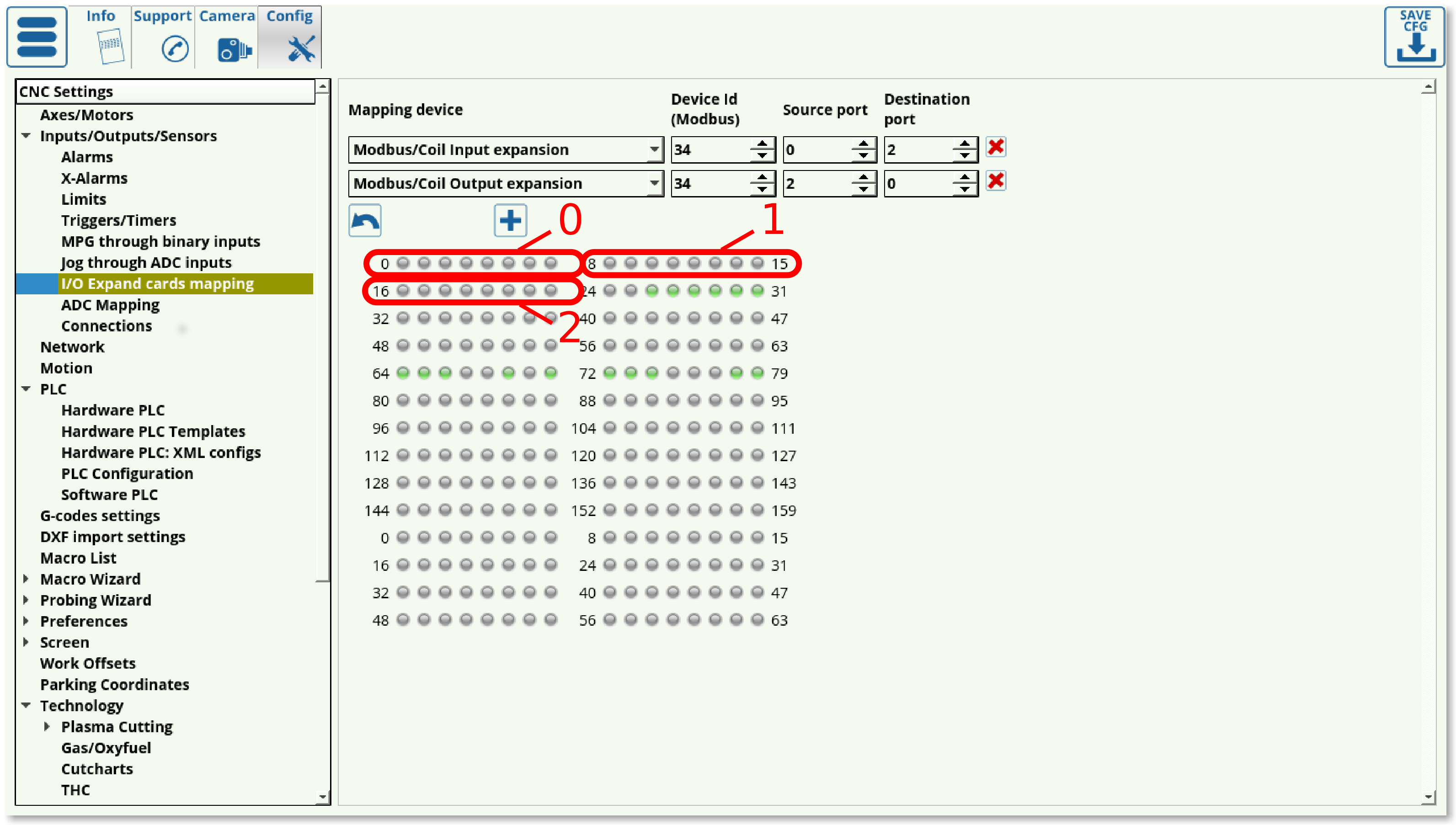
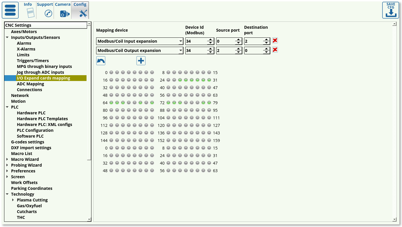
Upon opening the I/O settings, the following window is presented to the user:
In this window, the following settings can be edited:
Mapping device
For now, the focus will be on coil input/output expansion, which can be seen selected in the screenshot above. Therefore, Modbus/Coil Input expansion and Modbus/Coil Output expansion will be chosen in the Mapping Device selection.
Device ID
Device ID can be changed using PLC procedures using gvarset (60010,DEVICE ID); as described in PLC/Modbus API. If the device ID is unknown, the user can either switch it using the PLC procedure, or try to go through the possible Device IDs (0 through 255). The device ID has been previously assigned to be 34 in case of this example.
Source Port
Source port is usually chosen to be 0 for Input, as the count typically starts from zero on the Modbus device. This will signify the port from which the inputs are “carried into” the system. The way the ports are organized in the software is as follows:

As can be seen in the screenshot above, each port consists of 8 inputs, which are grouped together. These groups are numbered from 0 up.
Destination port
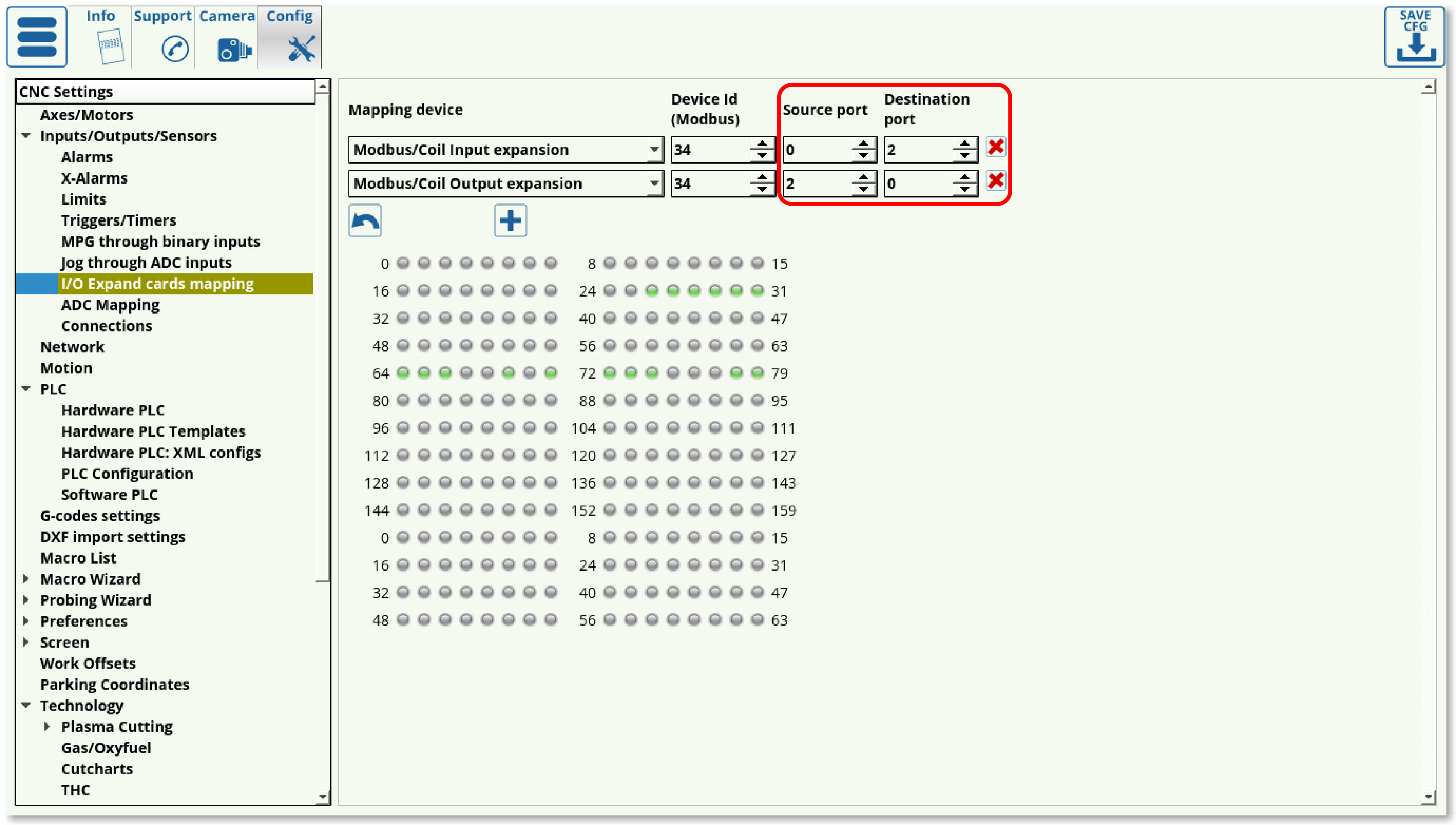
Destination port is the port to which the inputs are sent to. There is a number of assigned “virtual” ports in myCNC software which do not correspond to any physical ports on the controller itself. These virtual ports can therefore be assigned to the Modbus device for it to send its inputs to. In such a way, for Inputs expansion, the Source port can be set to 0 to correspond to the Modbus configuration, and the Destination port can be set to 2, 3, 4, etc in order to “fill” one of the virtual ports in myCNC software. Note that since the ET7, for example, has 16 inputs, the Destination port can be set to be 2 and above, while for the ET10 (which has 48 inputs) the virtual Destination ports start from 6 and above.
Input/Output behaviour switch
NOTE: The above description for the source/destination Input ports setup is reversed for the Outputs expansion. In the Modbus/Coil Output expansion, the Source port is the myCNC software virtual port, and the Destination port is the Modbus device. Therefore, the Source port for and Output expansion can be set to 2, 3, 4, etc, while the Destination port would be set to 0 to correspond to the numbering on the Modbus device (the source is the host/controller, while the destination is the Modbus rather than the other way around here).
This inversion results from the Source and Destination being effectively flipped when using input/output ports via a Modbus. With inputs, the source is the Modbus device, while with Outputs, the source is the host computer/controller.
Using the I/O Expand cards mapping window allows for a guaranteed signal delivery even if the Modbus device was turned off when the initial signal was sent (for example, when changing the Binary Outputs status from OFF to ON in the System Diagnostics window). However, a certain amount of latency (up to 100-200 ms) is introduced, as the system has to regularly loop through and check for the inputs/outputs on the Modbus device. Therefore, using I/O expansions via a Modbus device is recommended on systems which are less time-critical.
NOTE: The latency will increase as more mapping devices are introduced, as the system loops through each such device one at a time.
Using Modbus through PLC commands
The instructions for using PLC commands for a Modbus device can be found in the PLC/Modbus API article. As compared to the I/O expansion procedure through the Config settings, PLC commands eliminate the latency. However, the PLC method of using a Modbus device does not allow for device downtime, as is the case with the I/O method.
Using Modbus through Software PLC
The Host Modbus API is designed to be used with Software PLC. This allows to connect the Modbus device directly to the host computer through a USB port. This is a slower process than the Hardware PLC described above, however it is well-suited for repeated tasks which have to be constantly running, as it allows to offload the task from the controller onto the host computer.
Modbus Devices available
The detailed description of the available Modbus devices is located at the Modbus Devices page.
Example setups
General communication example
Sample M03 procedure for Spindle ON through Modbus
This M03 procedure can be found by going into Settings > Config > PLC > Hardware PLC Templates > Mill (Modbus): Spindle CW Turn-ON.
- As can be seen in the sample code, the
timeoutdelay is set to the spindle ON delay. This spindle ON delay is specified in the User Settings:
More information on controlling the spindle through Modbus can be found in the MyCNC Configuration Dialogs (Spindle) manual.


