Table of Contents
PLC/Modbus API
A number of Variables from Global Variable Array are mapped to Modbus interface. It's possible to setup Modbus device ID, communication parameters and speed, and access to device Modbus Registers by writing to this variables.
Mapped variables to access the Modbus devices are listed below:
| Variable Address | Description | Function code |
|---|---|---|
| 60010 | Device ID. Change Device ID | server command |
| 60011 | ASCII/RTU Switch. Change Modbus mode. "0" - Modbus/RTU "1" - Modbus/ASCII | server command |
| 60012 | Modbus bitrate. Writing to this register will change RS485/Modbus speed. Available speeds are 1200, 2400, 4800, 9600, 19200, 38400, 57600, 115200 | |
| 60013 | Communication parameters. Change UART connection parameters: number of bits (8 or 7), parity (none, odd, even), number of stop bits (1, 2). Data comes in 3 low nibbles. The lowest is stop bits, then parity, then number of bits. Example: 0x801=8,N,1 0x712=7,O,2 0x822=8,E,2 | |
| 60019 | Register Value. Writing to register will latch the value in shadow register. Value from shadow register will be used | |
| 60020 | Read Register Address. Writing to register will latch Address to read in shadow register | |
| 60030 | Write Register. Writing to register will send value from shadow register to Modbus devive to address given in written value on write operation | 16 |
| 60031 | Read Register. Read from this register will send read inquiry to Modbus device (PLC controller will be in Sleep till Register value received from Modbus device). Writing to this register will send ready inquiry to Modbus device. The value written is used as Register address to read | 3 |
| 60035 | Write multiple coils. Low 16 bits of the value indicates the address of the first coil should be written. The high byte of the value (value»24) indicates number of coils to write. The value latched in 60019 register will be sent to the device. | 15 |
| 60037 | Write single register. Write single register indicates address of the holding register and the new value of the register. The response, similarly, is the address of the register and the new value. | 6 |
| 60038 | Write single coil. Requests the 16-bit address of the coil, and the value to write (0 for OFF, FF00 for ON) | 5 |
| 60039 | Read multiple coils. This will request the address of the first coil to read and the number of coils to read. The Modbus device will respond with the number of bytes to follow and the coil input values | 1 |
| 60060 | Input register 0 | |
| 60091 | Input register 32 |
PLC code examples
main()
{
  gvarset (60010,40);    //Set Device ID (40)
  gvarset (60011,1);     //Set Modbus ASCII
  gvarset (60012,9600);  //Set bitrate 9600bps
  gvarset (60013,0x801); //Set communication parameters 8,N,1
  gvarset (60019,12345); //Set Value to write (12345)
  gvarset (60030,0x1001);//Write the Value (12345) to Register #0x1001
  gvarset (60035, 0x081001);//Write the value (12345) to register #0x1001
  gvarset (60037,0x64);  //Send value to address

  exit(99);
};
Switching the Modbus Device ID:
#include pins.h

main()
{

gvarset(60010,0); //addressed to all devices (0)
gvarset(60019,34); //the device ID will be set to 34 in this case
gvarset(60037,0x64); //sends the new device ID to the Modbus device

exit(99);
};
Below is a more realistic PLC example which involves a WP8028ADAM Modbus device (capable of reading/writing):
#include pins.h

main()
{
  gvarset (60010,34);    //Set Device ID (40)
  gvarset (60011,0);     //Set Modbus RTU
  gvarset (60012,9600);  //Set bitrate 9600bps
  gvarset (60013,0x801); //Set communication parameters 8,N,1


do{
timer++;

if ((timer&0x7f)==0) //how often the commands will be sent to the Modbus device
{
  read_address=0;
  gvarset(60020,read_address); //read register address

  in=gvarget(60039); //read multiple coils

  gvarset (60019,in); //latches the values in the shadow register
  a=(8<<24)+0; //0 is the shift value here - can easily shift the input by writing a different number
  gvarset (60035, a);//Write the value
};

}while(1);

exit(99); //normal exit

};
Note that the commands to read multiple coils (the in variable) will not work for a Modbus device that can only write (outputs only). Similarly, the write commands will not work on a Modbus device with inputs only, such as the WP8026ADAM. Below is a list of available Modbus devices and their capabilities:
| Device | Description |
|---|---|
| WP8028ADAM | 8 digital inputs, 8 digital outputs |
| WP8027ADAM | 16 digital outputs, 0 inputs (write-only) |
| WP8026ADAM | 16 digital inputs, 0 outputs (read-only) |
| WP8025ADAM | 8 relay outputs (normally open) |
| WP9038ADAM | 6 analog inputs, 4 digital inputs, 4 digital outputs. The digital inputs/outputs work similarly to the WP8028 |
Modbus Scheduler in myCNC has 4 messages queue. Up to 4 registers can be written immediately from PLC procedure. Modbus manager will send it one-by-one and will be waiting a reply from Modbus device after each message.
Modbus manager will repeat the message to device up to 4 times in case no reply is received within 250ms.
Important!
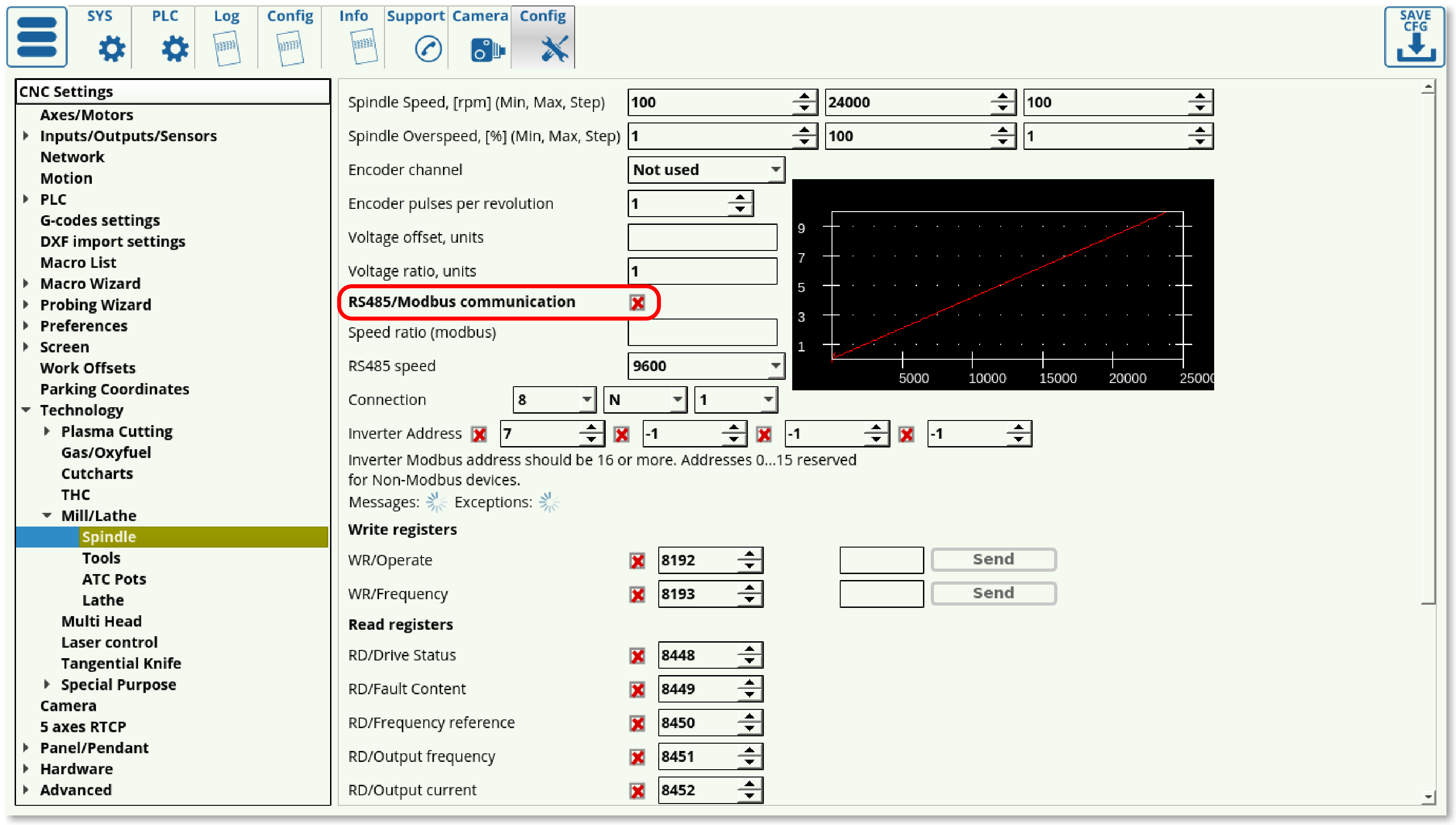
If the Modbus device is controlled directly from the PLC procedure, "RS485/Modbus communication"
checkbox should be UNCHECKED in Settings > Config > Technology > Mill/Lathe > Spindle
configuration dialog

