Table of Contents
MyCNC Configuration Dialogs
NOTE: A more compact version of this manual is available here, for ease of topic navigation.
Axes/Motors
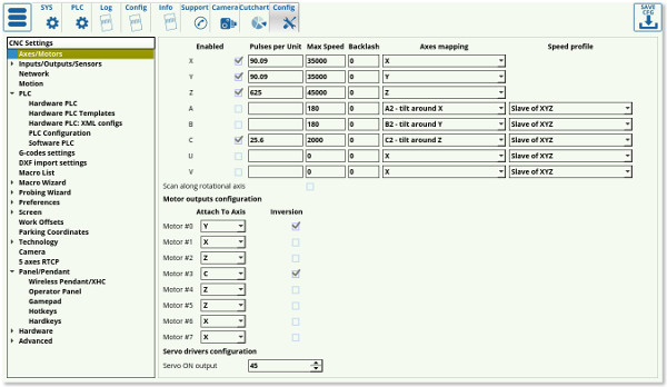
The main axes-motors parameters can be configured in the settings by going to CNC Settings > Axes/Motors
- Enabled. Each of the motors for axes X,Y,Z,A,B,C,U,W,V can be enabled or disabled. If any axis is disabled the software ignores All coordinates for this axis and does not send any motion to this axis. It is convenient to disable the axes you don't use on your particular machine.
- Pulses per unit. This parameter sets the number of pulses which the controller sends to the motor drivers to move by 1 unit distance (the unit depends on CNC configuration and can be either “mm” or “inch”). The full instructions on pulses per unit setup can be found on the QuickStart page here.
- Max Speed - CNC control will limit machine speed for each axis by this value. Note that the Max Speed does not count the override % value. Be careful if you use override values more than 100%
- NOTE: Overspeed acts in a manner similar to CPU overclocking. Motion acceleration is increased together with motion speed when the overspeed is increased. Since toolpath planner does not have access to “Overspeed” value, a significant increase in Overspeed value up from 100% may cause issues, especially for analog servo control. Overspeed should be limited to 100% if you need to be sure the machine does not exceed “Max Speed”.
- Backlash - Backlash value in units (mm/inch) for each axis (different for each machine depending on the hardware specifications). Backlash is defined as the movement of the motor which may turn slightly before any actual axis movement is present (caused by gaps between parts).
- Axes Mapping - Toolpath planner uses this setting for tool motion speed calculation. Possible settings are-
- “X”, “Y”, “Z”, “U”, “V”, “W” - linear axes X, Y, Z, U, V, W
- “A1”, “B1”, “C1” - rotation around axes X, Y, Z. Tooltip makes a circle-like motion on a material surface while the A/B/C axis is turning (a rotary table, 4th rotary axis, etc).
- “A2”, “B2”, “C2” - tilt around axes X,Y,Z. Tooltip position is not changed while the A/B/C axis is turning. Only the tool orientation is changed (a rotating tangential knife, a 3D plasma bevel head, etc).
- “Linear axis” - additional linear axis (any linear axis the behaviour of which cannot be described as an X/Y/Z/U/V/W axis)
- “Rotary axis” - additional rotary axis (any rotary axis the behaviour of which cannot be described as an A/B/C axis)
- Speed profile - additional settings to optimize Speed profile for rotary axes
- “Constant surface speed” - Tooltip is moving on the surface of turning material. Turning speed is calculated depending on the given F-feedrate and the tooltip cutting speed on the surface (It's supposed that a tooltip is moving in an arc motion with radius depending on current XYZ position).
- “Slave Of XYZ” - Current speed calculated for X,Y,Z axes depending on a given F-feed rate. Turning speeds for rotary axes are adjusted to get synchronous motion.
- “Spherical correction” - Settings for 3D bevel cutting head and RTCP kinematic correction.
- Attach to axis. Any of 6/8 motor output can be attached to any axis. Here you can select what axis is used for every motor output. Note the option of X+Y and X-Y axis attachment - this particular configuration has been designed for a belt system which uses two motors to drive the machine.
- Inversion - Mark the checkbox if you need to change the rotation direction for any axis. That way the system will invert movement in the negative direction to be registered as positive, and vice versa.
For Dual axis configuration just attach one axis simultaneously
to two (or more) motor outputs. For example, in the picture above,
Motor outputs #0 and #1 are used for X-axis. Inversion is selected
for Output #1, so both motors connected to Output#0 and Output#1
will be rotated simultaneously, but in the opposite direction
Inputs/Outputs/Sensors
Alarms
myCNC software supports a number of Alarm inputs.
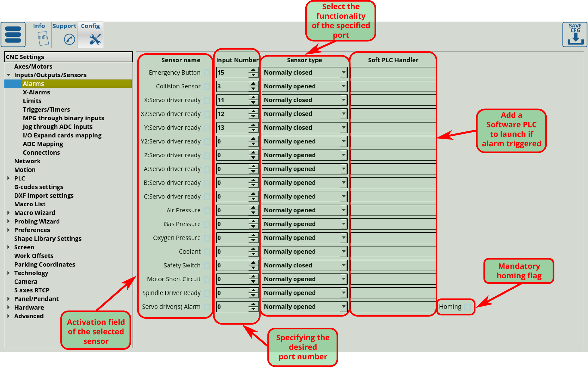
Any of myCNC controller binary input can be programmed as Alarm input. Alarm inputs setup is available in Alarms configuration dialog. In the dialog -
- Each Alarm can be enabled or disabled
- Any binary input can be assigned as selected Alarm
- Input type Normally opened or Normally closed can be selected to the alarm to specify its default behaviour while not triggered. The default behaviour can be checked in the Diagnostics panel and can be inverted in Settings > Config > Hardware > Common Hardware Settings.
- The program can also launch a Software PLC command when an alarm is triggered, by specifying a Software PLC handler in this Soft PLC field.
MyCNC software has different Handlers for each Alarm.
The following alarms are available:
- Emergency Button
- Collision sensor
- Please note that although although the functions might seem to overlap for some use cases, the collision sensor is set up as a different item in the myCNC settings from the probe sensor. The probe sensor should be set in Probing Wizard > Probing Config.
- X: Servo Driver Ready
- X2: Servo Driver Ready
- Y: Servo Driver Ready
- Z: Servo Driver Ready
- A: Servo Driver Ready
- B: Servo Driver Ready
- C: Servo Driver Ready
- Air Pressure
- Gas Pressure
- Oxygen Pressure
- Coolant
- Safety Switch
- Motor Short Circuit
- Spindle Driver Ready
- Servo driver(s) alarm
A full manual on the topic is available here: alarms
Emergency Button
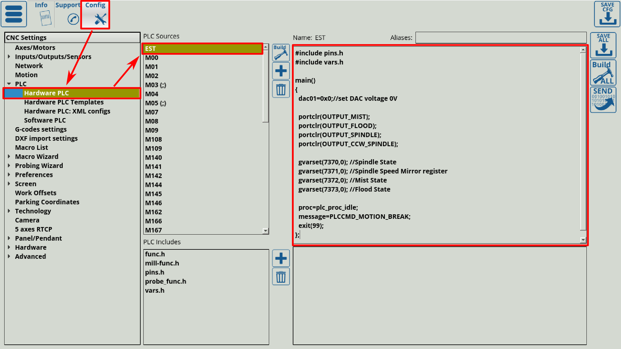
If Emergency button Alarm is triggered, the myCNC software stops running any Motion program or Jogging and Run PLC Handler for Emergency alarm - “EST.plc” PLC procedure.
When Emergency is triggered via the Emergency Stop button press, the execution of the control program stops automatically. At this point the “EST” Hardware PLC is started, with some predefined actions that will be performed (this can range from turning off the power supply, servo control, turning off the spindle, etc).
The user can define any behaviour or action for Emergency Stop event such as:
- Power off servo-drivers
- Power off Spindle/Plasma power source
- Switch Off coolant, mist, air
- etc.
PLC procedure “EST.plc” is available in PLC Builder/Hardware PLC. After editing the PLC procedure, press the “Save All”, “Build All” and “Send” buttons for the changes to take effect:
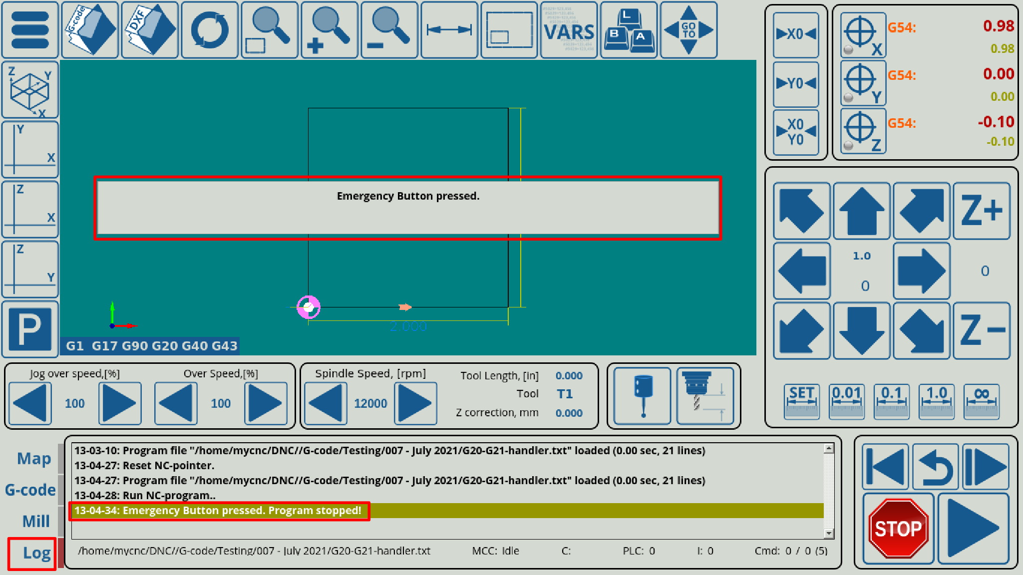
If Emergency button is activated, all further Job running, or jogging will be locked. An “Emergency button pressed” message will be shown on the main screen and in the Log window:
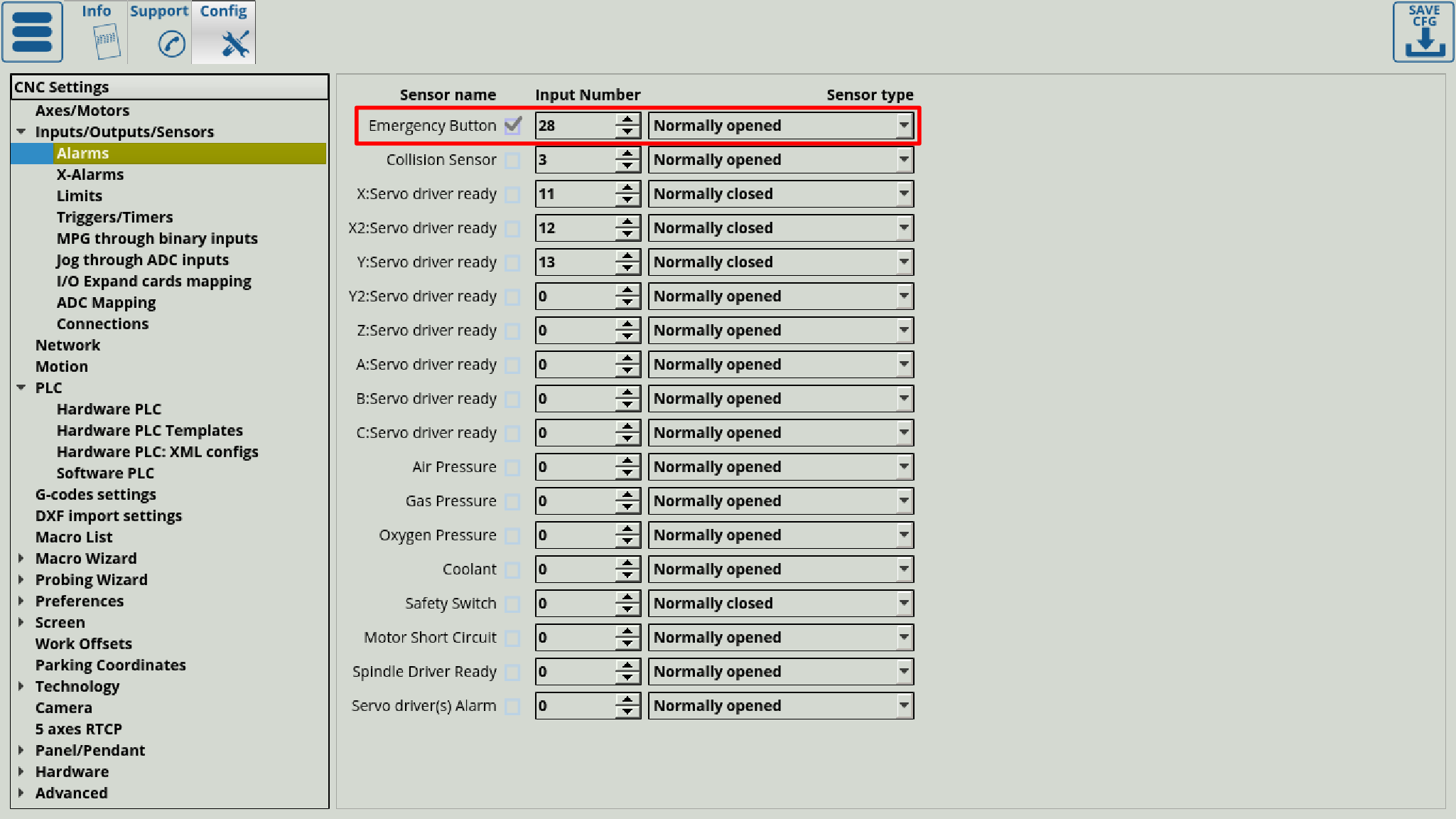
To configure the input port that will be assigned to the Emergency Stop button, please enter the necessary port value in Settings > Config > Inputs/Outputs/Sensors > Alarms. An example of Emergency button configuration is shown in the picture below:
- Emergency button is enabled
- Binary input #28 is used as an Emergency key
- Emergency button is Normally opened, an Emergency event will be activated if the button is closed
X-alarms
A more flexible alarm system, currently under development.
 This setting is recommended for users with unconventional cutting setups (such as complex plasma cutting machines with multiple sensors).
X-alarms allow to select the Input Number, the Type of input (normally open or closed), the process that the alarm triggering will be blocking (jog, job, PLC, or a combination of the three), as well as the Hardware/Software PLC Handlers which are summoned whenever the alarm is triggered. Due to being able to create unique PLC procedures, this alarm system can be customized to a much higher degree than the current alarm system which mostly deals with simple use cases.
As the system is currently under development, not all features are yet present or will behave correctly. Stay tuned for further updates.
Limits
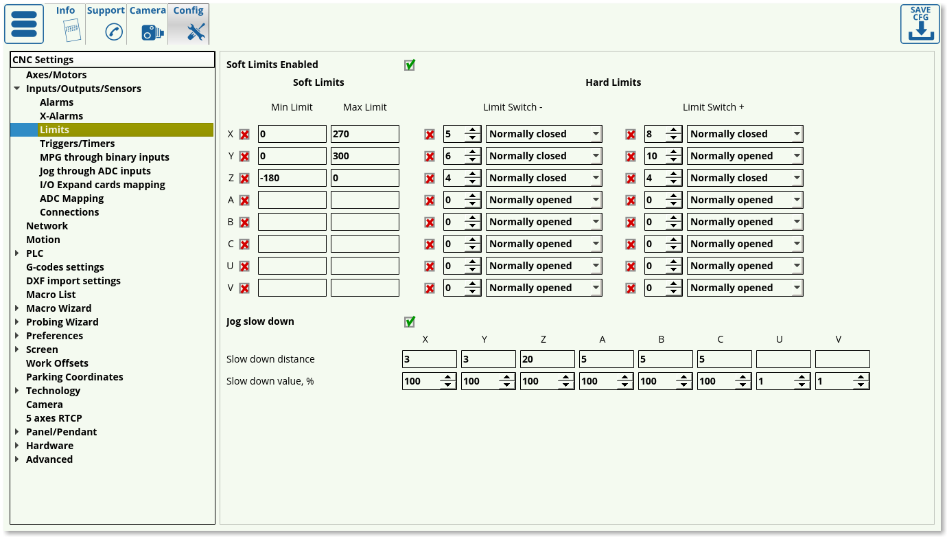 To configure the software limits:
- Check the “Soft Limits Enabled” checkbox
- Set ON the checkboxes for each axis you'd like to enable limits for
- Set the Minimum and Maximum range for each axis
- Press the “Save” button to save the settings
It is also possible to reduce the jog speed near the limits to prevent an abrupt stop when the limit is reached by the machine. If the operator moves the machine towards the software limit, the jog speed will be reduced beginning at a set distance from limit to a given value (in % of normal jog speed). To enable this option:
- Set “Jog slow down” checkbox
- For each axis, indicate:
- “Slow down distance” - the distance from the software limit when jog speed will begin to slow down
- “Slow down value, %” - Slow Jog speed (in % of normal jog speed)
- Press “Save” button to save the settings
For example:
Slow distance = 50, Slow value= 20%
If the operator moves the machine towards the software limit and distance to the limit is less than 50mm, jog speed will be 5 times less than the normal jog speed (20%)
Slow distance = 10, Slow value= 100%
No reduction in speed (because the slow jog value is 100% of the regular jog speed)
Besides having general software limits, hardware limits can also be configured in myCNC software. This is done by using a switch for the negative and positive direction of each axis which can be reserved within the myCNC software. Any switch can be enabled, and then assigned to any of CNC control board binary input and configured as “Normally Open” or “Normally Closed”. To enable the hardware limits for any selected axis:
- Choose the axis (X, Y, Z, A, B, C) and side (positive or negative) and set the respective checkbox to ON
- Set the input number for any of the switches connected
- Choose the sensor type to either be Normally Closed or Normally Open to specify the default behaviour of the switch
- Press the “Save” button to save your settings
Triggers/Timers
Triggers allow the software to interpret the sensor data depending on the sensor behaviour or the current position in the control program.
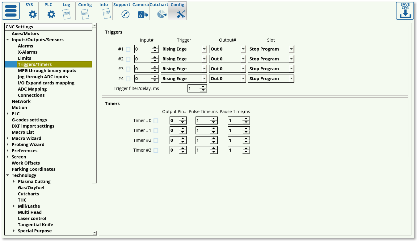 The settings that can be assigned to the triggers are the following:
- Enabled/disabled toggle to specify whether this particular trigger is on/off.
- Input number to indicate which particular input the trigger is bound to.
- Trigger behaviour (rising/falling edge). The trigger does not check for the actual status of the sensor, but rather for the change in status. This way, if rising edge is specified, the trigger will be initiated when the sensor goes from OFF to ON (rising), and similarly, the trigger will be prompted if the falling edge has been specified when the sensor changes from ON to OFF.
- Output number specifies which output port is bound to the trigger prompt. This feature remains from the earlier versions of the software.
- Slot specifies the result of the trigger being prompted. Usually, the Stop Program option is chosen, however custom trigger responses can be written as PLC commands (such as TRIG04)
Timers serve as a way to use the controller rather than the computer for timing tasks. The following settings can be specified:
- Enabled/disabled toggle.
- Output pin number to specify which pin is bound to the timer
- Pulse time, in order to set how long the process tied to the output pin (such as a coolant system) will be ON
- Pause time, in order to set how long this process will be OFF
MPG through binary inputs
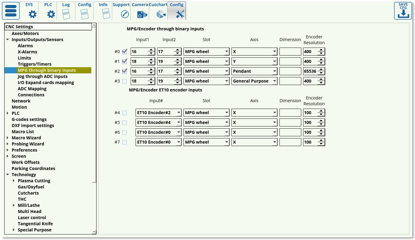
These settings allow the user to set up the manual pulse generator behaviour.
The following settings can be modified:
- Enabled/disabled toggle for each MPG
- Input ports number (2 ports needed for an MPG).
- Slot can be changed between MPG (to move the spindle around), THC/Z axis offset for manual control of the z-axis during torch height control, or Spindle Sync to synchronize the vertical z-axis movement and the rotation of the spindle.
- Encoder resolution: number of encoder markings per rotation * number of impulses per marking
As the ET10 controller has dedicated input ports for manual pulse generators, it is not needed to specify 2 different ports but rather one dedicated encoder port number for an ET10 setup.
NOTE: The ET7 controller has the two encoder slots reserved for the ET7 keyboard panel. These are permanently assigned to inputs #16, #17, #18, and #19, and changes in the Config window will not override this preset. If encoder slots are to be used on an ET7 board, the latter two are recommended. This setting is not present on the ET6/ET10/ET15 boards, where encoders 0-3 can be all used.
NOTE #2: The ET10 controller can utilize inputs 0-31 for its binary inputs for an encoder setup. IN32-39 are reserved and are not suited for binary input configurations with an MPG wheel etc.
The full MPG though binary inputs manual is available here.
Jog through ADC inputs
This function is useful to set up a joystick in order to regulate the speed at which the machine's working tool moves through analog means, allowing for more granular controls.
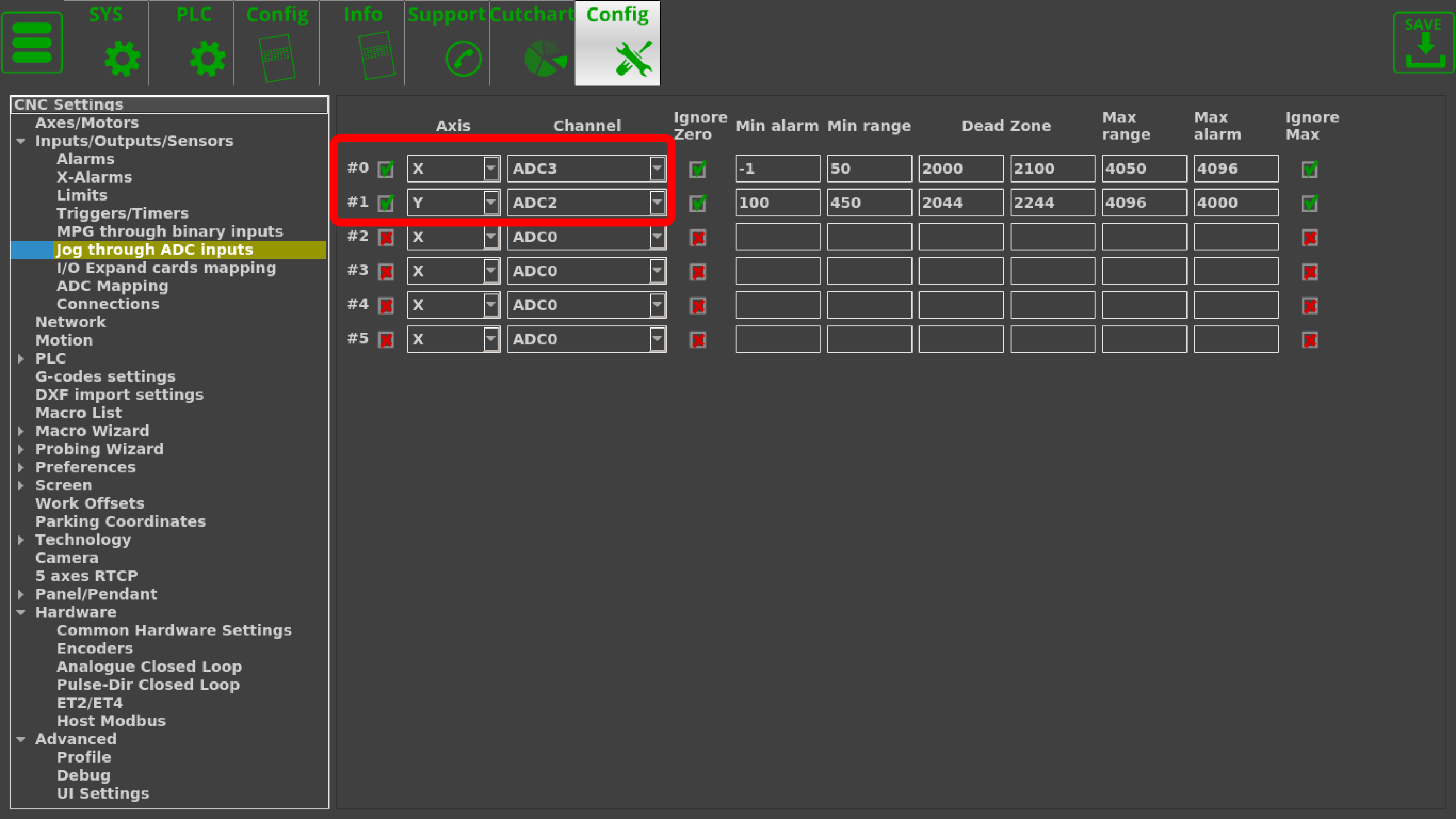
In order to do so, go to CNC Settings > Config > Inputs/Outputs/Sensors > Jog through ADC inputs. The following screen will be presented to you:
On this screen, we can set up the joystick inputs to adhere to the physical configuration and specifications of the joystick.
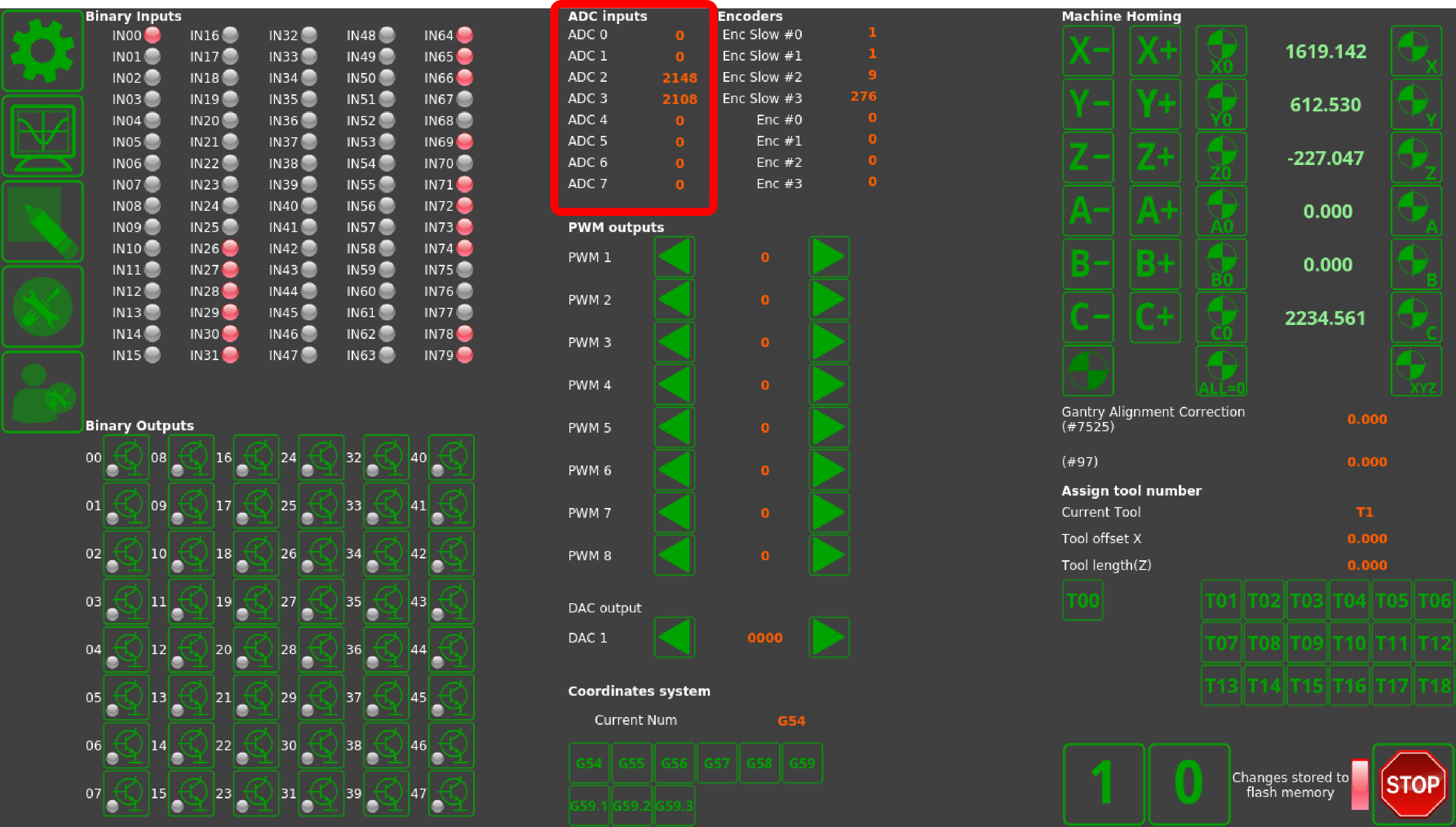
After connecting the joystick to the ADC ports of the controller, we can open the System Diagnostics window to check the actual ADC inputs.
While on the system diagnostics screen, move the joystick around to check which axis corresponds to which ADC input channel. In this example, ADC2 corresponds to the y-axis, while ADC3 corresponds to the x-axis movements of the joystick. These values are inputted back on the Settings screen:
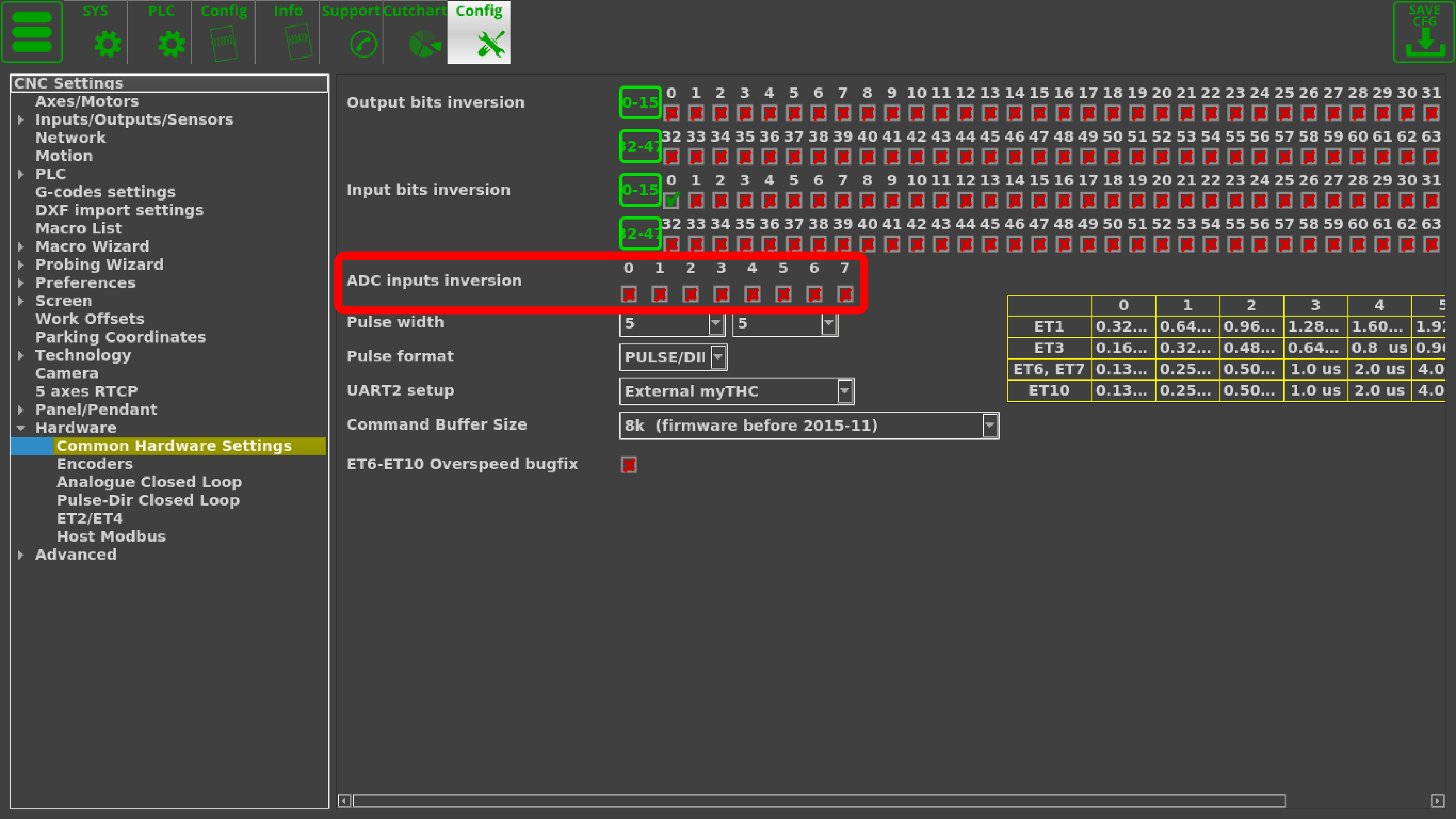
NOTE: If the axes for the joystick need to be inverted for any reason, this can be done in Settings > Config > Hardware > Common Hardware Settings
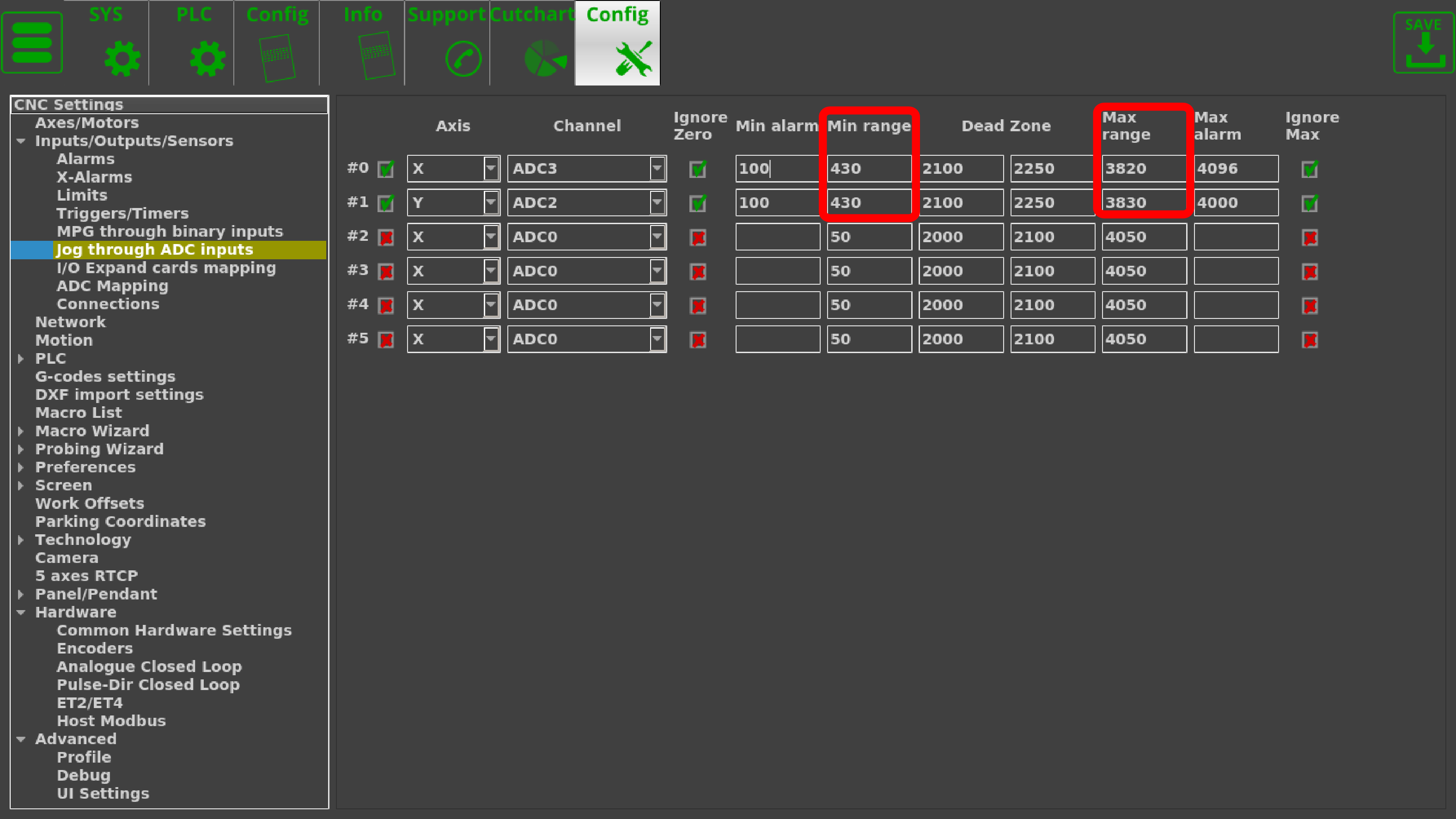
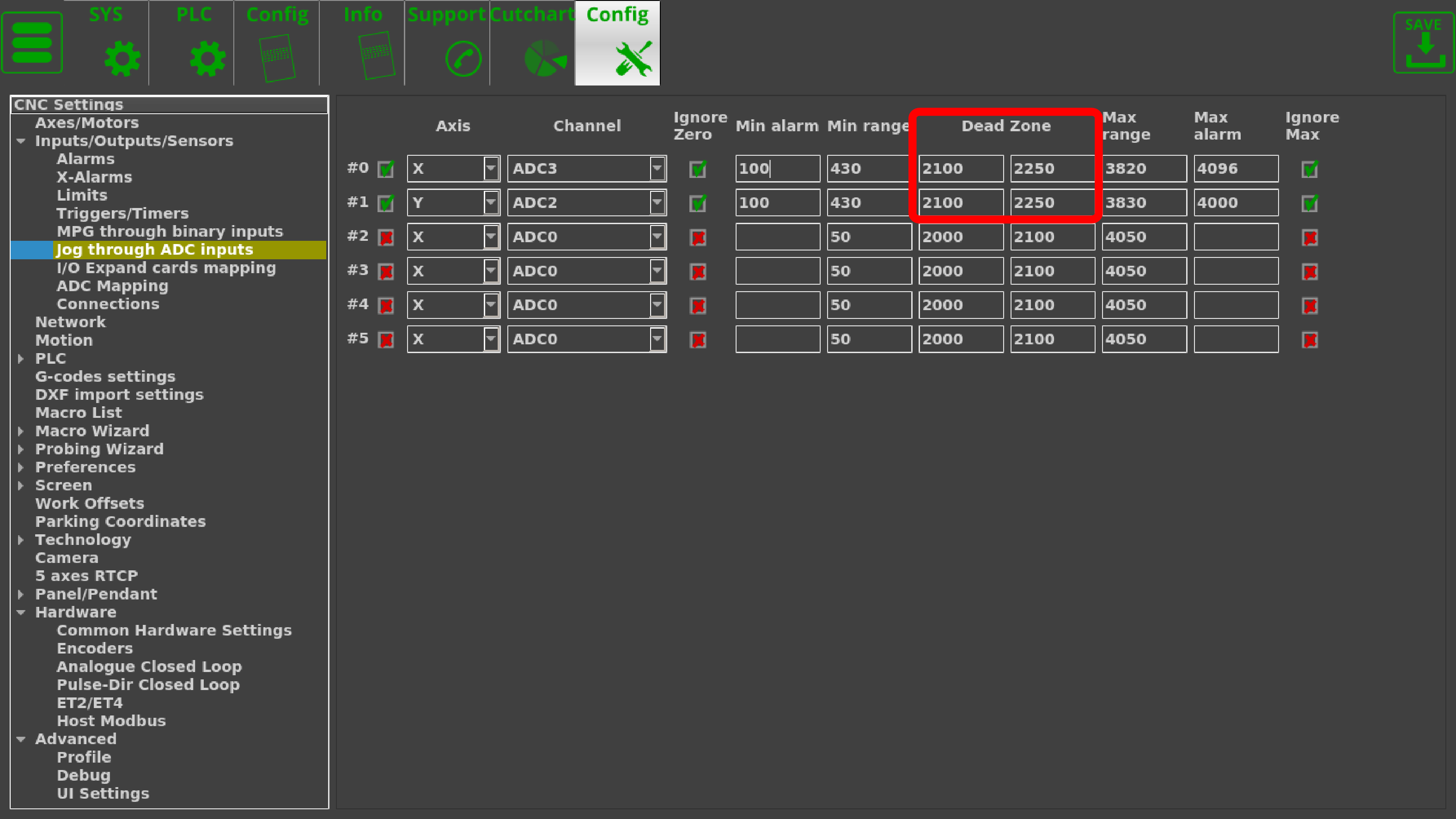
By moving the joystick the furthest it can go in all directions and noting the maximum and the minimum values, those can be set as the Max and Min range in settings. In this example, the joystick Min Range is equal to roughly 430 for both the x- and y-axis inputs, and is around 3820 for the Max Range of the x-axis and 3830 for the Max Range of the y-axis:
The Dead Zone is set to be from 2100 to 2150 for the joystick used in this example, as this is taken to be the zero position by letting the joystick return to its center. This value has a range so that small accidental movements of the joystick do not trigger the movement of the machine:
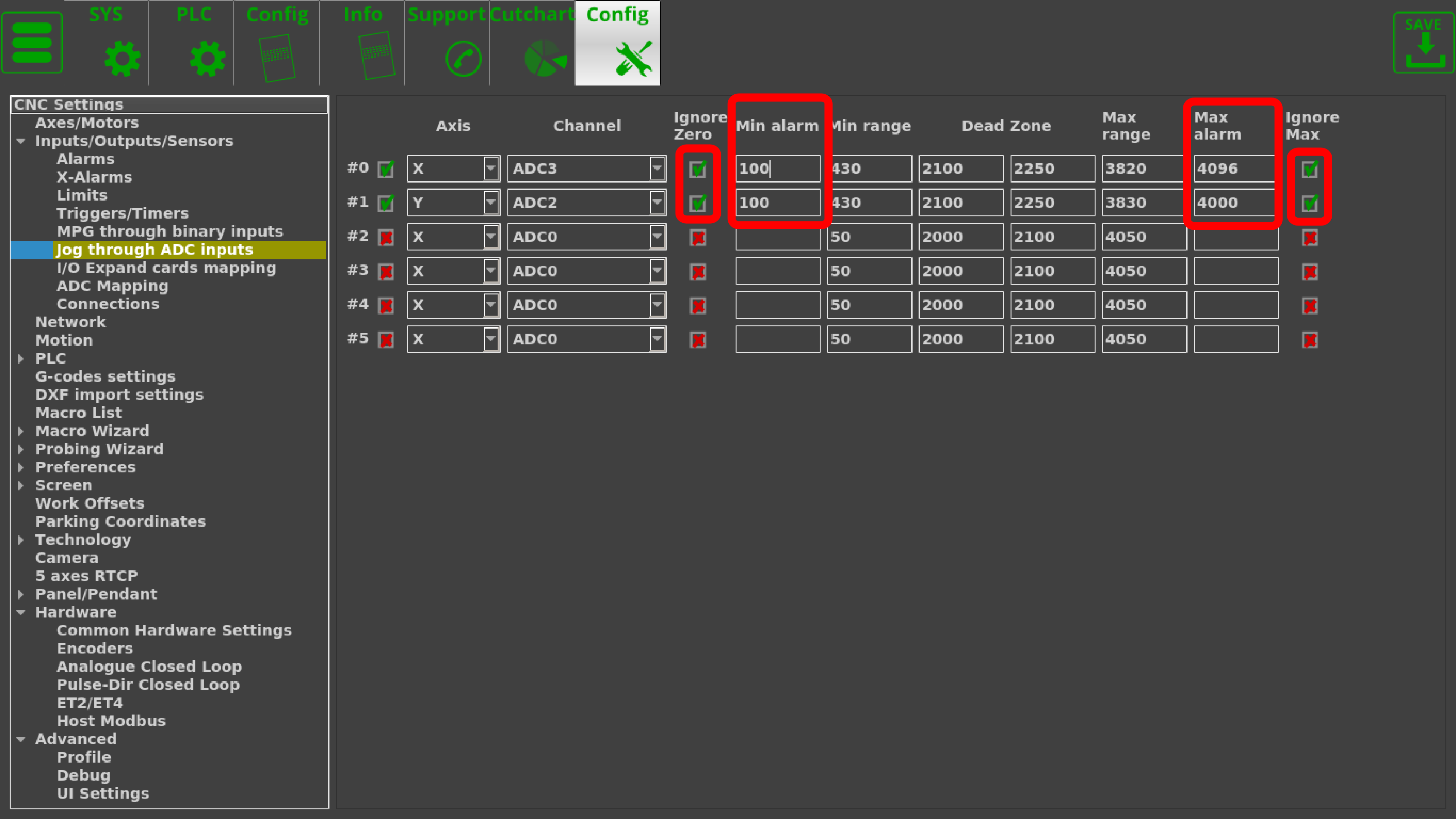
As this joystick does not drop to zero for its minimum range of inputs, it allows us to set up a failsafe in case the joystick is accidentally unplugged. In order to do so, both checkmarks for the Ignore Zero and the Ignore Max have been switched to green, and the Min Alarm and Max Alarm have been set to be slightly outside the Min and Max Ranges (however, the Min Alarm is ALWAYS set to be above zero in this case):
NOTE: Not all joystick controllers allow to set the failsafe Min Alarm properly.
Please consult your joystick manual to find out if the input values do not drop to zero
so that the failsafe can be set up correctly.
The full settings window then looks as follows:
I/O Expand cards mapping
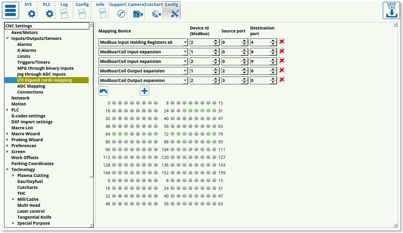
This window is part of the Modbus devices settings. Please consult the Modbus Setup article for a full overview of the options available.
The following options are available for the mapping devices:
- ET10 encoder inputs
- Modbus/Reg Inputs expansion
- Modbus/Reg Outputs expansion
- Modbus/Coil Inputs expansion
- Modbus/Coil Outputs expansion
- ETxx Inputs
- ETxx Outputs
- Modbus Input Holding Registers x2
- Modbus Input Holding Registers x4
- Modbus Input Holding Registers x6
- Modbus Input Holding Registers x8
ADC mapping
A full manual on the subject is available on the ADC Mapping page.
The following settings are available to the user:
- Mapping Port #. Check the box next to the selected port that you will be using.
- Source Type/Number. This selects the counter number to which the sensor is connected. Refer to controller documentation for the correct counter number, as that depends on the controller version.
- Destination Port Number. The destination port numbers begin from the next channel number after the real ADC channels present on the controller.
- Inversion toggle. Inversion can be useful in cases when the value from the sensor needs to be increasing as the distance increases, and vice versa. This flips the behaviour from the sensor readouts.
Please consult the full ADC Mapping manual for setup examples.
Connections
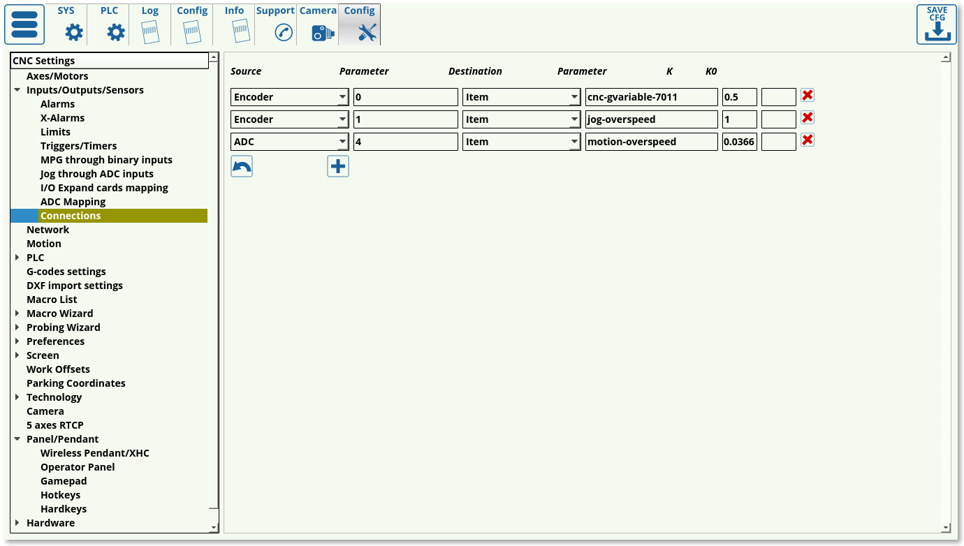
The connection settings window allows the user to create a connection between some input and some output, effectively binding some input to some response from the controller. Such a setup is useful to create a connection between, for example, turning the dial on an encoder and a change in the feed rate.
The connections tab outlines:
- the connection source (ADC, DAC, PWM, Input Pin, Input Port, Output Pin, Output Port, Encoder, Global variable, Item, XItem)
- source parameter
- connection destination
- destination parameter
- K values (ratio values) K and K0
The connection source is chosen based on the input that the user has selected (potentiometer for ADC, Encoder, etc). The connection destination specifies the designated input for that parameter (the number of the ADC input port, the encoder number, etc). The destination can again be chosen from a list of possible options, however Item is the one used frequently in order to make some changes in the myCNC software after some input has been received by the controller. The destination parameter will then specify the particular output that the connection will have. The ratio value K specifies the conversion factor which will be used to convert the input (input multiplied by K), while K0 specifies the shift in input (field usually left to be blank).
As part of the connection dialog setup, the Rotary encoder connection and setup manual goes in depth about the encoder settings and connection information. An abbreviated list of Items is available in the Common Items List.
Network
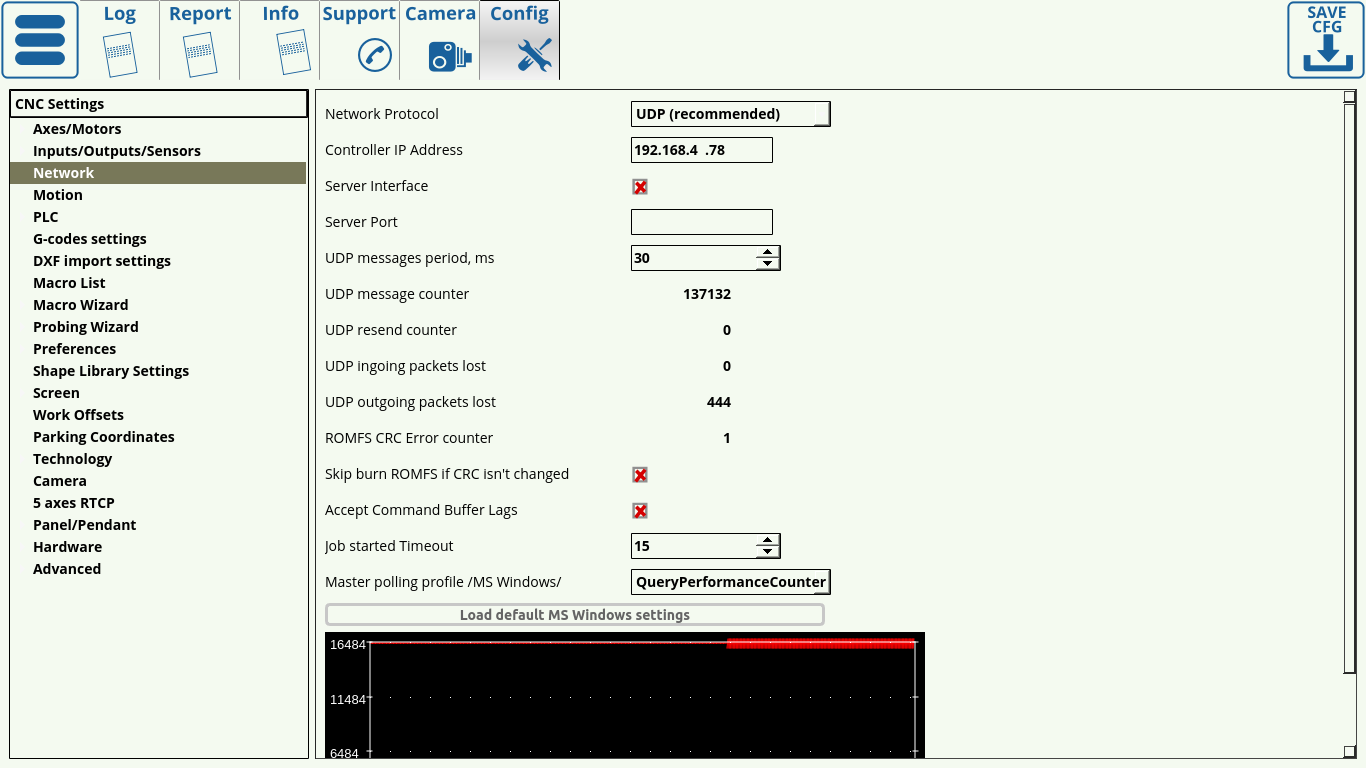
The Network tab is designed to help the user set up the connection with the controller. Upon opening the tab, you are presented with the following window:
- UDP is recommended as the network protocol, as TCP/IP is not used on the more recent myCNC controllers, and the Simulator mode is only able to perform simple tasks such as loading the program
- Controller IP Address specifies the IP address that the myCNC software will use to connect to the controller. Note that this address must be unique and different from your computer address for the connection setup to succeed.
- Server Interface and Server Port are used when it is necessary to connect to the program remotely. These can be disabled if there is no need for a remote connection.
- The UPD message period specifies the amount of time between each consecutive message sent to the controller. This is set to be 30 ms on Linux and 100 ms on Windows machines (which can be loaded using the “Load Default MS Windows Settings” button).
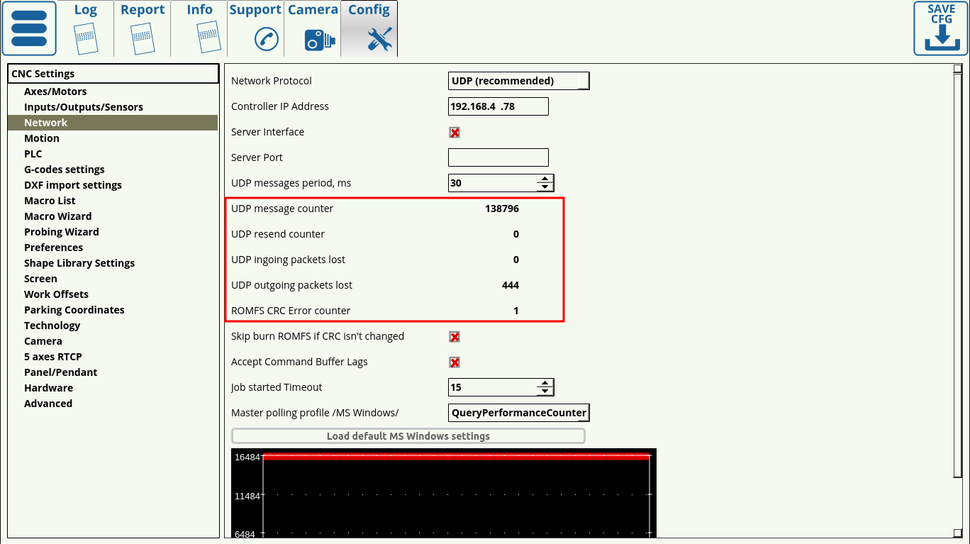
- The message/packets counters allow for quick diagnostics when using myCNC software. These indicate the number of messages sent, messages resent, as well as incoming and outgoing packets lost. Note that single digit packet loss is normal when first turning the controller/software on and as the connection is being set up since the message number that the controller expects will differ from the once sent from the myCNC software after restart. However, it is recommended to watch the packet loss number over some working time period (half-hour to an hour) to see if there is a constant packet loss occurring after the software setup has been completed. If continuous packet loss occurs, it indicates problems in the connection between the host computer running myCNC software and the controller.
- The Skip Burn ROMFS toggle allows to skip writing PLC onto the controller every time a new session is started. This can allow to reduce the start up time of the myCNC controller if no changes to PLC are planned to be introduced.
- Accept Command Buffer Lags toggles the acceptance of lagging commands that are sent to the controller despite the delay indicated in the command buffer window below. This is usually done when the number of commands per second is very large (in the hundreds/thousands), and can lead to unexpected jerks of the machine due to sudden speed changes. This setting is recommended to be used in an experimental fashion.
- Job started Timeout specifies the time (in messages sent) between the signal for job start and the maximum allowable point at which the controller has to send a signal back to the host computer to confirm that the job has indeed started. This is set to be 15 by default - setting it much lower will result in the controller not having enough time to send a response signal to the computer, while setting it much higher might result in the computer taking much longer to process each individual user command.
- While by default, the Job Started Timeout is set to 15 in many profiles, on newer installations (especially on single board computers such as Tinkerboards) it is necessary to set this value to around 30 for reliable communication. Otherwise, the program may refuse to start due to the controller not having enough time to send a response back to the computer.
- Master polling profile specifies the network connection behaviour in MS Windows setups. This is set to the GetTickCount() option, and should not be changed unless required.
- Load Default Settings buttons allow the user to load the default network configuration for MS Windows and Linux machines in one click. The only difference between the MS Windows and Linux configurations is in UDP Messages Period field, with 100 and 30 ms respectively.
Motion
Upon opening the Motion tab in Settings, you are presented with the following window:
The following settings can be edited in the Motion tab:
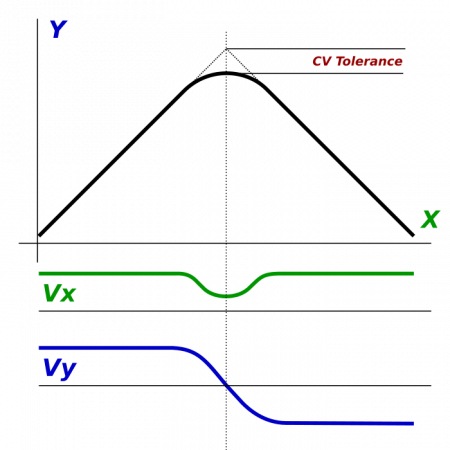
- CV Tolerance signifies the amount of “smoothing” on corners that is allowed at maximum, and is done in order to make the program go through corners faster instead of stopping at every sharp corner. As seen in the image below, the tolerance describes the distance from the “ideal” corner to the actual tip of the corner that the machine will produce.
- S-curve smooth filtering specifies the time the controller gives the machine to adjust its acceleration during sharp turns. A larger value allows for a larger impulse time, resulting in reduced stress and shocks to the machine hardware. 41ms is recommended.
- Acceleration Override allows the user to adjust how the acceleration behaviour works on the machine (from rapid changes to speeds at corners, which may cause the smoothness of the motor operation to suffer, to a smooth cut which will result in a longer time for the job to complete. This feature is currently under construction (as of myCNC v1.88.3943).
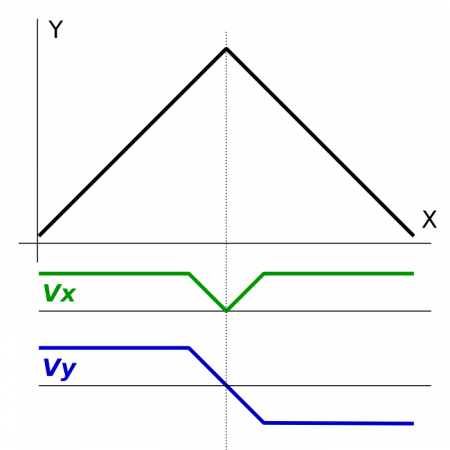
- Look Ahead Break Angle - if the angle is larger than this, the machine will stop at corner completely in order to allow for a sharper cut. An example of such a cut is shown in the image below:
- 2D Cutting is used on plasma/gas machines which lack a configurable z-axis. This option is turned OFF by default.
- Fast Cutting toggle - Allows to move over a part in a drawing process to check the movement path at a speed higher than the normal cutting speed. Useful for plasma/gas setups with a lower cutting speed. Writing 0 will disable fast drawing, writing 1 will enable fast drawing.
- Step-jog count specifies whether the user wants the machine to monitor the inputs sent to it as it is already moving or not. If selected, the machine will count however many signals are sent to it even if it is moving already, if not selected then the machine will ignore other signals until it has completed its initial movement. This allows to set up pendant control which will either count the number of impulses sent from the pendant and move an according distance, or will instead try to match the rotation speed of the pendant wheel (moving when the wheel is moved, stopping when the wheel is stopped).
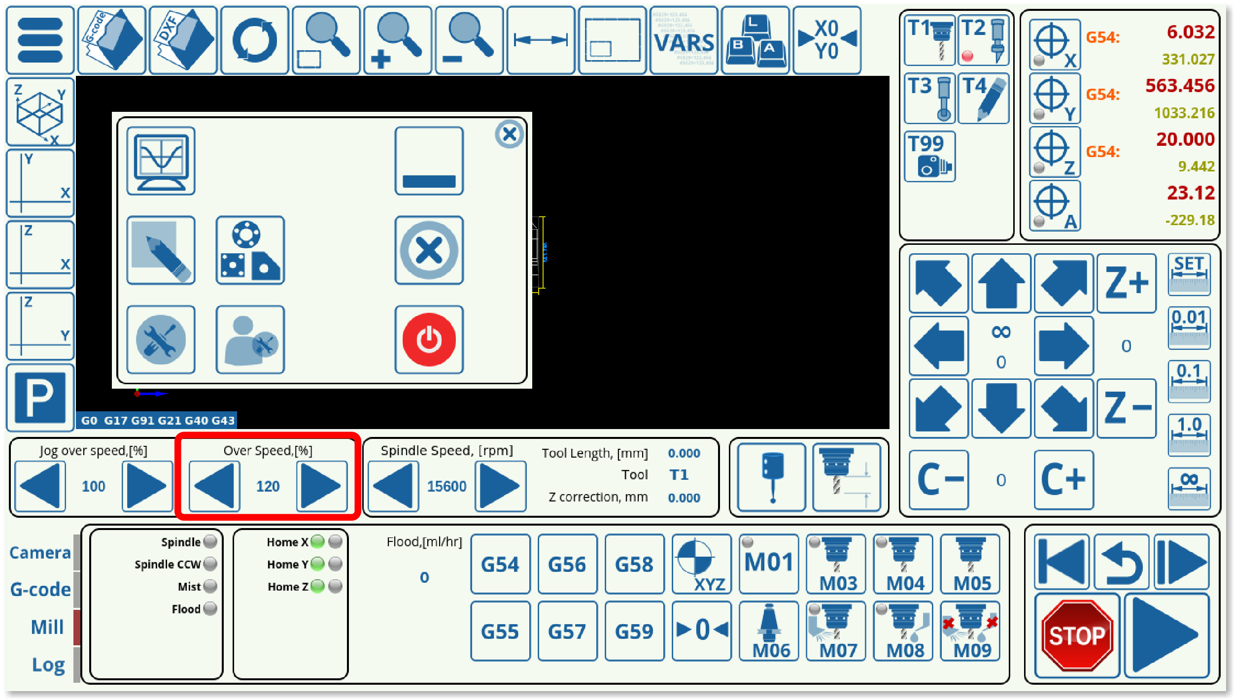
- Sync G0 & (G1, G2, G3) Overspeed allows the user to sync the rapid and cutting speeds, allowing the user to use one set of buttons (shown in the screenshot below) to change them at the same time. If the check mark in the Motion configuration dialog is set to ON, then upon pressing the Overspeed buttons on the main screen, both G1/G2/G3 AND the G0 Overspeed will be changed (speeds will be synced). If the check mark is set to OFF, only the G1/G2/G3 speeds will be changed upon pressing the main screen buttons, and controlling the G0 overspeed will be possible through the Motion dialog (see the Jog, G0 and G1, G2, G3 Overspeeds line below).
- NOTE: Overspeed acts in a manner similar to CPU overclocking. Motion acceleration is increased together with motion speed when the overspeed is increased. Since toolpath planner does not have access to “Overspeed” value, a significant increase in Overspeed value up from 100% may cause issues, especially for analog servo control. Overspeed should be limited to 100% if you need to be sure the machine does not exceed “Max Speed”.
NOTE: The ET6, ET7 and ET10 myCNC motion controllers have a typical overspeed range from 1% (low bound) to 125% (high bound). Setting overspeed to a value higher than 125% may lead to performance issues.
- Creep Speed specifies the speed of the machine after it begins to cut into the working material. It is advisable to set it to be lower than the actual working speed for a small portion of time at the start of the cut. This time is specified in seconds.
- This is a legacy option. Using creep speed / creep time allows to use a slow movement during the initial pierce of the material, resulting in less wear on the plasma or gas torch, allowing for the metal to fly out of the cutting area as the torch moves. Modern plasma torches allow for a more focused cut, rendering this option obsolete - however, it still may be used on older plasma machines or on gas cutting machines.
- Jog, G0 and G1, G2, G3 Overspeeds signify the value by which the speed is higher/lower than the one specified by the running program. This is useful so as to be able to change the speeds on the fly. The max and min values specify the speed boundaries, so if a certain boundary needs to be imposed, the operator cannot accidentally go over or under the max/min speed limits by using the sliders on the main screen. The step meanwhile indicates the increments by which the speed values change when the operator clicks the main screen sliders.
- Arc cutting
- Speed/Acceleration table allows the user to edit the values for Feed/Rapid/Jog speeds and accelerations of different axes, as well as the speed/acceleration limits on these axes. Note that the axes can be coupled, with settings for the xy-axes being changed together in the setup shown in this example.
PLC
Hardware PLC
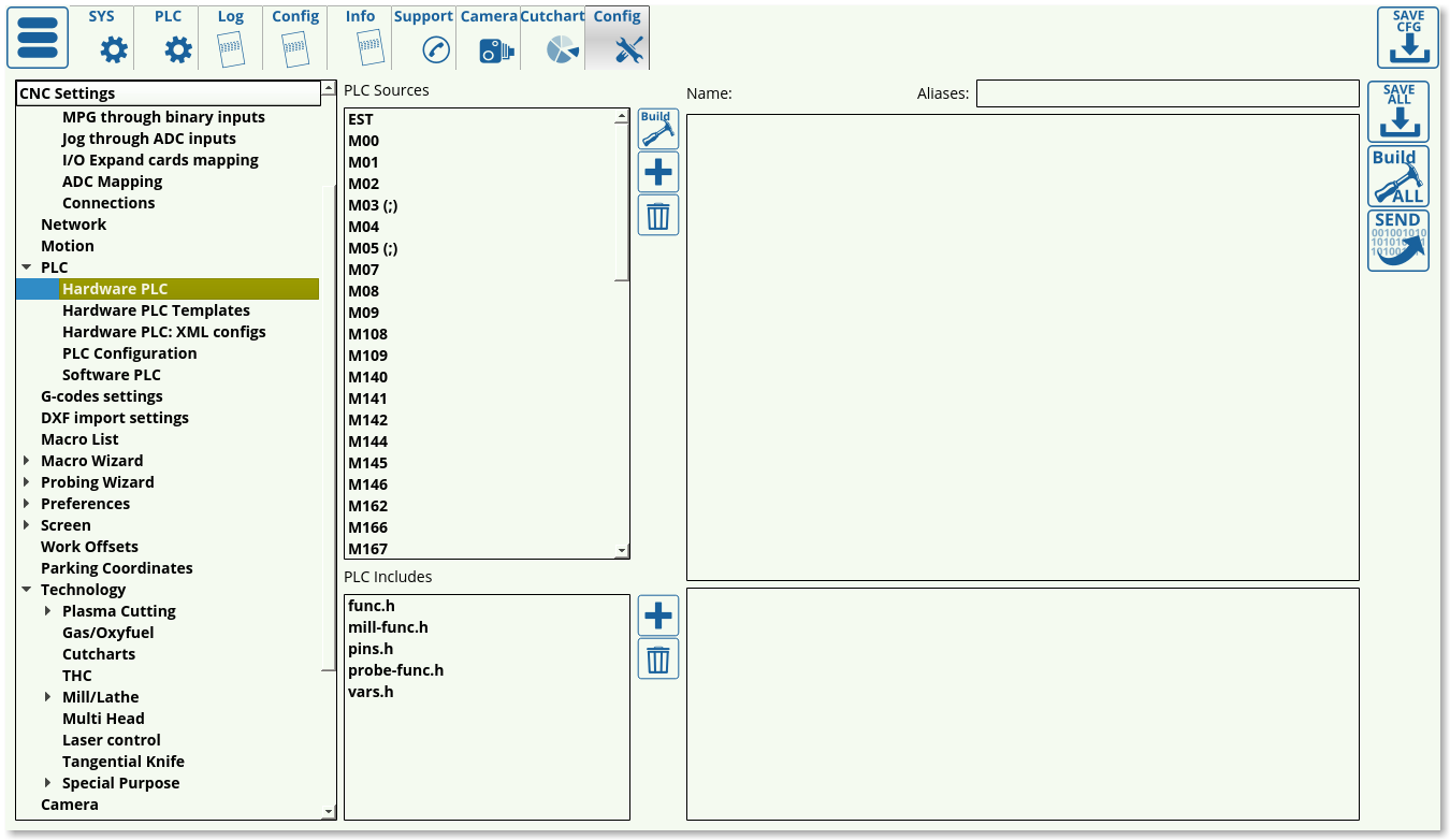 This list presents the available hardware PLC macros, with the ability to add, delete and edit the individual macros as required. After editing the hardware PLC, remember to press the Build All, Save All and Send buttons for the changes to take effect.
Hardware PLC Templates
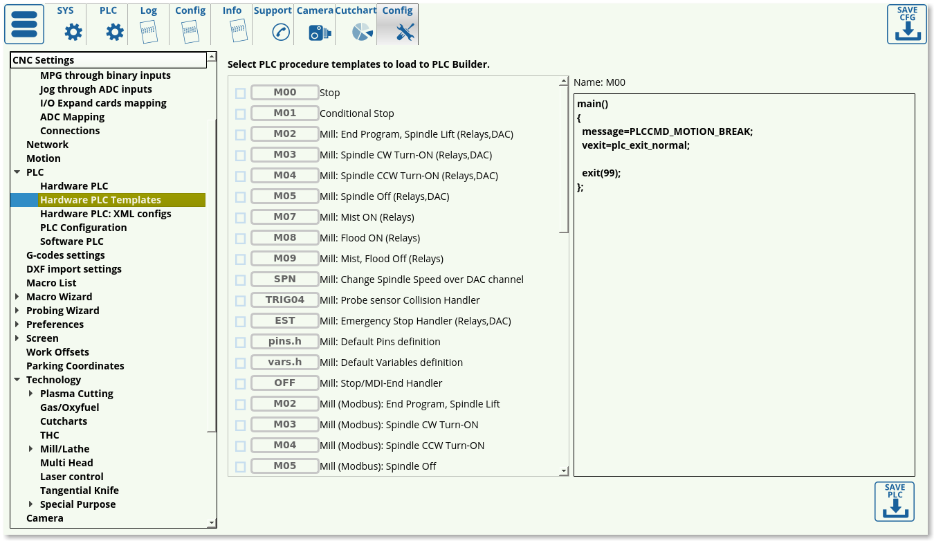 This list presents the available templates that are commonly used in some CNC setups, including macros such as Emergency Stop Handler, the CNC Vision camera macros for finding the registration marks, etc. This page allows the user to load the commonly used macros into the myCNC Hardware PLC list even if the original macros have been changed/removed.
Hardware PLC: XML configs
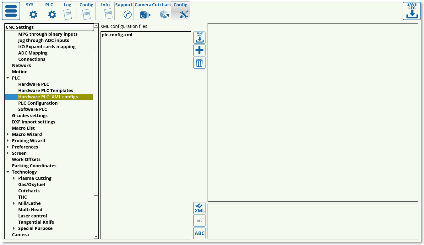 XML configs list currently consists of the plc-config.xml file which serves to connect the macros and the screen elements for these macros by assigning and storing proper variable names. This file should not be edited unless strictly necessary.
PLC Configuration
 The PLC configuration window allows the user to switch to an old-style precompiled ROMFS PLC disk if necessary instead of the more recent Internal PLC Builder setup.
Software PLC
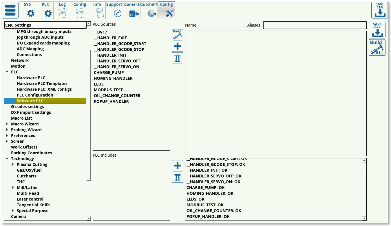 The Software PLC list consists of the PLC macros such as the Oil Change Counter and the Popup Handler which are done on the software side, rather than the hardware side. These Software PLC commands typically consist of items which are less time-critical, but require a continuous timer (like the oil change counter), or items which are loaded once the software is started/existed (HANDLER_INIT and HANDLER_EXIT).
G-codes settings
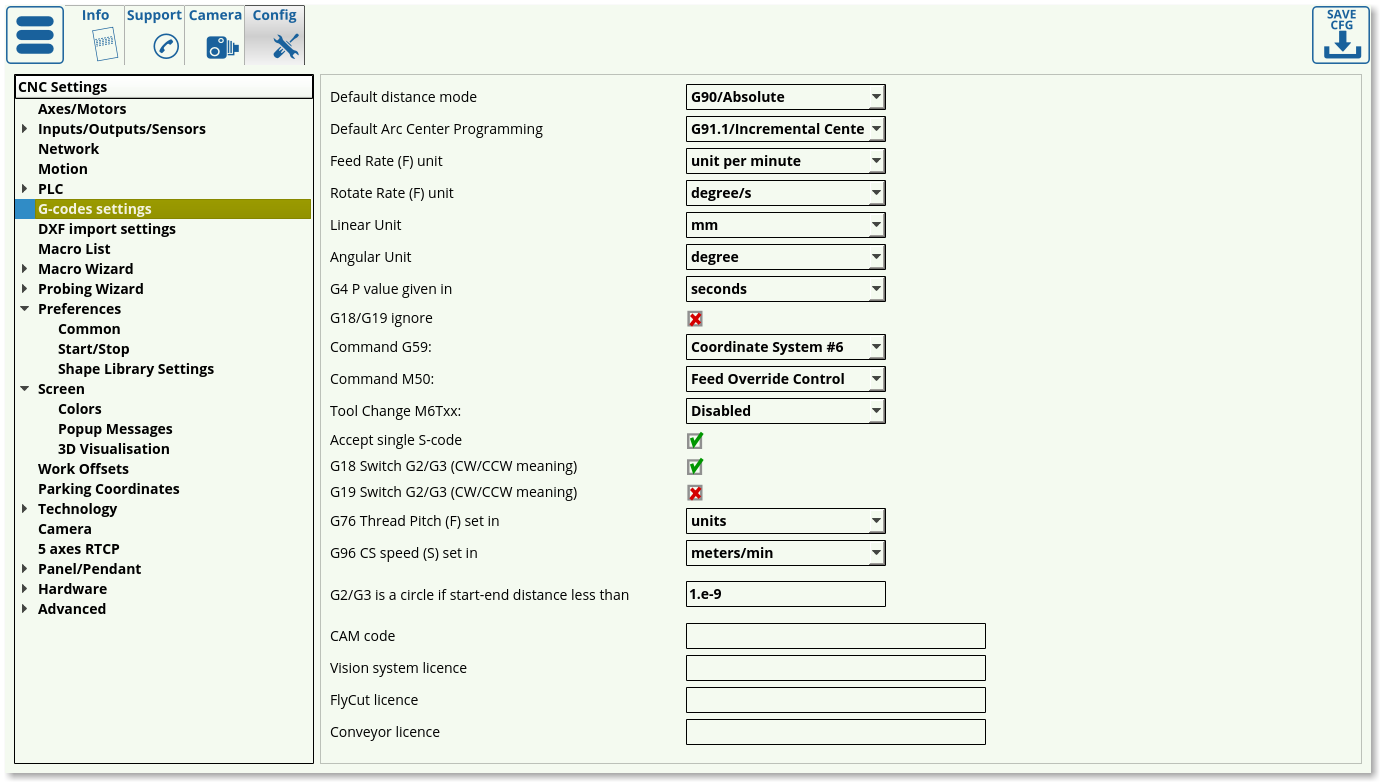
The G-code settings allow the user to fine-tune the preferences for g-code operations.
- Default distance mode can be switched between G90 (absolute) and G91 (incremental) modes to be used as default when loading the program
- Default Arc Center Programming can be G91.1 (incremental center) or G90.1 (absolute center)
- Feed rate units can be switched between units per minute and units per second
- Linear and angular units are set to be in mm/inches and degrees/radians/gradians respectively (usually set to be in mm/degrees)
- G4 P Value is the pause value given to be in seconds/milliseconds
- G18/G19 ignore toggle indicates whether to ignore YZ and ZX planes while drawing and only use the XY plane
- Command G59 is set to switch the coordinate system to Coordinate System #6 by default. However, if Hypertherm systems are used, Command G59 can be switched to comply with the Hypertherm command style.
- Similarly, Command M50 can be assigned to THC OFF, Feed Override Control or Hypertherm style of commands.
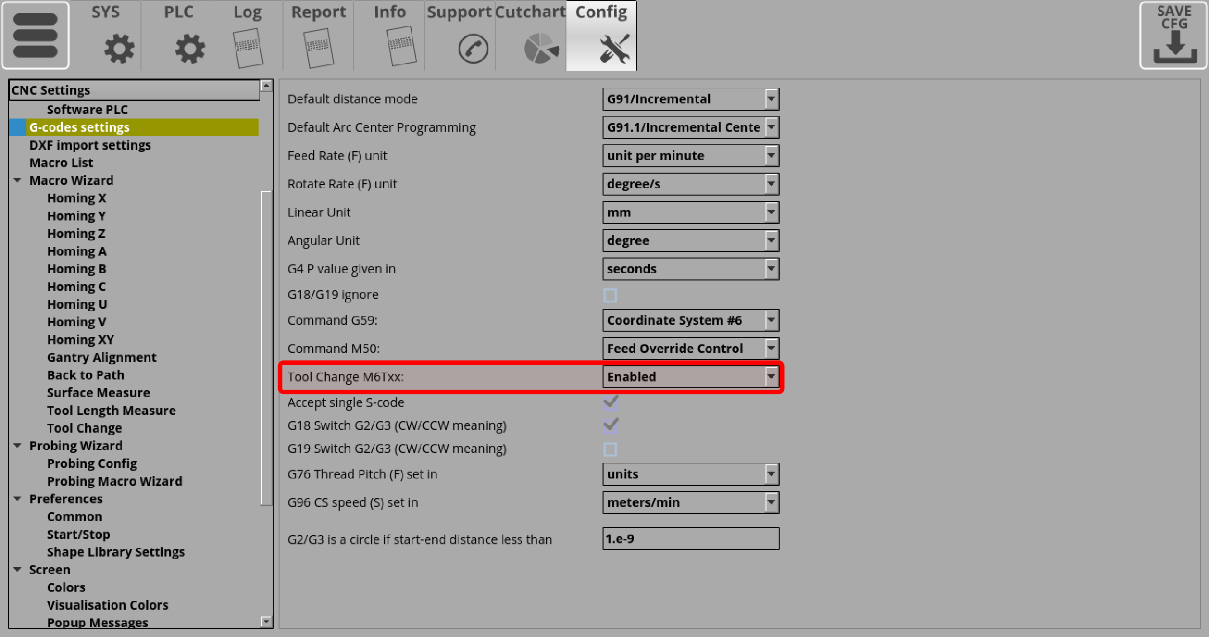
- Tool Change toggles whether the user can set up the tool change from the main screen of myCNC software. Turn ON to enable tool switching.
- NOTE: Tool change commands (M6TXX) will NOT be accepted from the G-code if this setting is disabled.
- Accept single S-code allows the machine to accept single commands for spindle speed changes on the fly. Not applicable to every configuration.
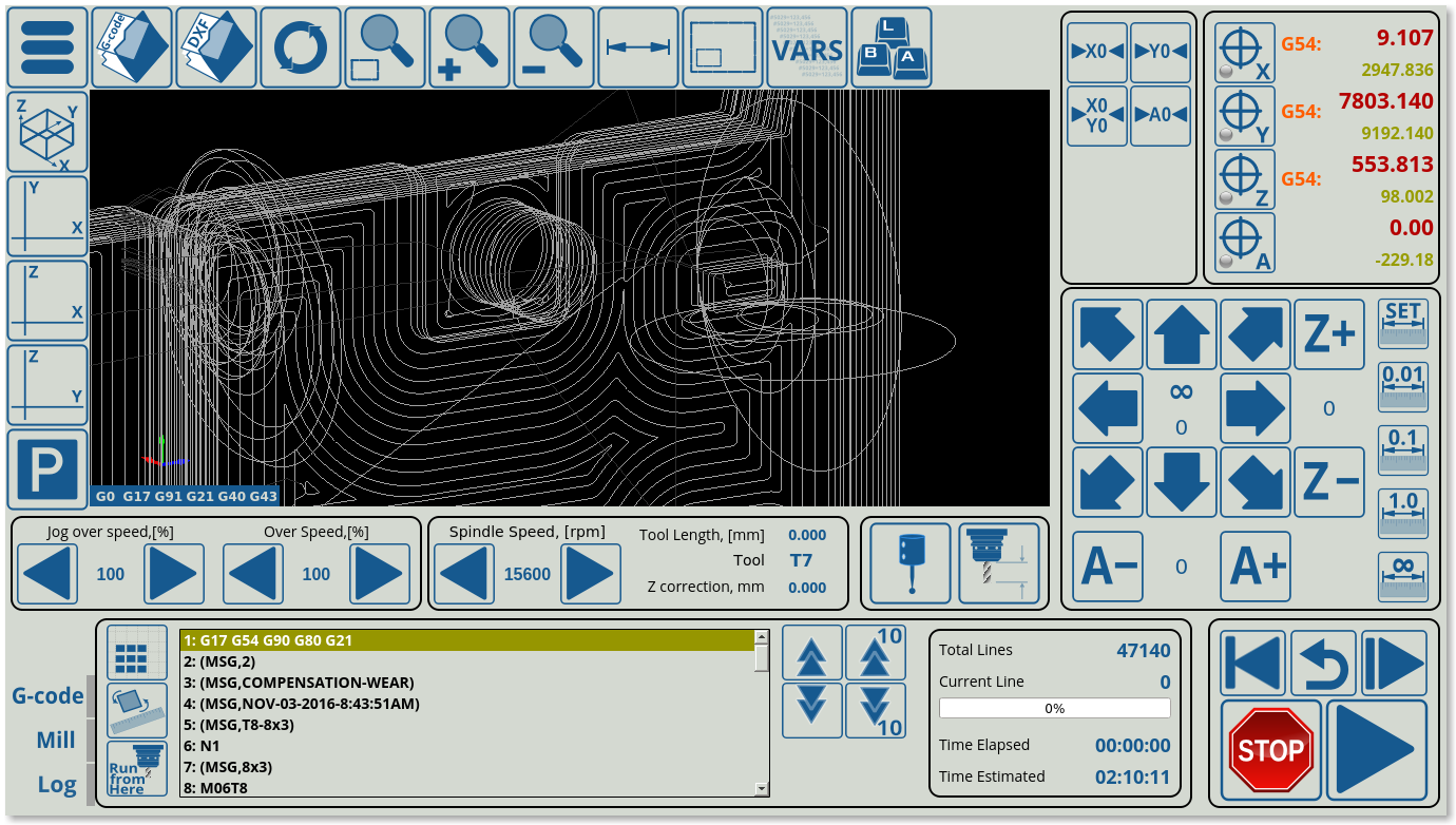
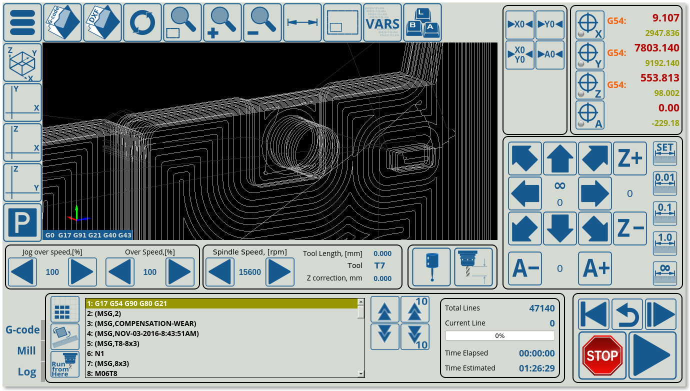
- G18/G19 Switch re-orients the arcs from clockwise to counterclockwise rotation when drawing. Depending on the CAM software used, different configurations of this setting are required.
- For example, in this particular program, G19 Switch is ON, G18 Switch is OFF. As can be seen, the arcs are not drawn correctly:
- Having turned the G19 Switch OFF and the G18 Switch ON, the arcs are now drawn properly:
- G76 Thread Pitch can be specified to be set in the default units (defines as Linear Units earlier) or as mm/inches depending on the operator's needs.
- G96 CS speed is the constant speed setting which can be set to be in meters or feet per minute.
- In certain older CAM software packages, the start/end points of a circle do not coincide correctly, leaving a small gap inbetween the two points which should be directly superimposed. It is possible to disregard very small distance that would be otherwise present between these two points and assume that they are, in fact, the same point using the “G2/G3 is a circle setting”. This distance should be set to be small as to not create false positives of two points being otherwise not connected by an arc.
- CAM code, as well as the Vision system, Flycut and Conveyor licenses are also specified on the G-code page.
DXF import settings
The DXF import settings window looks as follows:
- The window at the top corresponds to the one seen by the user upon importing the DXF file. These technology settings can thus be edited both from this Config window and the DXF import window.
- Below it is the list with all the DXF layer names imported into myCNC. This allows the user to set default tools/priorities to the layer names used in the DXF file if the user so desires. This makes importing a large number of files easier if every layer name has already been standardizes in the illustration software used.
- The DXF Header and DXF footer allow the user to insert macros in the beginning and at the end of the entire DXF file, as opposed to the headers and footers for each particular technology on the Import screen which are only used for one particular tool.
- It is possible to Hide DXF Settings tabs in DXF Import if the user so desires by using the dedicated toggle. This will keep the DXF Settings tabs on this config page, but will remove it on the import screen
- DXF Scale and DXF Offset are direct copies of the settings on the Import screen and can be edited in either location
- Ellipses interpolation can be set to be by Lines or Arcs, depending on the usercase.
- Ellipse segments specify the number of segments into which the ellipses will be split
- DXF toolpath optimization toggle allows the myCNC software to optimize cut time in DXF/HPGL files by choosing the closest next cut as the program is running. This setting is usually left ON, as it allows to create a valid toolpath for a simple Photoshop file etc, however in case that the file you are importing already has a specified toolpath it can be toggled OFF so that the toolpaths do not conflict. See the screenshot below for a comparison of unoptimized versus optimized HPGL import:
- Contour direction is useful on mill/plasma machines which care about the clockwise/counter-clockwise direction with which the tool is cutting the material. It can be set to Original, CW, or CCW.
- Spline segments specifies the number of segments the splines are split into in order to create their linear approximation within the software.
- Each particular technology can be toggled on/off depending on whether the user wants to see each particular tab on the Import screen (for example, only Knife/Plasma/Gas/Engraving, etc).
Macro List
The macro list consists of a list of macro commands (for example, the macro commands related to sensors and homing, etc).
Macro Wizard
The macro wizard allows the user to generate macros for actions such as homing and tool measure. The available macro generating windows are described below.
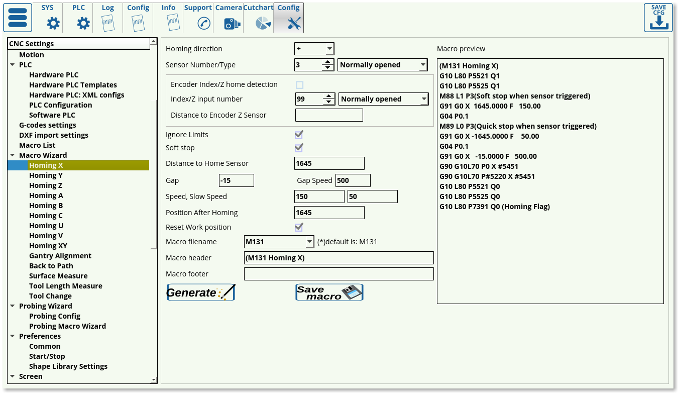
Homing XYZABCUV
Homing settings are available for all the potential axes that are used by the myCNC software (X, Y, Z, A, B, C, U, V), as well as the XY-plane.
In order to set up homing, the following settings are available:
- Homing direction. This is selected depending on where your sensor is located in relation to the working bit of the machine. If the machine will have to move in the negative x, y or z direction to find it, select - (negative). If the machine will have to move in the positive x, y or z direction, select + (positive direction).
- Select your sensor number (depending on how you have connected it) and its type (normally opened or normally closed) which describes the behaviour when the sensor is NOT triggered.
- Choose your Limits behaviour in the Ignore Limits field. Set the check mark to ON if the sensor you are using for homing is the same as the one you are using for your limits (most common case, as coming into contact with this sensor would trigger a limit indication to the machine), and set it to OFF if you are using multiple sensors.
- The Soft Stop setting allows for a gradual stop after the sensor has been passed, allows for less mechanical impact on the machine which would otherwise be present during abrupt stops
- The Distance to Home Sensor has to be set up to be slightly higher than the maximum length that the working piece will have to travel to find the homing sensor
- Using the Gap setting, the user can add a gap between the sensor position and the new software Home position. The Gap Speed will describe the speed with which the machine moves between the sensor and the gap end
- Speed field specifies the speed at which the machine is moving during its initial movement towards the sensor. After the machine triggers the sensor, it starts to move back in order to find the precise spot at which the sensor has been triggered, at the Slow Speed (which allows for more precision).
- Position After Homing field specifies the value assigned to the position after the homing (typically left to be at 0)
- Reset work position toggle specifies whether the user wants to reset the work position or not after the homing has been complete. This is typically left ON.
- Macro filename should be left at its default name unless strictly necessary
- Macro header and macro footer allow the user to input some text, or some other macro, at the beginning and at the end of the main body of the homing macro.
For a full guide on homing, please consult the QuickStart Homing Manual.
Gantry Alignment
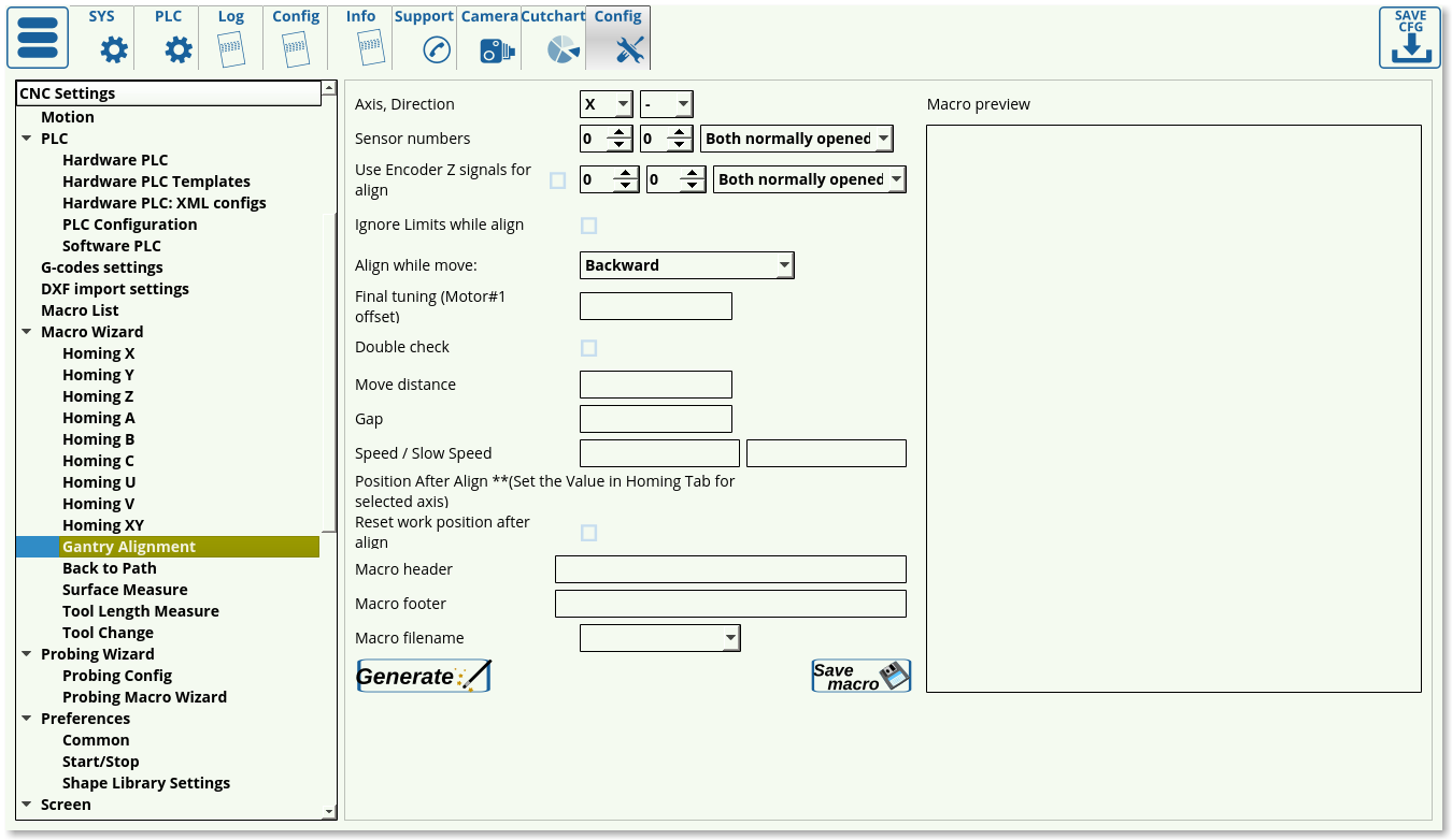
The gantry alignment macro allows the user to generate a macro for dual motor gantry alignment.
Several methods of gantry alignment can be used. By default, the method with two side sensors to move both motors will be set through this config window, however, more methods which can be set up through PLC can be found in the full Gantry Alignment manual.
The following settings are available in the default alignment method:
- Axis: the particular axis for which the gantry alignment macro will be generated.
- Direction, + or -. This is the direction into which the machine will be moving during the alignment procedure (in this case, it will be the negative y direction).
- Sensor numbers which are used for the alignment procedure and whether they are normally opened or closed. This default behaviour should be checked through the Diagnostics window, as it can be inverted in Hardware > Common Hardware Settings.
- Encoder Z signals, if those are used (typically left to be OFF).
- Ignore Limits while aligning flag. Sometimes the sensors used for aligning are the same sensors as would be typically used for a limit signal when the machine reaches its limits. In order to prevent them functioning as the limit sensors (and therefore aborting the entire procedure as they will be triggered) during the gantry alignment process, the check mark can be set to ON.
- Align while move - can be set to be Forward or Backward. The Forward configuration works as follows: One side reaches the sensor, and the motor for that side stops, while the other side's motor continues forward until the opposite sensor is reached, then stops as well. This method is not ideal as the first initial stop is done at a high speed as the machine suddenly comes into contact with the sensor. The other method is to go Backwards, by triggering one sensor, passing that sensor on one side, then reaching the sensor on the other, stopping and moving backwards until both sensors are triggered again. Then the motors move to align the system. This method is preferable as the alignment process is done at a lower speed, however it is not feasible if the sensors are set up right near the edge of the table, preventing the machine from moving past them (in that case, the Forward setting should be used).
- Final tuning allows to set the distance to move the machine if the user knows that the sensors are not set to be perfectly, but one is misaligned by a certain small distance. This small distance should be inputted into the final tuning field.
- Double check - this allows for a greater precision alignment when using the Forward setting, by moving back after hitting both sensors and then forward again at a slower speed. This feature is currently under development, and can be set manually in the generated PLC by adding relevant PLC code for a double check movement at a lower speed.
- Move distance specifies the maximum movement distance that can be travelled during the alignment process (set for safety reasons if the machine never locates the sensors)
- Gap is the distance that the machine will move out from the sensors after the alignment
- Speed specifies the motion speed towards the sensors (slower is typically better as it allows for higher precision)
- Slow speed is used on the Backwards method (not used on the Forwards method), and is employed as the machine is moving backwards after having initially triggered both sensors. This speed is set to be slower to allow for greater precision as the sensors are triggered again (released).
- Reset work position after align allows the work position to be set to the alignment position after the procedure has been completed.
- Macro filename is set to M132 by default.
Back to Path
This window generates the back-to-path macro which will later be used to go back to the working path when the machine is stopped/started back up again. Typically, the back to path settings are used by plasma machines, while the Start/Stop On Start are used by mill machines, despite the similarities for the both processes.
The following settings are available:
- Lift: Lift can be chosen between Lift to Top, which goes as high as the machine allows, incremental lift to raise the working tool by a certain vertical distance from the working position, absolute lift to raise the tool to a set height, or no lift to leave it as-is. The absolute/incremental values can be edited in the field below if their respective check marks are flagged.
- Back to Path moves specify the particular movement order to be used. It is possible to move back in two moves, only moving in the select axes for each particular one. For example, the user can set the first move to bring back the XY axes, while the second move will bring the working tool down in the z-axis. Typically, on plasma machines, only the XY-axes are selected as the nozzle will have to be brought down to generate the initial spark anyway and is done separately.
- Move down gap specifies the gap that will be left after the tool has been brought back down. If the value is left blank, the tool will be brought down all the way to the initial stopping position.
- Move down speed specifies, if so required, a speed with which the working tool will move back to the working path.
- Header/footer allow to insert other PLC commands before/after the main body of the back-to-path macro. Multiple macro commands should be separated with semicolons.
- Macro filename is typically left to be M990.
Surface Measure
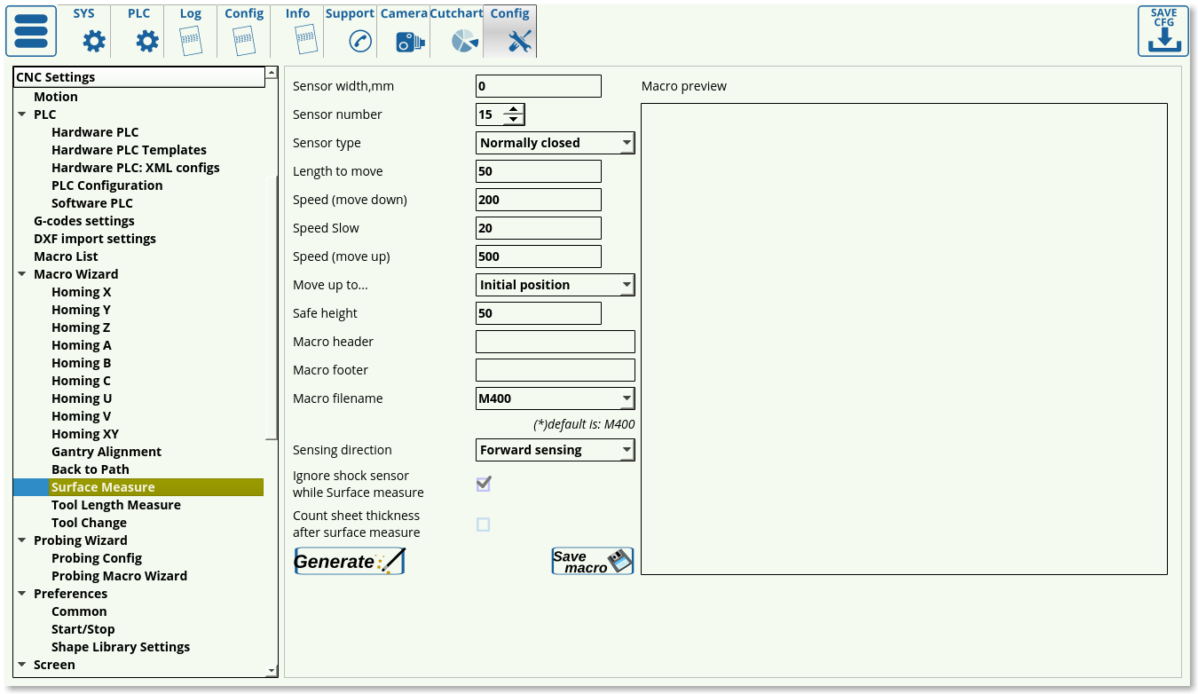
The surface measure config window allows the user to generate a macro which will be then used to check the zero value for the z axis. This is useful when using a sensor on top of a sheet(s) of working material.
The following settings are available for macro generation:
- Sensor width. The sensor width/height is specified here.
- Sensor number - specifies the sensor used for the surface measure procedure.
- Sensor type - normally closed or normally open. Check the default behaviour in the Diagnostics window. The default behaviour can be inverted in Hardware > Common Hardware Settings.
- Length to move - specifies the maximum distance the machine will move (usually done for safety reasons), should be set to be equal or slightly larger than the distance from the top of the machine to the sensor.
- Speed (move down) - specifies the speed with which the machine is initially coming down until it touches the sensor
- Speed Slow - the slower speed on the return (used on the Backward sensing direction)
- Speed (move up) - specifies a speed with which the machine will be moving after it is coming up after coming in contact with the sensor. This is typically a higher speed, as precision is not relevant here.
- Move up to specifies the position to move after the procedure has been complete. This can be the initial position, the safe height position (absolute for actual height value, incremental for height value relative to the sensor), or top position which makes the machine move as far up as it is allowed to.
- Safe height specifies the height at which the tool will not come into contact with any obstacles as it is moved around.
- Macro header and macro footer allow the user to add additional PLC commands before or after the main body of the Surface Measure command. Separate multiple commands by a semicolon.
- The macro filename is set to be M400 by default.
- Sensing direction can be set to be forward or backward, similar to the gantry alignment setup. The forward will cause the machine to continue moving until it hits the sensor, and then it will stop. The backward method is more precise, as it will move past the sensor when the sensor is initially triggered, and then will move back with a slower speed recording when the sensor is released (this allows for higher precision). This method is useful with button-type sensors.
- It is possible to ignore shock sensor data if the sensors used for the surface measure are the same as the one used for shock analysis. Set the checkmark to ON to ignore the shock sensor signals that would otherwise conflict with the surface measure sensor data.
- Count sheet thickness setting allows to add the sheet thickness, specified in Global Variable #5496, to the sensor thickness. This effectively zeroes the z-coordinate at the bottom of the working material sheet, rather than at the top, and is left to the user to decide. Typically, as most recent profile releases do not provide a direct way to edit GVar #5496, this setting is usually set to OFF.
The macro generated during the surface measure setup includes the M89 command which will check if the sensor has been triggered and will then subsequently lift the probing tool up. However, this macro will not trigger if the sensor has already been pressed before running the command (for example, if the operator has set the probe too low and the sensor was already pressed, the spindle will just keep moving downwards resulting in a broken tool). In order to prevent this, the M286 macro has been added in the more recent software versions. The macro checks whether the sensor is triggered before starting to bring down the probe tool, and if the sensor has indeed been triggered already, lifts the tool up in increments of 1 mm. This continues until the tool is no longer touching the sensor, after which the surface measure procedure continues as normal. The M286 macro is generated automatically and should not be edited unless necessary.
Tool Length Measure
Tool length measure macro allows the user to record the precise tool length.
The following settings are available:
- V2 allows for a double-contact (double tap) procedure.
- Fake procedure allows to forego the actual measurement if the user does not have a tool length measuring sensor. This fake procedure effectively allows the user to measure the tool length manually, bringing the machine to an approximate distance that is roughly equal to the tool length. The macro generated will move the machine at a very low speed, and the sensor should be typically set to Normally Closed in order to immediately stop the procedure (the macro will move the machine a very small distance, until the Normally Closed sensor indicates to the machine that the process should be aborted, then the manually set distance will be used as the tool length).
- Speed XY to specify the speed in the xy-axes
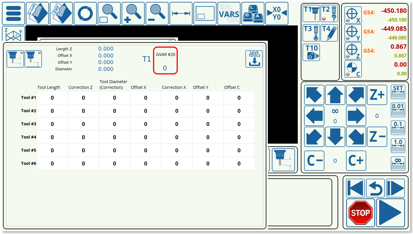
- Speed Z to specify the initial speed with which the machine moves downwards. This is used if the Fast Lowering setting is set for a certain distance in the Tool Specifications window from the main screen of the myCNC software (parameter #20).
- Slow speed is specified for the downwards speed when the Fast Lowering setting is OFF or over (when the fast lowering distance has already been cleared).
- The axes for which the tool comes back to initial position can be specified (for example, only the z-axis height can be used to bring the sensor back up, but there might be no need to move it to the same xy-position, etc).
- Tool length sensor position on the table is noted in machine coordinates (z is typically a negative value).
- The sensor number and type should be set to the sensor port and normally opened/closed.
- Fast Lowering allows to move the machine down faster during the initial stage before it comes into contact with the tool length sensor. Useful for machines with a large z-axis distance as it allows to speed up the process considerably if the tool is brought down for the entire height of the machine.
- The macro header and macro footer allow to input additional commands before/after the main body of the current macro.
- The macro filename is set to M421 by default.
Tool Change
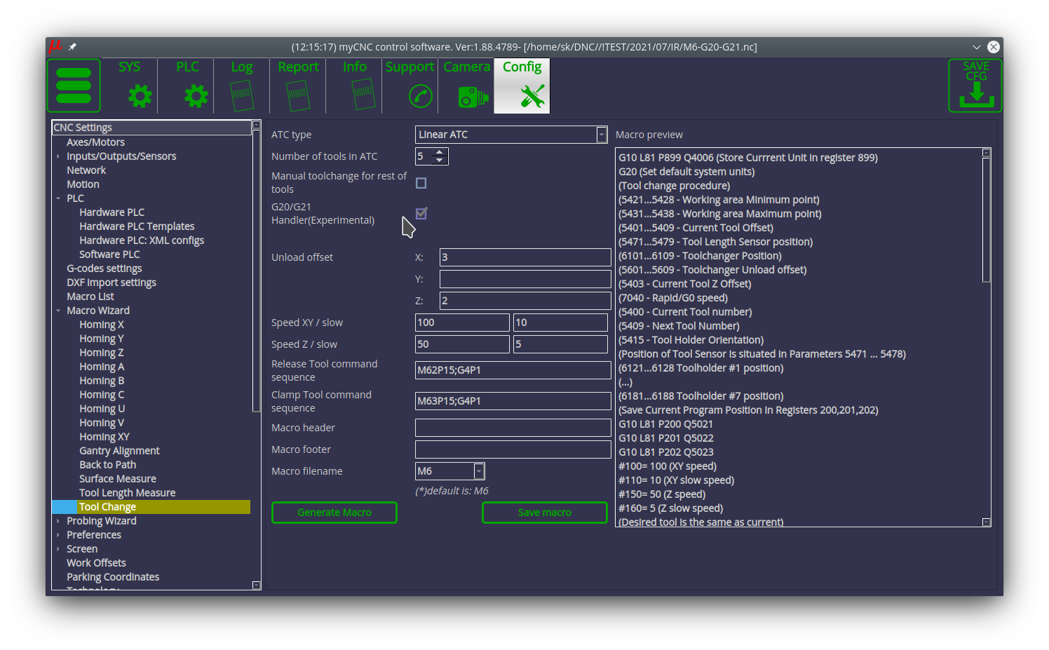
The tool change config window allows the users to set up a macro for a tool change procedure.
The following settings are available:
- ATC (automatic tool changer) type. The automatic tool changer type can be set to be Linear, Rotary (DC motor) or Rotary (Stepper/Servo motor).
- Number of tools in the ATC
- Manual tool change for the rest of the tools specifies if there will be manual tool changes for tools outside the specified range. This way, more tools can be added to the program G-code which will require outside confirmation after change (for example, tool #10 can be specified in the G-code while only 5 tools have been inputted in the field above). Both loading and unloading unknown tools is supported for the manual tool change, and will require external confirmation that the manual tool change process has been completed properly.
- G20/G21 Handler allows myCNC to store the units (mm or inches) that the G-code control program is using at the moment that the tool change macro is launched. After the tool change macro is initiated, it will then use the default dimensions selected for the user profile (for example, if inches are selected in G-codes settings, then all dimensions for the tool change will be in inches). At the end of the tool change macro, the current G20/G21 value is then restored.
- Unload offsets for the X, Y and Z axes specify the particular positions for the load/unload offsets. It is typically set to be some z-axis distance for round tools (as the tool changer will come to clamp them from above, coming directly downwards), and some x/y and z distance for a fork-like setup so that the ATC can move in properly and grab the tool. The movement sequence is reversed for loading/unloading (moving horizontally/vertically will be flipped to allow to both clamp and release the tools depending on the movement sequence).
- Slow speeds for the XY and Z axes are used while loading/unloading the tools after beginning to travel from the offsets.
- Release tool command sequence allows to input some macro for the release sequence after the ATC has been set in place using the offsets
- Clamp tool command sequence allows to input some clamp macro after the ATC has been set in place. These depend on the particular setups and actions needed to clamp/release the tool, and vary from user to user.
- Macro header and macro footer add command macros (as well as text/headings as needed) before and after the main body of the Tool Change macro.
- Macro filename which is usually set to be M6.
Probing Wizard
The probing wizard deals with the probe setup process. To learn more about the probe setup, please consult the QuickStart Setting up the probe tool manual.
Probing Config
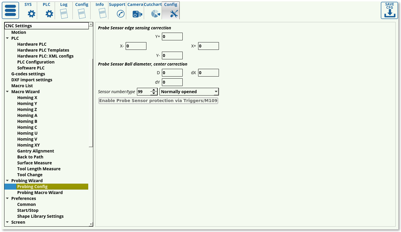
The probing config outlines the following settings:
- Edge correction for positive and negative X and Y directions. This allows for software-side fine tuning if the sensor ball or the sensor rod are misaligned (this is determined experimentally).
- Ball diameter and center correction for correcting a difference between a perfect ball center and the actual imperfect physical sensor (if the ball is not perfectly round and is rather of a slightly oval shape). The values for the correction are typically found experimentally by measuring the sensor ball with high-precision instruments.
- Sensor number and type. This designates the particular port used for the probe sensor, as well as its behaviour when not being in contact with any surface. This default behaviour can be checked in the Diagnostics window, and inverted in the Hardware > Common Hardware Settings window if needed. Pressing Enable Probe sensor protection button after setting the particular port desired will automatically mirror these settings in the Inputs/Outputs/Sensors > Triggers/Timers window.
Probing Macro Wizard
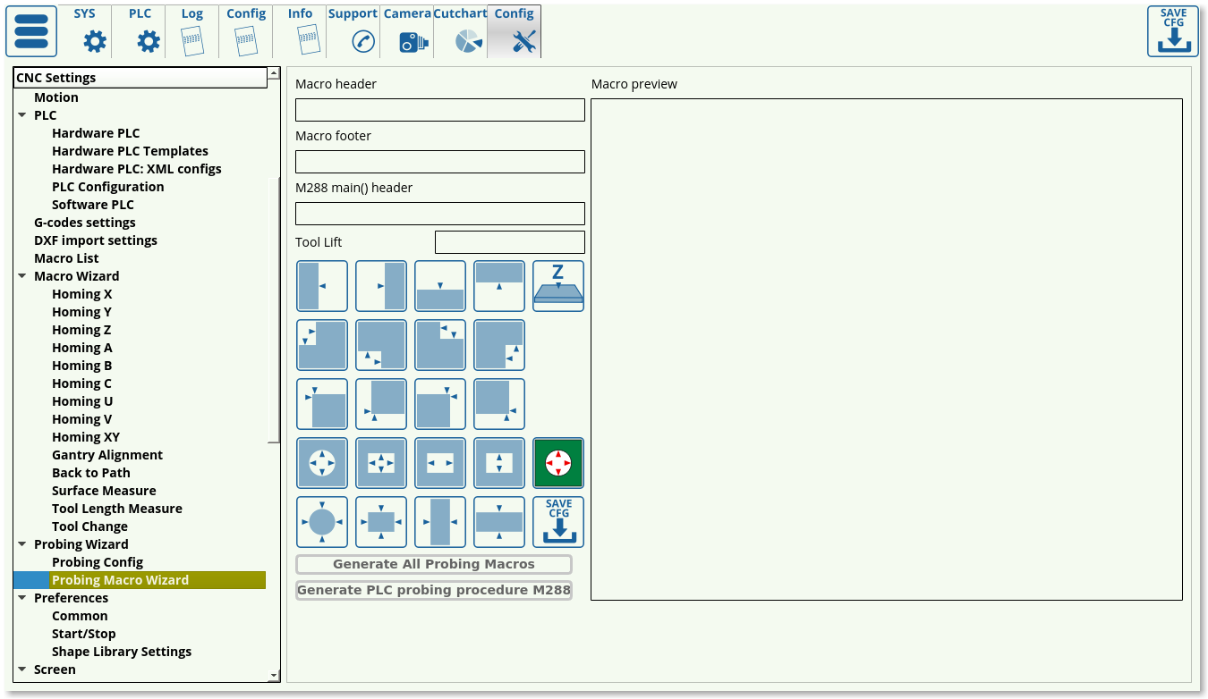
The probing macro wizard allows the user to generate the relevant probing macro for each particular shape and setup.
This wizard involves the macro header, the macro footer, the main() header for the automatically generated M288 macro, the necessary tool lift to safely move the probe over to the required location, and the available shapes for each of which a different macro can be generated (the macro names can be seen in the top line of each respective shape macro). These shapes allow to load in a macro preset for the particular case, and to easily edit the probing macros.
The save config button located in this window will save each individual macro that has been selected.
After clicking the Generate All Probing Macros and the Generate PLC probing procedure M288, the necessary popup windows for the probe sensor will also be generated automatically (popups 20, 21 and 22).
More information on using the probe can be found in the QuickStart Setting up the probe tool manual.
Preferences
Common
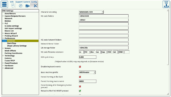
- Character Encoding - myCNC software uses Unicode Text encoding system. If input G-code files contain symbols encoded in other Encoding system, this system should be set in Character Encoding. combobox allows to show local symbols correctly in the myCNC software
- NC code folders - In File Open Dialog and DXF Import Dialog, the myCNC software will search for nc-files in the folders provided in this field. For example, if the NC code folders are set as “~/DNC” and “/media”, then only these folders will be available to open G-code or DXF files through their respective windows. The following standard folders are used on Linux (Ubuntu MATE) installations:
~/DNC/
~/Desktop/G-codes/
- The
~symbol allows you to not write out the whole /home/USERNAME/DNC line, however the full filepath can also be used.
- The following standard folders are used on Windows installations:
C:\DNC
C:\DNC\LIBS
- NC code network folders specify the network folders that the myCNC software will access to look for nc-files. The folder that myCNC will access will also be mirrored (downloaded) to one specified in the next field, Network Mirror Folder, to prevent issues in case of a poor network connection.
- Network mirror folder - when downloading files over the network, download failures are possible, therefore, in myCNC, files from network folders are first copied to the local disk when you try to open the control program, that way the download will be loaded into the application from the local disk. Then, a network failure or simply shutting down a networked computer while a multi-hour file is running will not result in a failure, since the file has already been copied to the local disk. There are settings for this - “NC code network folder” effectively tells the system that this is not a local drive and “Network Mirror Folder” specifies a folder on the local disk where files from the network will be copied. If the system does not have a “mirror” folder specified, then the myCNC application will not work correctly for network access.
- Lib storage folder specifies the folder in which the library parts are stored on the computer. This should not be changed unless strictly necessary, as some libraries in the more recent software versions have the lib folder hard-coded.
- NC code filename extensions lists the possible extensions that the software will allow the user to open. If an extension is not on the list, it can be added provided it can be read by the myCNC software.
- G04 cycle time marks the internal controller setting for time marking in order to properly synchronize the controller and the computer. It should be set to 0.004 by default, 0.008 is another setting that is valid on some controllers.
- The Disable keyboard Events setting allows to completely disable keyboard inputs, leaving only the touchscreen for the user to operate.
- The basic machine profile can be specified to be Mill/Router, Lathe, Cutting Table, or 3D Cutting Table, depending on the user's needs.
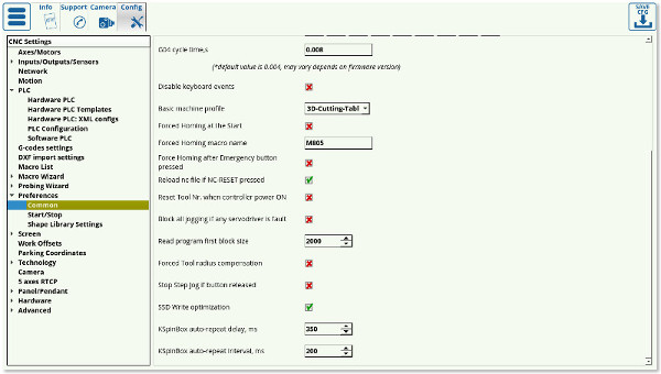
- The Forced Homing at Start and the Forced Emergency Homing settings are used ONLY in older versions of the software and will be deprecated in the upcoming myCNC software versions. The functions of these settings have been replaced by the HOMING_HANDLER from Software PLC and should not be used on any recent software versions.
- Reload nc-file if NC-RESET pressed toggles whether the full file is reloaded upon pressing the Return to Top button on the main software screen. The toggle is left ON by default.
- Reset tool number setting allows the user to reset the tool number after the controller has been turned off and on again. This is an experimental feature for only certain setups, and is not recommended by default.
- Block all jogging if any servodriver is faulty allows the machine to stop all movement if any of the motors indicates issues. Not recommended by default, since the user might still need to lift the part up using the z-axis motor even if both the x- and the y-axes motors fail while this setting would freeze all jogging regardless of which motor has reported issues.
- Read program first block size sets the size of the block of code that the computer will read at a time. This setting is not edited on most recent machines, and is kept at around 2000. If using an older host computer, this block size can be reduced.
- Forced tool radius compensation - by default, the computer checks the first block of code with the size specified in the field above, and then tries to locate tool radius compensation commands in that first block of code. If it has not located tool radius compensation, the computer will assume that the entire program is free of tool radius compensation, and will proceed without account for it, saving time. If, however, the user is aware that there is tool compensation at some point in the program that is further than the first code block size, the toggle for Forced Tool Radius Compensation can be turned ON. This will force the machine to account for tool radius compensation, however this will also significantly slow down the cutting process.
- Stop Step Jog if button released toggles the behaviour of the buttons which control the step jog. With the toggle OFF, every press will make the machine move by a certain set distance, while with the toggle ON, the user will have to keep pressing the button until the movement has completed for additional safety.
- SSD Write Optimization toggle controls the program utilizing cache instead of writing to disk. This is turned ON by default.
- KSpingBox settings specify the behaviour of the control buttons on the main software screen (such as the overspeed buttons). These settings are usually left to be at their default values unless changes are necessary.
Start/Stop
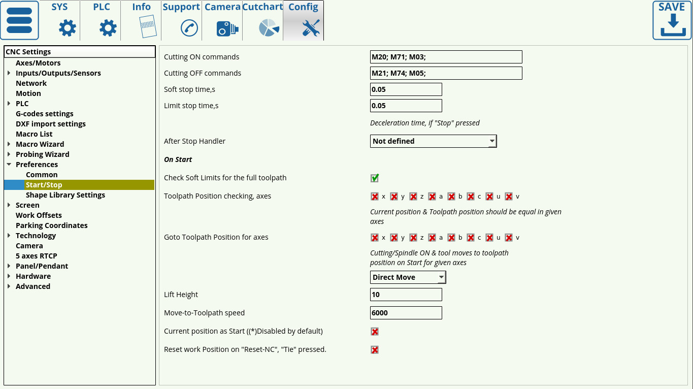
The Start/Stop settings specify the behaviour of the machine as the start/stop commands are sent to it.
Among other settings, this window allows to edit the back-to-path behaviour on mill machines through the On Start section.
Consult the QuickStart Start/Stop Setup for a full overview of the available features.
NOTE: Some plasma features (such as the tie toolpath to position button) require to have axes selected in the Toolpath Position checking field. Without the check marks for the axes that you would like the machine to check for, no action will be performed (on plasma machine, X and Y axes are recommended to be selected).
Shape Library Settings
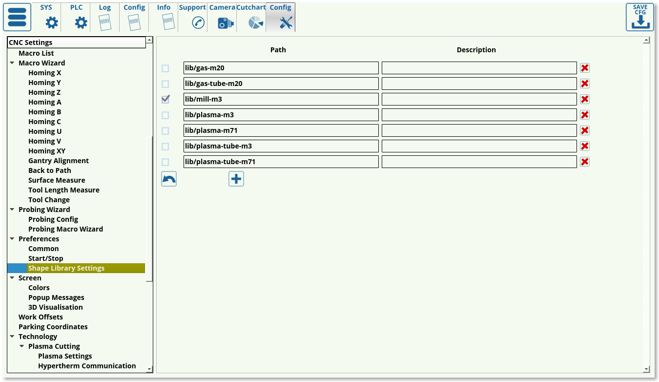
The shape library settings allow the user to load in different modules designed for different machines and applications.
In order to prevent clutter in the Shape Library, only the necessary shapes can be selected to be displayed. The following subcategories are available, with the particular G-code start commands that are used for each particular setup listed in the title of each category:
- Gas-M20
- Gas-tube-M20
- Mill-M3
- Plasma-M3
- Plasma-M71
- Plasma-tube-M3
- Plasma-tube-M71
The user can select/deselect the necessary packages.
NOTE: The shape library packages must be located in the lib folder. Trying to access the shape library from other folders, even with the correct filepath, can lead to issues with the Shape Library.
Screen
The screen settings allow the user to edit the appearance of myCNC software.
The following settings can be edited:
- Language can be switched by inputting the corresponding two-letter acronym (en for English, ru for Russian, es for Spanish, pl for Polish). More languages will be added to myCNC software in the near future. If a native speaker desires to aid the localization process, the myCNC team will provide the user with the myCNC translation .xls file (more information is available in the Language Localization manual).
- Theme can be switched by specifying the path to the folder containing all the images for a given theme. This folder should be located in opt/myCNC/art/buttons-no-theme.
- Buttons skin field specifies the folder from which the icon frames are taken. This folder should be located in myCNC/art/buttons-no-theme/THEMENAME and the field is using the rect folder by default. Read more about themes and button skins here
- Style can be specified via a [name].style (x.style by default) file which can be found in .config/myCNC/profiles/PROFILENAME. Note that the stylesheet should only be changed when strictly necessary as it allows to edit the entire myCNC layout throughout the application. More information about the styling used in the x.style sheet can be found at the Qt Style Sheet Wiki
- Full screen toggle to make the myCNC application full screen
- Maximize screen toggle to make the application take up the full screen, with the window buttons (close/minimize) still present
- Fixed screen size to give the window a pre-set size. Note: this does not work with the maximize/fullscreen modes.
- Hide Left Tabbar to hide the older version of the navigation window (ON by default in all the newer 1366 profile versions)
- Hide cursor allows the users with a touchscreen setup to hide the window cursor
- 2D visualization: AutoScroll is useful for large plasma machine configurations, where the user wants to take a closer look at the visualization of the cut with the window automatically following the cutting indicator. OFF by default.
- 2D visualization: Unfold A axis is used when pipe cutting files need to be unfolded (usually due to the specifics of the CAM program used when creating the original file). OFF by default.
- 2D visualization: Rotate rotates the file visualization 90 degrees off its original layout. OFF by default.
- Linear axes can be displayed in mm or inches. This is done for visualization purposes, and does not impact the actual measurements of the original file.
- Rotary axes can be displayed in degrees, radians or gradians. This is done for visualization purposes, and does not impact the actual measurements of the original file.
- MDI widget configuration allows the user to edit the on-screen input field/keyboard. The following settings can be edited.
- Width and length of the on-screen widget.
- Virtual keyboard can be enabled or disabled
- The closing behaviour can be edited to close on Enter press
- Widget position can either be chosen to be in a custom location, or centered.
- Pendant widget configuration allows the user to edit the pendant widget (currently present on the 1280 profile series). The following settings are available:
- Pendant view
- Widget size, in px
- Buttons present in the widget (axes, jog buttons, +/- buttons, pendant step buttons)
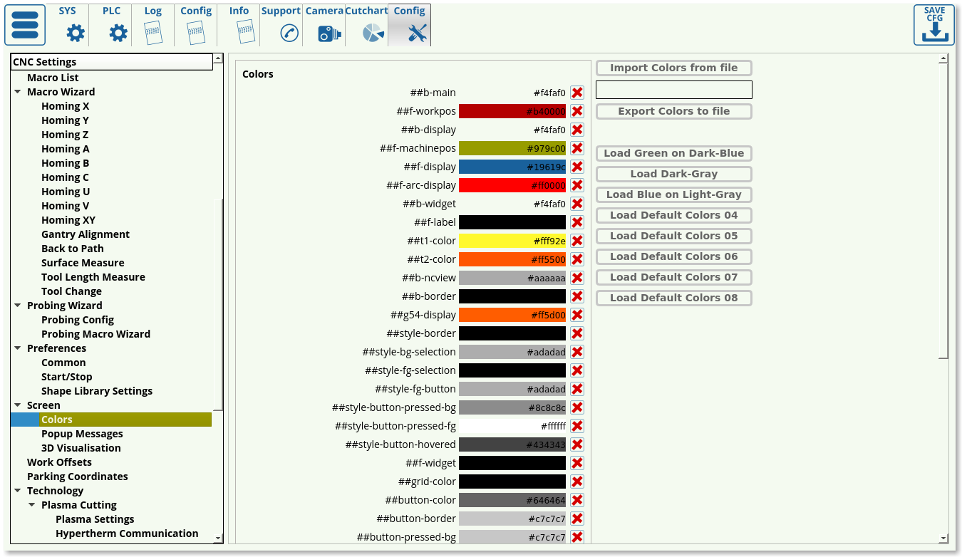
Colors
The colours config window allows the user to customize the visuals of the myCNC application. In this window, presets such as the dark grey and the dark blue themes can be preloaded, or customized completely from the ground up. When the user is satisfied with their particular theme, they can export it by using the Export Colors to File button.
The colors can be assigned via an HTML code (for example, #00ff00 for bright green). The color can be either selected via the built-in color picker, or via an HTML picker online such as this one.
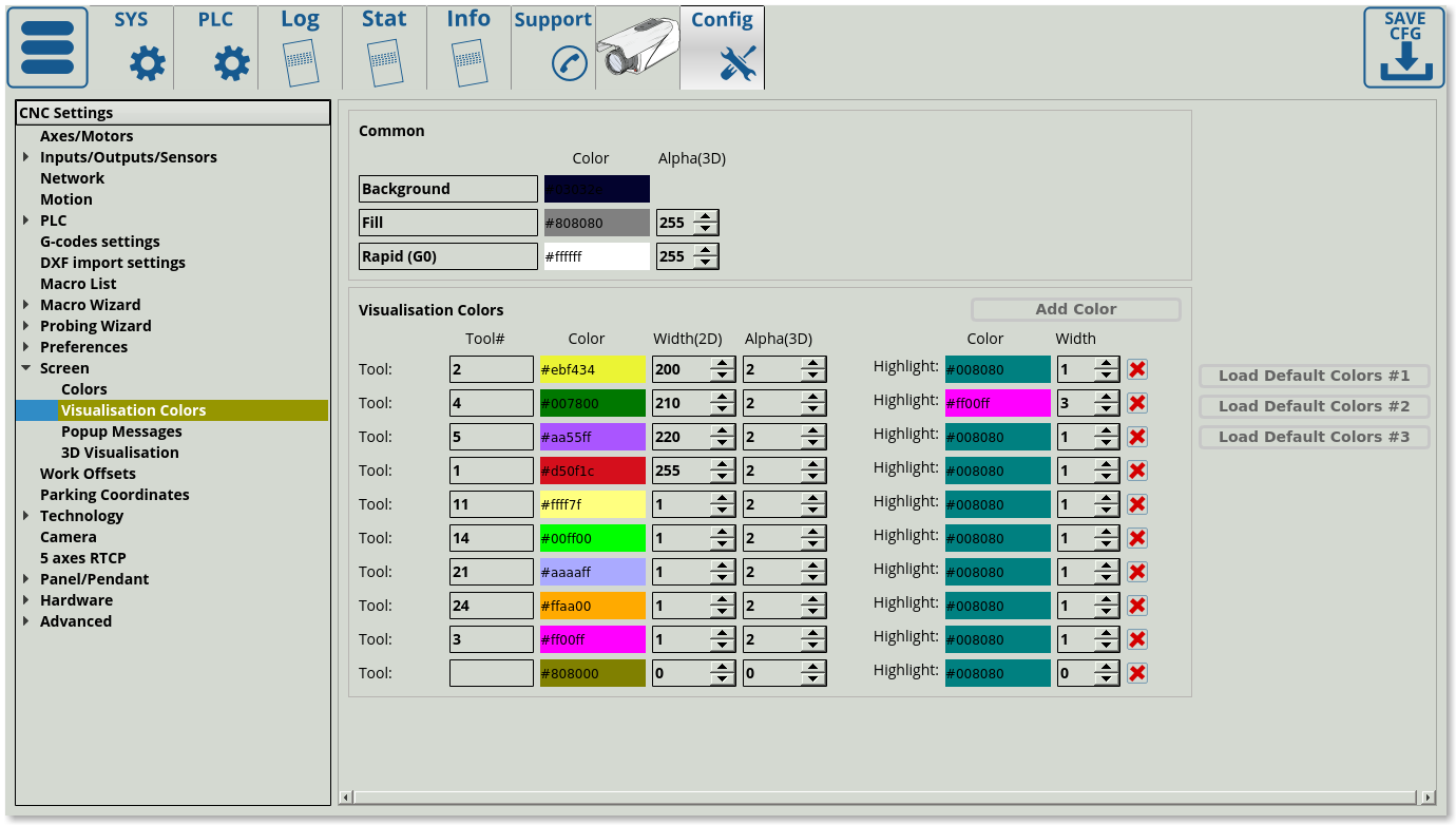
Visualisation Colors
The visualisation color settings allow the user to specify the colors that will be used in the program visualization for each of the tools in the program code.
This allows the user to set each tool to an easily distinguishable color:
- Tool Number specifies the particular tool assigned to the color
- Width specifies the 2D width line, alpha specifies the 3D opacity (0 for transparent, 255 for opaque).
- Highlights are currently supported for 2D profiles only (such as plasma), and allow the user to highlight a certain tool path by clicking upon it.
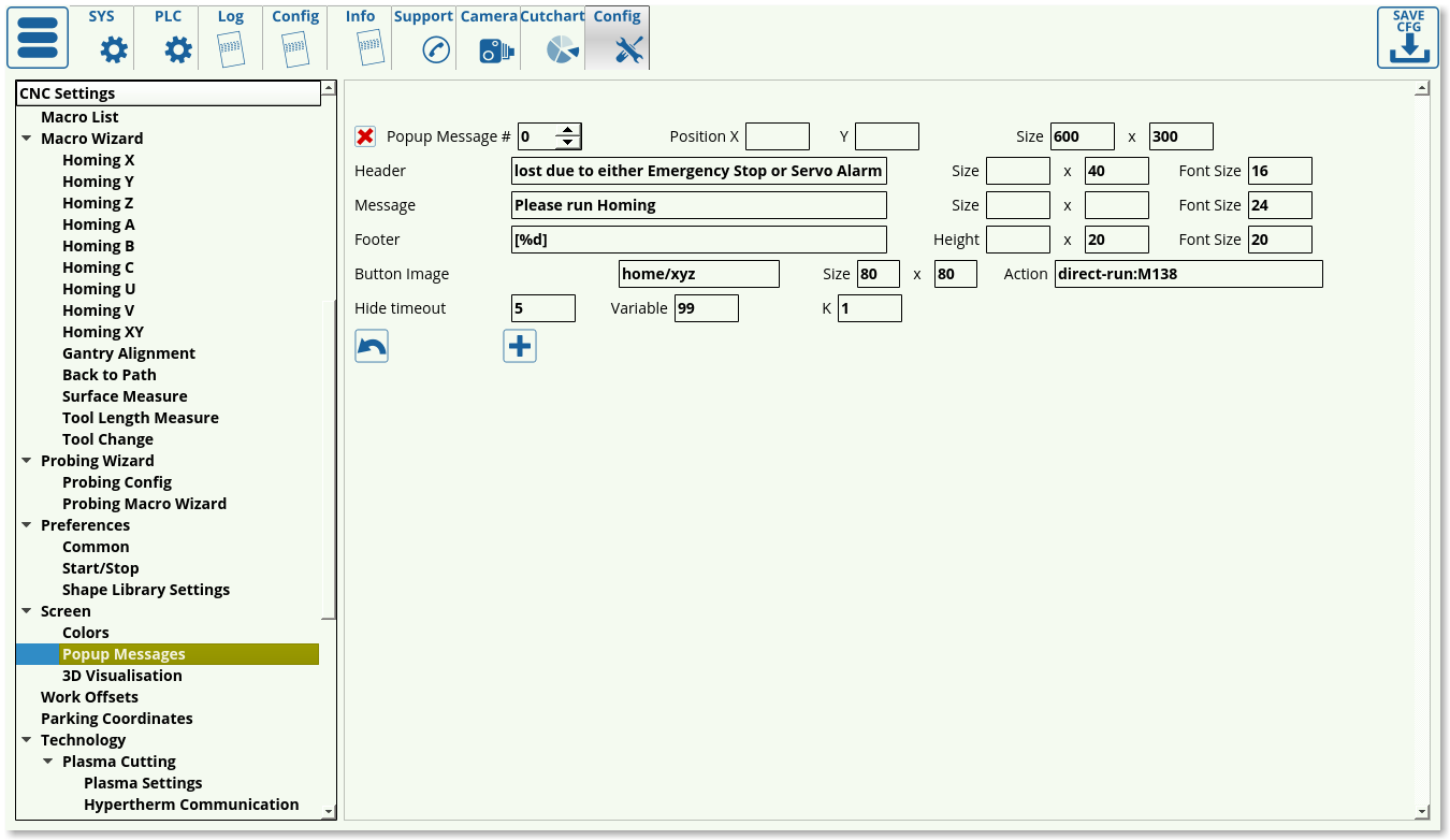
Popup Messages
This section deals with the popup messages that the myCNC software presents to the user when an event requiring attention occurs.
The following settings are available:
- Popup Message Number
- Position (X&Y) on the screen
- Size of the popup window (in pixels)
- Header (title) of the popup message
- Header size and font size
- Message (body) of the popup window which allows to present additional information to the user
- Message size and font size
- Footer of the popup message
- Footer size and font size
- Button image (specify the file location)
- Button size
- Button action to run a specific macro when the button is clicked
- Timeout to hide the popup window (in seconds)
- Variable number to display (usually in footer, through [%d]) - useful to display a changing variable, like time in seconds, etc.
- Coefficient K to multiply the variable by. Useful to convert tiny incremental changes (such as fractions of a second) or large rapidly changing numbers into numbers that can be easily read by the user.
For an example on popup messages, please consult the How to add mandatory Homing after Emergency Button and-or Servo ready alarm manual.
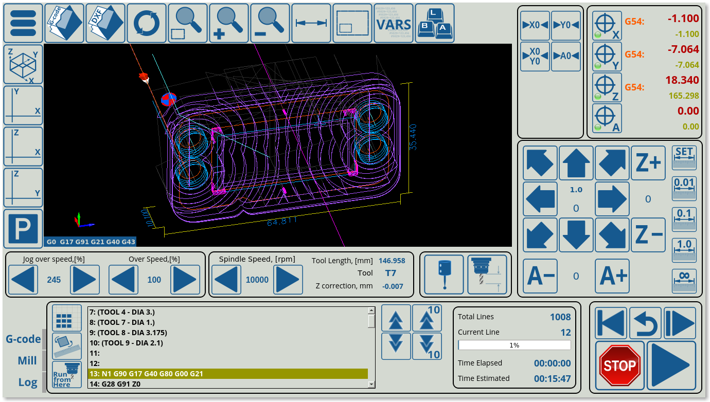
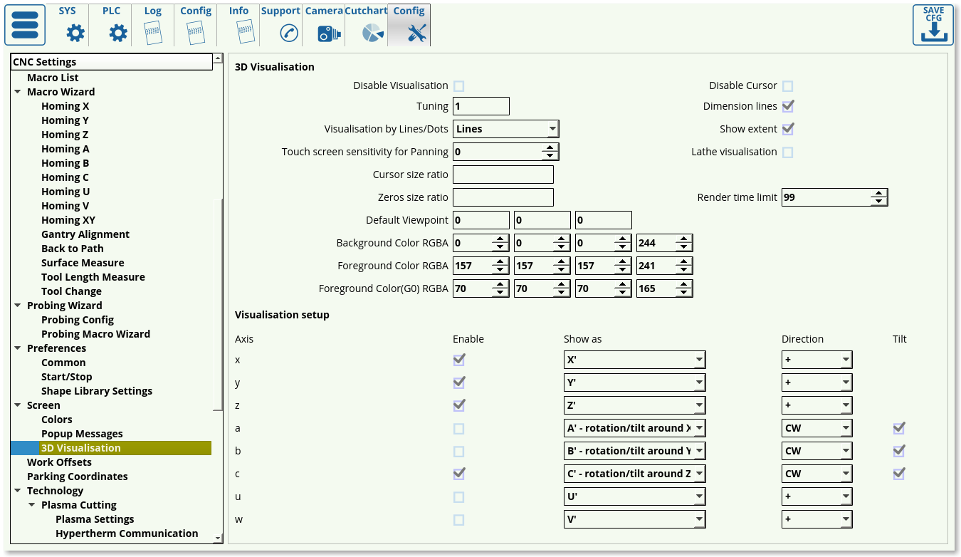
3D Visualization
3D Visualization deals with the visualization window on the main screen of the myCNC program. It allows to visualize the incoming G-code commands to easily present to the user the current layout and work tool position.
The following settings are available:
- Disable Visualization toggle
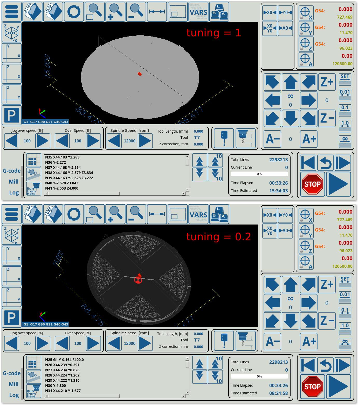
- Tuning allows for fine visualization adjustments in large files. When a program file contains a large number of overlapping lines, the fine detail can be drowned out, so setting the tuning parameter lower than 1 will reduce the line brightness, allowing for a clearer picture. Below is an example of a large program (2 million lines) and its visualization at tuning 1 and tuning 0.2. As can be seen, the tuning 0.2 is a lot clearer on large programs, while on smaller programs the same setting would make it hard to see the individual lines:
- Visualization by Dots/Lines. Lines are set by default, and dots should not currently be used as it is a test option.
- Touchscreen sensitivity for panning. It is often needed to hold the touchscreen edges in order to pan the image, however while holding the touchscreen the image might jitter, causing the pan to stop. In order to ignore small finger movements, bring the Touchscreen Sensitivity value up.
- Cursor size ratio sets the particular size for the cursor (easier to visualize if the screen is located at a distance from the user)
- Zeros size ratio (sets the zeroes position marker to be smaller/larger)
- Default viewpoint (typically set to be at 0, 0, 0) - can be set at an angle that will be showing the part by default such as 45, 45, 9
- Background Color RGBA
- Foreground Color RGBA
- Foreground Color (G0) RGBA
- Disable Cursor toggle
- Dimension lines toggle turns the overall dimensions lines around the part on/off
- Show extent toggle will show/hide a box around the part which shows the physical limits of the part's extent
- Lathe visualization toggle allows for a visual representation of a lathe part, including the cutting lines and the part itself
- Render time limit. On slower machines, such as TinkerBoard computers, it is often recommended to set a low time limit (2-5 seconds) to not overwhelm the system. The program will still run despite the visualization not being loaded all the way through.
Below this, the Visualization setup window allows the user to edit visualization settings for each particular axis. The following settings are available:
- Enable toggles for each axis
- Show as - the axes are typically set to be visualized directly as their real counterparts (x as X', etc).
- Direction (+/-, CW/CCW)
- Tilt toggle for the a, b and c axes. These specify whether the abc axes are used as tilt axes (typically on a tangential knife setup, not on profiles like Mill, etc).
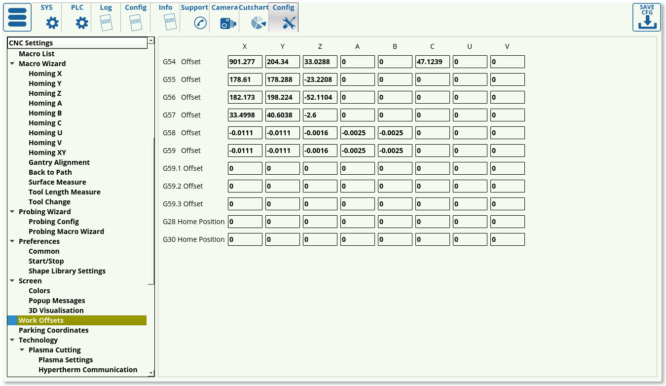
Work offsets
The work offsets list specifies the offsets for each coordinate system (G54 to G59.3).
The home positions for G28 and G30 are also specified in this window, allowing the user to set a preferred home position. These offsets can be set for any axis (XYZABCUV), and are specified in mm.
NOTE: The G28/G30 home positions MUST be set correctly if G28/G30 codes are used in the control program. Failing to set them correctly will lead to the control program stopping at the G28/G30 line and not moving forward in the code as an internal error message will be presented to the program.
A video covering the basics of work offsets:
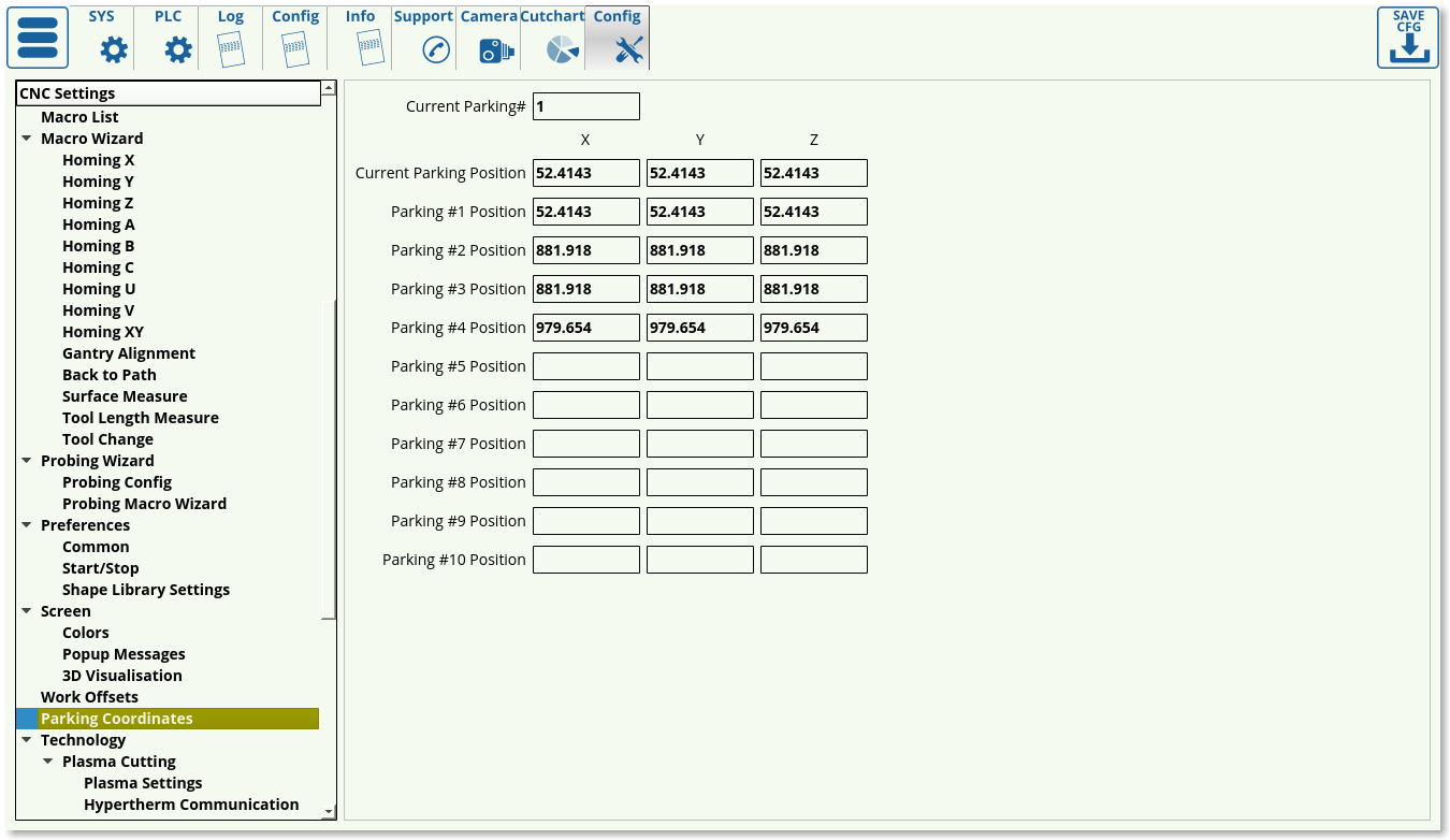
Parking coordinates
The parking coordinates specify the preset parking positions that are saved in the myCNC software for future use. The user can set up to ten parking positions for their convenience, by specifying the X, Y and Z coordinates. The current parking position and the current parking number is also kept in this window.
More info on adding the profile widget to profiles which do not have it displayed by default:
Technology
Plasma Cutting
Plasma Settings
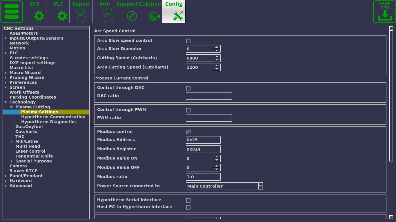
The plasma settings screen allows the user to select the following:
- Arc Speed control (NOTE: As of August 2020, Arc Speed Control has been duplicated to Settings > Motion). Arc speed control can be used on holes or when cutting arcs (such as rounded corners). In this tab you can:
- Enable/disable arc speed control. Note that enabling arc speed control will overwrite the speed F-codes that may be present in the G-code program.
- Arc Slow Diameter. This specifies the maximum diameter for the arc to automatically enable arc / hole cutting speed. If the Arc Slow Diameter is set to 0, arc speed will only be enabled through the M17 macro in G-code (and disabled through the M18 macro).
- Cutting speed (Cutcharts) - this will preload a cutcharts speed, which can then be overwritten by the user. The speed is loaded from the cutcharts only if the Cutting Table option is selected in Preferences > Common > Basic Machine Profile.
- Arcs Cutting Speed (Cutcharts) - this will preload a cutcharts arc / hole cutting speed which can then be overwritten by the user. As with the Cutting Speed (Cutcharts) option, this will be loaded only in cases when Cutting Table is selected and the information is present in the necessary cutchart.
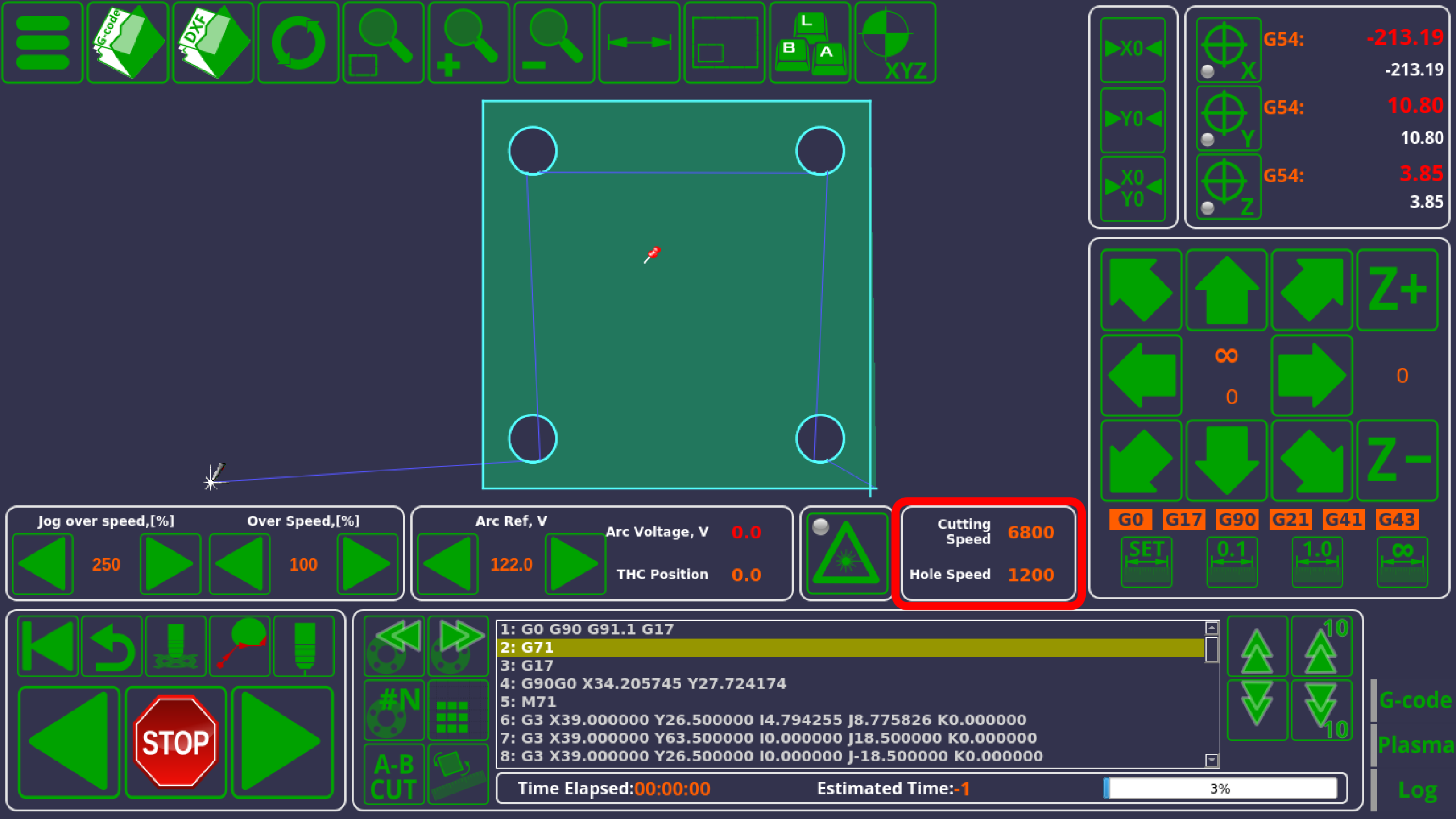
- X1366P profiles have the Cutting and the Arc speed displayed on the main screen (as of February 2020) for the user to quickly reference / change if necessary:
- Current control. Current control can be chosen between Control through DAC, PWM, Modbus or Hypertherm Serial Interface. These are all mutually exclusive - only one can be chosen at a time.
- Control through DAC is the option mostly used for simple plasma cutting machines. The DAC ratio allows the user to set the ratio to convert the value of the current.
- Control through PWM is using the Pulse Width Modulation. It is a popular choice for current control on plasma machines. The PWM ratio allows the user to set the software ratio, similar to the DAC ratio.
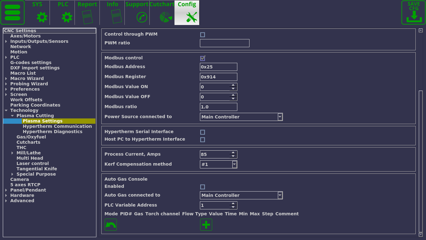
- Modbus control allows for electronic control of the current. More information on Modbus communication can be found in the Modbus Setup manual. The following settings can be specified in this window:
- Modbus Address to specify the address of the device the controller will be communicating with
- The register that will be monitored
- ON/OFF values
- Modbus ratio for the current
- The controller the power source is connected to. Usually, the power source is connected to the main controller, however, on large machines it is sometimes necessary to have a Slave Controller to perform the technology PLC commands.
- Hypertherm Serial interface is similar to the Modbus control option. The user is able to specify where the interface is connected: the controller (default) or the host PC. The Hypertherm Communication and Hypertherm Diagnostics pages are used if the Hypertherm Serial Interface is chosen for current control.
- Process current (amps) which specifies the current for the machine
- Kerf compensation method. Kerf compensation can either be done using a standard mill technique for tool radius compensation, or through a dedicated kerf compensation method made specifically for plasma cutting machines. The dedicated plasma method is on by default, and is labelled as Method 1, while the traditional mill machine method is labelled as Method 2. Below is the comparison of the two compensation methods:
- Note how the two methods are different: Method 1 (plasma kerf compensation) will first move out and then begin the cut, then complete the cut while still using kerf compensation, and will then move back to the original starting point. In contrast, the mill Method 2 will begin and end the cut at the same point, gradually moving outwards to reach the tool width compensation value.
- A kerf value (for plasma cutting) or tool diameter offset (for milling) specifies the offset value. In order for the offset to actually be activated within the program, the G-codes must contain the kerf ON/OFF codes (G41, G42, G40). Most CAM software packages designed for plasma cutting take the tool diameter compensation into account when generating the control program automatically. In those cases, the offset (kerf or toll diameter) compensation must be turned off in myCNC software.
- Auto Gas Console settings. myCNC software allows for gas control using the software PLC commands rather than through the machine. This setting is tailored to the specific customer. If you are interested in the Auto Gas Console settings tailored for your specific needs, please contact the myCNC team through the Contact Us page.
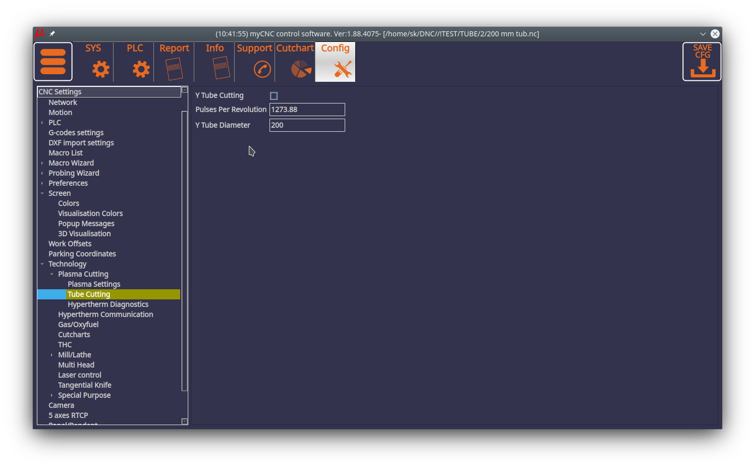
Tube Cutting
Tube cutting is a feature on the X1366P profiles designed for S- and Y-tubes (such as the X1366PYT profile).
The following settings are available:
- Y Tube Cutting enable/disable toggle: turns the tube cutting mode ON and OFF. Toggling between tube and sheet cutting is available on the main screen of the X1366PYT profile (top bar)
- Pulses per revolution: Number of pulses per one full revolution, divided by pi (3.14…)
- Tube diameter: in mm
New tube cutting modes are currently in beta-testing (as of July 2020). S-tube (square tube) cutting will be added in addition to Y-tube cutting in future releases.
The options for switching between sheet and tube cutting are available in the top menu.
Hypertherm Communication
This page allows the operator to send test commands to the Hypertherm machine. The commands can be set to Remote, Hello, Wake, Sleep, Test the gas flow (preflow/cutflow channels), or a custom command.
The screen also allows the user to check the reply log from the Hypertherm machine to see if communication has been established/if any errors are present.
Hypertherm Diagnistics
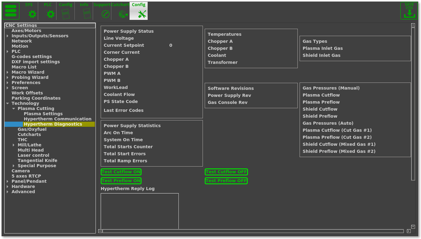
The diagnostics window is useful to see any immediate errors or problems present with the plasma machine setup, either through monitoring pressures, historical usage statistics, or temperature data.
The diagnostics window is used if the Hypertherm interface was chosen for current control. The window allow to check the power supply status for things like PWM/choppers, the statistics for usage time and errors, the temperatures for the machine, the software revisions, gas types and pressures (auto or manual). The window also features a similar set of buttons to the Hypertherm Communication window to test the preflow and cutflow directly from the diagnostics panel (typically to find out the pressures for the plasma and shield gas flows).
Gas/Oxyfuel
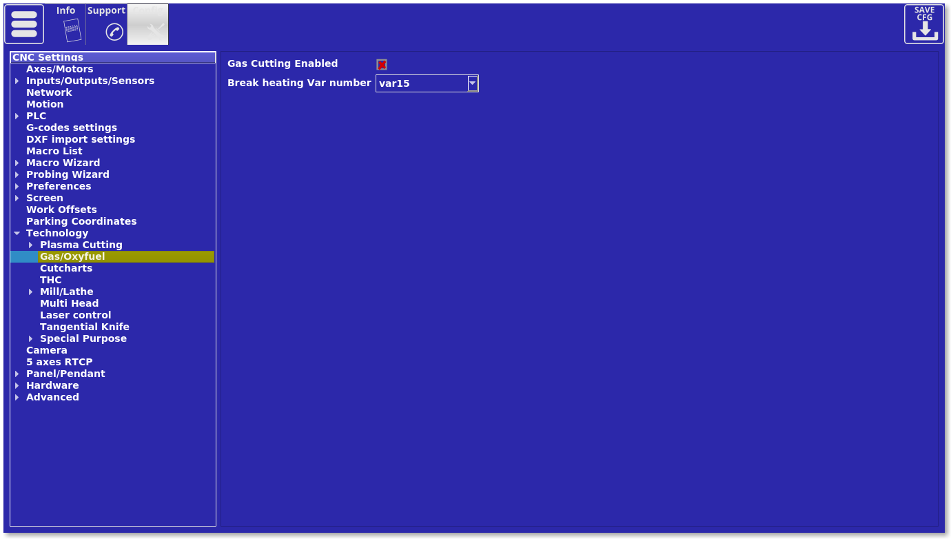
The following settings are available in the gas/oxyfuel window:
- Enable toggle to enable/disable gas cutting
- Break heating variable number. During the preheating process, while the metal is being heated up to its cutting temperature, the operator might decide that the heating process has gone on long enough and stop preheating/start cutting. In order to do that, the operator will typically have a stop button or some sort of control through which the command to stop the preheat is sent to the controller (which would otherwise be using a timer to specify the preheat time, as can be seen in the PLC file). The break_heating variable is used to stop this timed process and move to the next part of the cutting cycle. This number is specified in the vars.h file which can be found in the PLC tab (var15 break_heating is typically used, although other variable numbers can be used on more complex machine setups).
Cutcharts
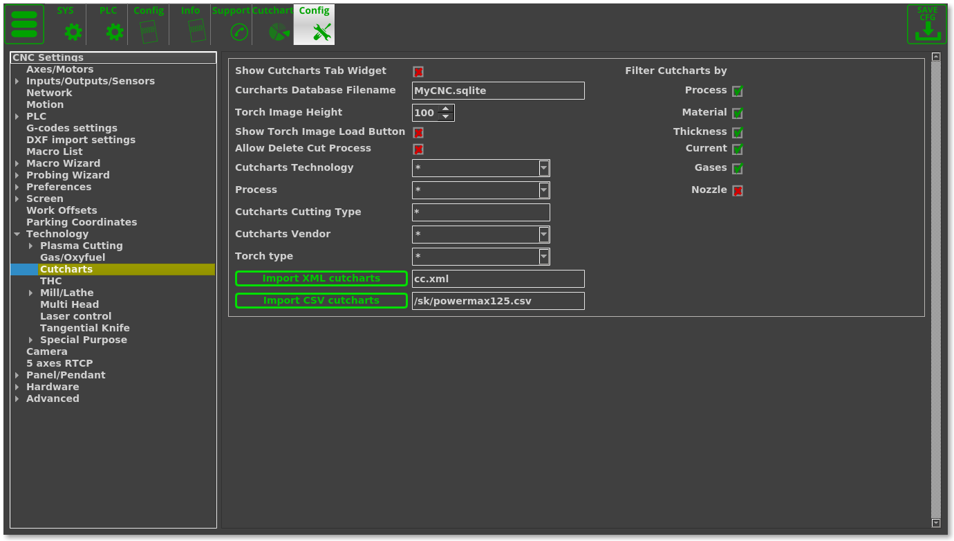
The cutcharts settings window allows the user to edit the cutcharts window and the cutchart information which is often used in the plasma profiles.
The following settings are available:
- Show Cutcharts tab widget toggle. This is a legacy settings that is typically only used on the 1024P series profiles. The setting toggles the cutchart icon on and off so that it can be accessed from the main software screen from the left user panel. Not used on the recent 1366 series profiles.
- Cutcharts Database Filename. This will be the name of the database loaded into the myCNC system, and must be an .sqlite file.
- Torch Image height. The torch image height will define the height of the image field in the Cutcharts tab (Settings > Cutcharts). NOTE: A new cutcharts interface is currently under development to replace the Cutcharts tab in the Settings window.
- Show torch image load button.The torch image can be toggled on/off in the Settings > Cutcharts tab.
- Auto Delete cut process. This settings allows the operator to delete current entries from the cutchart database directly from the myCNC software.
- Cutcharts technology. This allows to chose between Plasma, Normal, Underwater, Bevel, Fine feature, HDi, Marker and Marker bevel. The star symbol (*) symbolizes all categories.
- Process. The following can be chosen: Powemax, FineCut, FlexCut 125, Normal, Underwater, Bevel, Fine feature, HDi, Marker, Marker bevel, or MAXPRO200. The star symbol (*) symbolizes all categories.
- Cutcharts cutting type. Not used in the more recent cutchart database versions, as it has been replaced by the Technology and Process filters.
- Cutcharts vendor can be chosen between Hypertherm or Lincoln.
- Torch type. Powermax105, FlexCut125, HPRXD and MAXPRO200 can be chosen.
- Import buttons for XML and CSV cutcharts. This allows the user to import a cutchart in a different database format.
- Filters for the cutcharts, which include Process, Material, Thickness, Current, Gases and Nozzle. These specify which categories the user will be able to filter the cutcharts by from the cutcharts window,accessed from the main screen of myCNC software.
THC
This is part of the Torch Height Control Setup which is used on plasma machines. Please consult the THC article for more information.
Mill/Lathe
Spindle
- Spindle Speed, [rpm] - A minimum and maximum range of the spindle, a step value (current spindle speed will be increased/decreased by this value while pressing on-screen SpinBox Default Spindle Speed). Maximum spindle speed value is used to adjust 0-10V analog DAC output as well.
- Spindle Overspeed, [%] - A minimum/maximum range of Spindle Overspeed, a step value (current spindle overspeed will be increased/decreased by this value while pressing optional on-screen SpinBox Spindle Overspeed). Both “Default Spindle Speed” and “Spindle Overspeed” can be used to adjust spindle speed on-the-fly, however these are different parameters
- Default Spindle Speed will be overwritten when the next M3 Sxxxx or Sxxxx code is run. For instance, if you change the spindle speed to 12000rpm, then when M3 S8000 appears G-code, spindle speed will be changed to 8000 rpm
- If the Spindle Overspeed, [%] value is changed, it will be applied for next Sxxxx code as well. For instance, if the current spindle speed is 5000 rpm and you set the “Spindle overspeed” to 120%, spindle speed will be increased up to 6000rpm (5000rpm*120%/100%). Then when the M3S8000 code appears in the G-code program, the spindle speed will be raised up to 9600rpm (8000rpm*120%/100%)
- Encoder channel. If feedback encoder is installed on the Spindle for threading, it might be configured in this field. Control boards ET5 and ET10 have 6 encoder inputs (with a hardware decoder), ET7 has 3 encoder inputs (hardware decoding as well). Encoder channel # should be configured here.
- Encoder pulses per revolution. If Spindle Encoder feedback is used, the number of encoder pulses per spindle revolution should be set in this field.
- Voltage offset, units - see below
- Voltage ratio, units - these two parameters are used to adjust DAC output voltage.
These parameters are active in case RS485/Modbus Communication is disabled
There is a 12bit register that is used for the DAC output. In theory, while writing values from 0 to 4095, the DAC output voltage is changed from 0 to 10V. A real maximum DAC voltage depends on the control board and can be 11-12V. However, while most of Spindle frequency inverters use 0-10V, there are many models on the market that use different voltage range for spindle speed control such as 0-5V, 1-6V, 0-6V.
If spindle speed changes (for example, through the PLC procedures such as M03, M04, SPN) the control software sends the spindle speed value to the PLC commands in the eparam variable. The value is adjusted by the software by using the parameters offset and ratio. Eparam variable value can be calculated aseparam = Offset + 4095*(Spindle Speed)*Ratio/(Max Spindle Speed)
- If you don't need any adjustments, set the Offset to “0” and the Ratio to “1”.
- If you use a spindle inverter with 0-5V range for instance, then you might need to set the Ratio to “0.5”
- For spindle range 1-6V you might need to set the Offset as well. Minimum voltage is “1V”, then Offset should be about 10% (1V of 10V) of 12bit range (4095), the Offset value is about “410”.
It's better to tune Offset and Ratio values by experimenting with the possible values with the real VFD unit connected to test for optimal results.
- RS485/Modbus communication. The checkbox enables communication with VFD through the RS485/Modbus instead of analog control. You can learn more about Modbus in the Modbus Setup manual.
- Spindle ratio (Modbus). If Modbus is enabled, the myCNC control software sends the RAW spindle speed value (in rpm) multiplied by Spindle ratio (Modbus) parameter value as an eparam variable to the PLC procedure .
- For instance, if the Spindle speed is 10000rpm and the Speed ratio (modbus) is “1”, then the eparam value will be “10000” (exact spindle speed).
- If the ratio variable is not enough to adjust Spindle speed register according to the VFD type requirements, this adjustment can be made in the PLC source.
- RS485 speed - RS485 communication baud rate selector
- Connection - RS485 connection configuration
- 8 or 7 bits
- No Parity, Odd or Even Parity
- 1 or 2 stop bits
- Inverter Address - up to 4 VFD can be connected through Modbus to arrange 4-spindle automatic polling. It needs to select the checkbox and set up Modbus ID for each VFD to enable VFD automatical polling
- Write Registers. For automatical Modbus polling registers, there are usually 2 control registers for VFD.
- Frequency (Spindle Speed) is changed by writing to “WR/Frequency” register
- Spindle control ON/OFF by writing some value to “WR/Operate” register.
Register addresses should be specified in these parameters
- Read Registers. VFD might have some status/diagnostic registers to read. The values may contain useful information such as the current power, current speed, temperature, errors, current status etc. You may select some register to perform automatic readings and to show the value in this window.
- “Write registers” and “Read registers” are different for different VFD manufacturers. We have pre-defined register addresses for the VFD inverters we tested. To set up register addresses, simply press the button with your particular VFD type.
For example, for a Delta EL connection via Modbus, the Read registers will look the following way:
The “Read registers” values specified for read access are copied to variables # 8310 … # 8315. The values of ordinary registers can be displayed on the screen using standard methods (LEDs, digital values, graphic elements such as thermometers, etc.).
Access to these variables is also available from the PLC, so you can implement some additional features, such as movement when when a set speed is reached (as opposed to movement by timeout), monitoring spindle rotation during operation, overheating errors, etc.
Tools
The tools page allows to outline the specifications of existing tools such as their length, diameter and offset.
The following settings are available:
- Tool lift, to specify safe travel distance for the tool.
- Tool list, which lists the available tool numbers separated by semicolons.
- Tool length for the Z axis (vertical), in mm
- Tool Diameter, in mm
- Tool Offsets for the X, Y and C axes. The tool offsets are done relative to some base/main tool which is considered to be at a 0 offset for all axes, and the rest of the tool offsets are recorded in relation to that main 0-offset tool.
ATC Pots
CURRENTLY UNDER DEVELOPMENT. This feature is designed for machines with long automated runs.
The following settings are available:
- Tool number. A single tool number can be assigned to different pots, unlike in conventional machining. This way, separate pots can be used for storage of the same tool (or a tool with the same number which will later have its length measured).
- Broken toggle. This toggle specifies whether the tool is broken based on the length measurement (if it is considerably lower than the original length measurement).
- Last length stores the length measurement of the tool on the last length checkup
- Working time. Working time and the broken toggle can be reset by using the Reset button next to it if the tools have been replaced with new ones.
- Max time specifies the maximum working time until a tool will have to be replaced by another tool with the same number from the next pot.
- Pot coordinates XYZ.
Lathe
The following settings are available for lathe machines:
- Enabled/disabled toggle. This toggle signifies whether lathe-specific G-codes will be used (such as G70, etc). This setting has been largely taken over by the Basic Machine Profile setting in Preferences > Common
- X position as diameter: the X position is typically inputted as a radius (if x=10, then the radius is 10). This setting exists for those users that would rather input x as diameter (x=10 means that the radius is 5).
- Thread cutting depth infeed. The different types of infeed can be chosen here. 1 edge means that a single edge of the cutting tool is used to enter into the metal, while 2 edges means that both edges are used interchangeably in a crisscross pattern. The constant depth setting means that the tool will go into the metal by the same depth on every pass, while constant amount means that the same volume of metal will be removed every time (while depth will diminish as the tool goes deeper). NOTE: 2 edge configurations are currently under development and may pose some issues. Contact Support for more information.
- 2 lines G76 describes the format in which G76 commands are written. If the setting is selected, two lines of code description will be required.
- G96 CSS max speed specifies the maximum Constant Surface Speed that the machine is allowed to go up to. As the lathe will attempt to maintain constant speed while the working radius gets smaller, the speed will continuously increase. In order to prevent the machine from trying to increase the speed to infinity, a limit should be set.
- NOTE: Overspeed acts in a manner similar to CPU overclocking. Motion acceleration is increased together with motion speed when the overspeed is increased. Since toolpath planner does not have access to “Overspeed” value, a significant increase in Overspeed value up from 100% may cause issues, especially for analog servo control. Overspeed should be limited to 100% if you need to be sure the machine does not exceed “Max Speed”.
- G96 CSS mode active selects when the Constant Surface Speed is activated. Normally, it is done only on G1/G2/G3 commands when the program is moving the working tool. However, it can also be set to All Motion in order to allow manual movements of the lathe's working tool to also trigger the Constant Surface Speed macro.
- Tool number input format specifies the format the tool number is recorded in. The possible formats are XX, XXYY, and XXYYZZ. These different format can specify the tool length and correction values, and should be chosen depending on how the tool numbers are written in the code. Correction numbers can be different for the same instrument, depending on the particular tool usage required at that particular point in the code.
- Thread finishing distance % is used on the last thread turns, to specify by how much the final rotation should go around (for example, the last thread turn can be a 50% turn which would then taper into nothing).
- Thread Acceleration Multiplier, to specify acceleration values on thread cutting
- Tool list, listing the available tools
- Tool specs table, listing the tool numbers, tool lengths in the x and z direction (negative values), x and z tool compensation, and tool tip radius.
Multi Head
Multi Head allows for multiple tool sets. Similar to the Tools window, in that it allows for tool offsets in X and Y axes. Overall, the following settings are available:
- Tool number
- Offset X, Y which are done relative to some zero position
- Unlike the XY offsets, the Zero Z coordinate is not changed from this window, but rather through the tool length measure and surface measure procedures (to specify the offset in the z-axis).
Laser Control
Allows for fine laser control at different speeds. This allows to prevent overheating when approaching corners, etc.
The following settings are available:
- Enable/disable toggle
- Min/Max control values. This allows the user to set values from 0 to 99 percent of the total laser power.
- Speed ranges for min/max values set the speeds range in which the laser power will be changed between the two values set above (everything below the min speed value will be at min control value, everything above the max speed value will be at max control value, and in the range in-between the two speed values there will be a linear transition between the two control values).
- PWM channel to specify the channel designated for laser control
Tangential Knife
The full manual for the knife setup and the knife behaviour can be found at the QuickStart page for Tangential Knife Setup
The following settings are available:
- Knife Minimum degrees (1 and 2)
- Knife Up programming (absolute/incremental)
- Knife initial angle (angle after homing)
- Glass cutting extension toggle
- Lift height
Special Purpose
Flatbed correction
Flatbed correction allows the user to take into account an uneven working table. This is done by first measuring the table and then using the values to correct for what would otherwise be discrepancies in the z-axis.
- Enable toggle to enable/disable flatbed correction
- The table on this settings page presents a number of values in the XY-plane and their z-positions. These values can either be recorded by using the AutoMeasure procedure (recommended) or by using a sensor and recording each point individually by using the M402 macro (older versions).
- Using the AutoMeasure procedure, the operator can set the reference z-height, the number of points at which the height measurements will be taken for the XY-plane, and the coordinates on which the measurements will be taken. The Auto Measure Procedure button can then be pressed to begin the probing process.
- In order to use the M402 macro, move the sensor to the position you want to measure, then press the Measure (M402) and Save button. This will lower the sensor down until contact, then lift it back up and record the z-position at which the sensor was triggered.
- In order to remove any of the table level discrepancy values, you can press the Delete button for each particular value.
By adding these correction points, myCNC software will use triangulation in order to create a complete updated map of the working table. From here on, whenever Flatbed Correction is enabled, the machine will automatically adjust the z-axis height of the working tool in order to adjust for the table level changes depending on where in the XY-plane the machine is currently located.
Height map
The height map window specifies the axes to log, the log header, the format string, and the file name for the map.
The height map is typically utilized for the per-job height probing described in the 3D Height Mapping manual. It is necessary to change the filepath to include the correct username for the machine (for example, /home/USERNAME/heights.map) as opposed to the default username specified in myCNC software (sk/mycnc/etc).
The height map file will be then saved as heights.map.raw file with an array of XYZ points stored in it to create a height map of the working surface through triangulation.
3D Printer
The 3D printer Config window monitors the two thermal sensors which measure ADC signals and convert them into temperature values in degrees. This is necessary as there is no direct way to display the ADC outputs in a meaningful way without first converting.
Related to the 3D printing setup, the Axes/Motors Config window allows to set a motor for axis E (extrusion), which controls the rate at which the working material is being extruded, or the X+Y, X-Y motor axes. These are designed for 3D printer configurations where two motors are connected to the same working belt, which is then used to move the machine. The motors attached can therefore be used for both axes, depending on which combination of motor movements is used.
Multi-Device
The multi-device window allows the user to set up master/slave relationships between controllers, with one master and multiple slave devices.
This is done by using their IP addresses and specifying there PLC procedures in the PLC Rom setting (available upon request). The Inputs window allows to use the input ports of the slave controllers as alarms or triggers. This is similar to the Inputs/Outputs/Sensors > I/O Expand cards mapping window, as it allows to use ports from other devices if the main (master) device needs to have its ports expanded. The Multi-Device window however allows for a much more extensive and complex setup, and should be used on machines which would otherwise be limited by the simpler I/O Expansion process.
The Test and PID config tabs are special purpose only, and should not be used by regular users.
MaxLaser
MaxLaser allows for laser etching/marking to be used in conjunction with plasma cutting, typically to be able to easily identify the parts that are being cut by recording their number, etc.
The following settings are available:
- Laser speed, in mm/min
- Power, in percent
- Laser frequency, in kHz
- Scan value to specify how close together/far apart individual etchings should be
- Repeat value to go over the same line multiple times
- Text outline toggle
- Text fill toggle specifies whether the user wants to fill in the letters or leave an outline only.
- Font settings (font and size) - multiple fonts are supported
- Line direction (horizontal/vertical)
The user is able to print sample text by using the Print Text buttons and inputting sample text into the Test Line field.
An example of the MaxLaser technology being used by one of myCNC's customers (used in conjunction with a plasma cutting process in order to easily identify individual parts):
Circular Saw
Special user case settings for a saw machine setup. Information available upon request, as the setup has been fine-tuned to a specific machine and may need extensive alteration for new customers.
PWM PIDs
This settings window allows for PID control by using PWM and ADC ports to create a PID control loop.
For example, PID control is used in the 3D printing setup for temperature sensor control. This window allows to edit the following values:
- K0 (offset value for the ratio that will bring the curve up/down)
- K (ratio value to multiply the result by)
- P - proportional gain (proportional control ratio)
- I - integral gain (integral control ratio)
- D -derivative gain (derivative control ratio)
- Dead zone, which specifies a range in which inputs are outputted as a zero value
- Control Min/Max signifies the bounds for the PID PWM control
- Sensor Offset allows to take into account sensors that do not start at zero (for example, a sensor that goes 1-5V)
- Sensor ratio (1/1024) - scaling coefficient to convert the result from some raw input value into the expected value range
A manual on using PWM PIDs in order to control an Automatic Gas Console is available on this page.
Modbus servo
Deprecated settings window, not used in the recent software versions. Has been replaced by full Modbus setups, information on which can be found in the Modbus Setup manual.
Exhaust/Extraction control
Exhaust control is done to allow for exhaust pipes on the machine to open depending on where the working tool currently is.
The following settings are available:
- Axis (X/Y/Z). Typically exhaust control is built for one axis, as it would be too complex for typical machines to create a 2- or 3-axes setup (only one row of exhaust pipes is normally used)
- Min and max positions specify the minimum and maximum coordinates for the exhaust control (the coordinates from the specified axis that would turn ON a particular exhaust pipe). Therefore, it is necessary to add as many individual setting fields as there are exhaust pipes that need to be turned on/off.
- Slot specifies the port that will be switched on/off. This can be a relay/PWM port/etc.
- Inversion toggle to specify whether the exhaust should be turned on or off by default (while the working tool is not in the exhaust pipe coordinate range)
Camera
The camera system allows to correct an imported DXF file if the working material has been stretched/compressed/rotated by using reference markers (also known as registration markers, or fiducial markers) that have been calibrated using myCNC software.
For a full overview of CNC Vision Camera setup, please consult the QuickStart CNC Vision manual.
5 axes RTCP
This setting allows to set up the rotational tool center pointer for bevel cutting on 4/5 axes machines.
RTCP allows to compensate for a rotation of the working tool (that would otherwise lift up due to moving from a 90 degree position to a 60 degree position, for example). The following settings are available:
- Enabled/disabled toggle
- RTCP kinematics. 0 is off, 1 and 2 are the different correction options. As of version 1.88.3271 of the myCNC software, only options 0/2 should be used (1 will not work for a vast majority of setups).
- Arm length. This specifies the arm length from the pivot point to the end of the working tool. Note that this does not specify the entire length of the moving part, but only the length from the pivot down (as this is the part that will be used in the angle calculation for the rotation compensation).
- Inversion toggles for X, Y and Z axes that can be used to flip the positive/negative directions for each of the axes used.
- Test buttons for RTCP ON/OFF. This allows to quickly turn off the compensation when it is not necessary (for example, during homing, etc).
- RTCP Debug, which should only be used by service engineers when diagnosing an issue.
NOTE: RTCP should only be enabled after homing procedures have been completed and the working tool is solidly in the 90 degree position (vertical).
NOTE #2: RTCP can be used by both 5-axes setups and for the 4-axes setups where the software assumes one axis to be equal to 0.
Panel/Pendant
Wireless Pendant/XHC
The full manual can be found at the Wireless Pendants page, including the list of all possible commands/actions that are used in the Wireless Pendant, Operator Panel, and other config dialogs.
Operator Panel
The operator panel is similar to the wireless pendant in that it allows to set up a separate input mechanism from the traditional screen/keyboard. It allows to set up a connection between the pressed keys and actions which are listed in the Wireless Pendants manual.
- The Serial Communication section outlines the connection information and allows the user to load some default sets of keys. Keys can also be imported from a file which is located in the
- Keys can be set to trigger a certain action both when pressed and released. It is possible, for example, to set up a key which would pause the program when pressed, and then start it up again when the key is released (list of actions available here).
Gamepad
Allows the user to take control of the machine through a joystick/gamepad controller.
After connecting a gamepad to the host computer, the following options are available:
- Enable/disable toggle for gamepad control
- Joystick/gamepad selection field.
- Joystick settings. It is possible to assign both axes (up/down and left/right) of the controller joysticks to a movement in the negative/positive XYZ axis for the machine. The directions can also be flipped by scrolling through the movement options (such as left = positive X and right = negative X, or vice versa).
- Each of the controller keys can be defined to perform some action when pressed. The full list of the possible actions can be found in the Wireless Pendants manual.
- Hat #0-9 can also be assigned some actions. Hat 0 specifies the default position of the arrow keys (with no keys pressed), and can also be assigned some action or command (for example, to trigger when one of the arrow keys is released).
Another option for joystick control can be found in the Jog through ADC inputs section of myCNC settings.
Hotkeys
The Hotkeys settings window describes the possible hotkeys which are present in the software. These keys allow the user to control the machine directly from the keyboard, by using some commands which the user can assign to different actions.
By default, the Shift and Control key are used to set different values of the Jog Overspeed %, allowing the user to quickly control jog speed with a single press. These can be set to be at different percentages (10 and 100 by default, with an allowable range of 5 to 150).
The hotkeys for moving the axes are also set in this dialog window by assigning each particular axis direction to the arrow keys.
A list of default hotkeys is provided in the table below:
| Hotkey | Action |
|---|---|
| Arrow up | Move tool (default is Y+, direction can be reassigned) |
| Arrow down | Move tool (default is Y-) |
| Arrow left | Move tool (default is X-) |
| Arrow right | Move tool (default is X+) |
| PgUp | Move tool (default is Z+) |
| PgDn | Move tool (default is Z-) |
| 1 | Zoom out |
| 2 | Move visualization up |
| 3 | Zoom in |
| 4 | Move visualization right |
| 5 | Fit to screen |
| 6 | Move visualization left |
| 8 | Move visualization down |
| R | Back to working point |
| T | Run program (cut from edge) |
| A | Reload program |
| S | Stop program |
| G | Run program |
| Ctrl + X | Restart GUI |
| Ctrl + Z | Save current profile to archive |
| Ctrl + N | Next line |
| Ctrl + P | Previous line |
Additionally, nearly any unassigned key can be assigned to have an action associated with the keypress, similar to the pendant setup described in the Wireless Pendants manual. These keys allow the user to effectively employ the keyboard as a wireless pendant, controlling machine movements and running PLC procedures/actions, changing global variable values, and more. This is done by selecting:
- The key combination (whether Ctrl, Alt, Shift are used, and the specific key assigned)
- The state (pressed or released) which will trigger the response. Both of these can be chosen for the same key combination, triggering one action on key press and another on key release.
- The particular action (read more about actions in the Wireless Pendants manual).
- Specific command (if applicable to the particular action, as some simpler actions don't require a specific command).
NOTE: For things such as jog, it is often required to use both the “pressed” and the “released” commands for the hotkeys/hardkeys within the myCNC software:
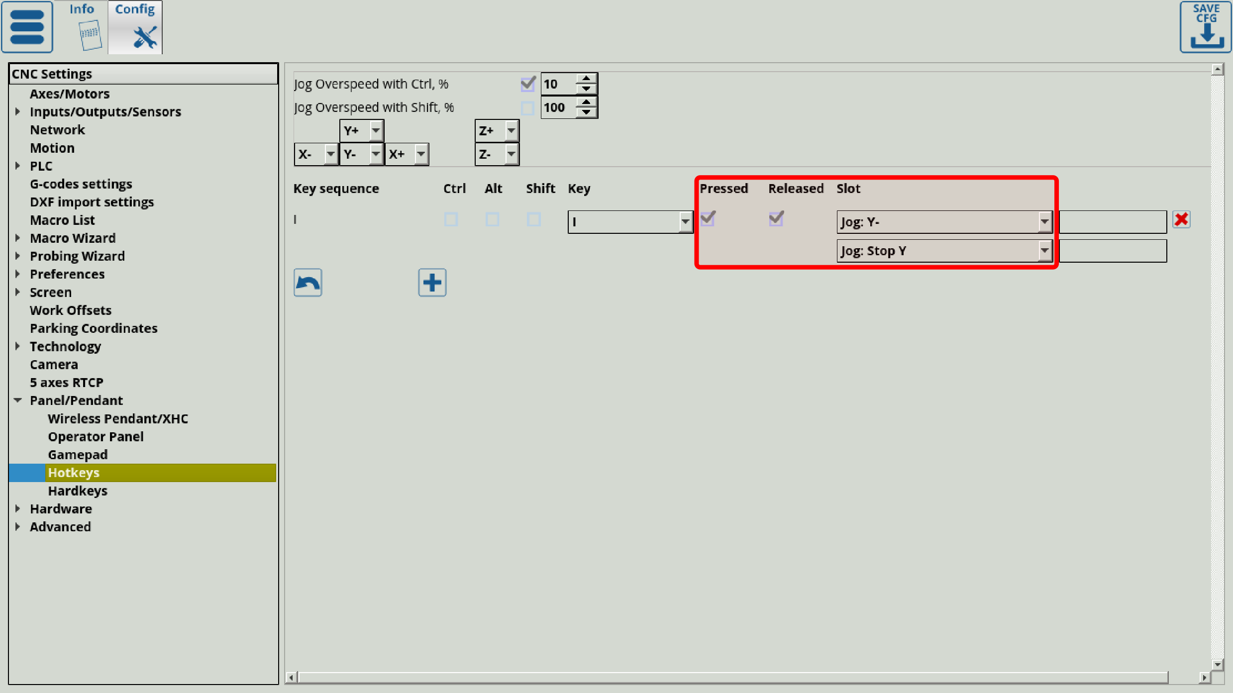
NOTE: Your system keyboard shortcuts can override the myCNC program shortcuts. For usability purposes, it is recommended to disable unnecessary shortcuts in your system to not conflict with the myCNC application. There can be found in your OS settings. For example, Ubuntu MATE shortcuts can be found by searching for the Keyboard Shortcuts setting in the Main Menu:
Hardkeys
Hardkeys allow the user to connect a button or a key directly to the myCNC controller which will then cause a certain event when pressed/released.
The following settings are available:
- Input Number, which specifies the input to which the hardkey is connected (can be checked in the Diagnostics window)
- Pressed/released specifies the state to activate the corresponding event. This is similar to rising/falling edge on the triggers setup.
- Autorepeat generates the rising edge continuously. This behaviour is useful when the button long-press needs to correspond to a gradual increase/decrease in some value, allowing to input some changes over time by continuously transmitting a rising edge signal.
- Slots describe the available events, which are the same as in the Wireless Pendants manual, ranging from job stop/start for quick controls, to jog commands, to running a particular PLC procedure. Please consult the Wireless Pendants list to find out more about the particular Slots and Parameters.
A tutorial video on setting up a set of hardkeys for machine jog (movement) is available here:
NOTE: For things such as jog, it is often required to use both the “pressed” and the “released” commands for the hardkeys/hotkeys within the myCNC software:

Hardware
Common Hardware Settings
- The Common Hardware Settings allow the user to invert any input/output value, depending on which particular default configuration is preferred. The table goes the 0-63 inputs and 0-63 outputs values, with the red cross symbolizing OFF by default and the green check mark symbolizing ON by default behaviour.
- The Input Pins Filter is set up to filter noise and random input on the controller inputs. Raising the value in this field will raise the amount of time necessary (in ms) to continue supplying the same input to the controller through the inputs for the controller to register the change. Setting this value to zero will disable the delay. AS OF NOVEMBER 2020, ONLY IMPLEMENTED FOR THE ET7 AS A PROGRAMMABLE OPTION.
- Max value of 1.62 seconds on the ET7
- For ET10 filtering is currently fixed at 0.16 ms.
- Note that the fast encoder inputs (#20-#25 for the ET7 board) are not affected by the filtration to not introduce unnecessary delays.
- The Keypad filter performs a similar function to the Input Pins Filter, by introducing a delay in which the panel key has to be held continuously for the system to recognize the key press. Setting this value to zero will disable the delay. Max value of 250.
- ADC inputs can be inverted similar to inputs/outputs inversion
- Pulse Width is set up in the Common Hardware Settings. To learn more about this, read the MyCNC Pulse Width Setup manual.
- The pulse format can be chosen between pulse/dir or cw/ccw formats. The pulse/dir format has the step and direction inputs. Step input accepts a pulse signal which determines angle and speed of rotation. Direction input receives either high or low digital signal that regulates direction of rotation. The CW/CCW mode, on the other hand, has CW and CCW inputs. Pulse in these inputs determines whether the motor rotates clockwise or counter clockwise. This setting depends upon the hardware that the setup is using.
- UART2 Setup can be chosen between External myTHC, IPG Laser Control, Modbus #2, Hypertherm Interface or Capacitive Height Sensor.
- External myTHC: Deprecated, was used as an external Torch Height Control which would be attached to the controller and exchange arc voltage information, etc. As the THC process has been integrated into the newer control boards, this function is only used on older boards.
- IPG Laser Control: Deprecated, was used as laser control through UART2. If any users require this control, please contact myCNC Support.
- Modbus #2: Under development. The feature allows to use the controller as slave (rather than master), with gvariable commands being sent to it by some other device.
- Hypertherm Interface: Used for the HPR series Hypertherm machines, as those use a different protocol from Powermax/XPR series machines.
- Capacitive Height Sensor: Deprecated, was used on the machines running a capacitive height sensor which would transmit the height information to the controller through a digital (rather than analog) signal.
- Command buffer size is chosen between 8k and 16k. 16k is always chosen for newer firmware (after November 2015) and on all the newer boards. Only the ET1/ET3 boards with firmware which has not been updated use 8k.
- ET6-ET10 overspeed bugfix toggle - this setting is not useful for the newer boards, as those automatically transmit their firmware version to the myCNC program. Useful on older ET6/ET10 boards as the overspeed parameter was counted differently on those from the more recent ET3/ET7 boards.
Encoders
The Encoders config window allows the user to fine-tune encoder settings. This window is typically not useful for simple tasks (such as using a rotary encoder to control overspeed, etc), as it allows for further finetuning of the encoder values.
The following settings are available:
- Encoder Number Lines for each particular encoder - this allows to specify the total number of lines/markings per one full rotation of the encoder wheel (note that this is different from the total pulses per one rotation, which would be specified in Settings > Config > Inputs/Outputs/Sensors > MPG through binary inputs).
- The current encoder value is displayed on this screen. This is the fastest way to check if the encoder is connected/working - for example, turning an MPG wheel handle should immediately change the current encoder value in this field for the selected encoder.
- Z-position is displayed
- Mul coefficients, as well as /(2^Div) values. These Mul and Div coefficients are used due to the fact that the controller cannot handle floating number data in calculations, therefore it is necessary to first multiply and then divide a number by certain coefficients. They are used to bring the value of the encoder in line with the pulses/unit value specified in the Axes/Motors tab. Larger numbers allow to reduce the error. For example, if the ratio between the Axes/Motors value and the encoder pulse/unit value is 3.5, then the multiplication value (Mul) can be set to 7, while Div can be set to 1 (2^1 =2, 7/2 = 3.5).
- Encoder position
- Position
- Attached to motor flag (has been moved to Analog and Pulse-Dir Close Loop settings in the recent software versions).
More information on encoders is available in the Rotary encoder connection and setup manual which goes through some connection examples. Additional information on using the ET10 encoder inputs with an MPG wheel is avaialble in the MPG through binary inputs manual.
Analog Closed Loop
This allows to create an analog closed loop system with PID controls. More information on PID control and closed loop configurations is available in the MyCNC closed loop configuration manual.
The following settings are available:
- Enable/disable toggles for each motor
- PID ratio K
- Ratios K0, Kp/1024, Kd/1024, Ki/8192. These can create an experimental ratio for K, which can be copied into its respective field by using the arrow button in each motor line. Therefore, it is not necessary to input the K ratio initially. However, the time to find this experimental ratio will be a lot higher that if the ratio has already been inputted, so this method is not recommended for day-to-day operations.
- The integral limit, which prevents Ki from going above a certain value as the integral control part of the PID control system can lead to issues due to Ki being too large and not adjusting fast enough if there is a problem with the motor.
- Encoder channel specifies which channel the motor is linked to
- Dead zone - a range of input values where the output value is zero.
- DAC offset. Typically, we are looking at a range from -10V to +10V, which translates to 0-4095. As each motor has their own offsets, the DAC Offset value allows us to take that into account.
- FError value
- S.EN port - servo ON command
- Position Error and Speed Control values window which allows the user to monitor these values in real time by assigning a colour to each of the eight motors.
- Buttons for motor control are available at the bottom of the page, which allow the user to quickly see how each motor reacts to an input and what the error/speed values would be.
- The servo-motor ON/OFF buttons allow the user to abort the process if one of the constants has gotten out of bounds and an overcorrection is imminent (for example, if there will be a sudden jerk or impact due to one of the motors overcompensating). This will turn the motor system off, and instruct it to count the current error as zero on the next start up.
Such a system can have its Mul/Div ratio set to be at 1, as it is not required to bring it in line with the Axes/Motors pulse/unit values.
Pulse-Dir Closed Loop
This window allows for fine-tuning of PID control for pulse-dir closed loops. More information on the PID control is available in the Encoder/Analog Closed Loop sections above, as well as in the MyCNC closed loop configuration manual.
In this case, it is necessary to set a proper ratio using the Mul/Dir coefficients from the Encoder window. The following settings are available:
- Enable/disable toggle for PID control of each motor
- PID ratios K0, Kp, Kd, Ki
- Integral limit, which prevents the Ki (integral control) ratio from going unreasonably high, as the integral control part of the PID will take a long time to come back down to normal.
- Encoder channel which signifies the channel denoted for each specific motor
- Dead zone, in which the input values will be equal to zero at the output.
Overall, the setup for this window is similar to the Analog Closed Loop setup earlier.
ET2/ET4
Host Modbus
This is part of the Modbus device setup, and is part of a longer manual series which can be found here: Modbus Setup.
This section deals with Modbus communication with the host computer (the description of the setup can be found in this manual: Host Modbus API).
The following settings are available in the Host Modbus config settings window:
- Enabled/disabled toggle
- Port to be used for the connection from the host computer to the Modbus device
- Baud (typically set to be at 9600, 8, N, 1).
- Timeout, in ms
- Number of retries for a failed message delivery
Advanced
Profile
This window lists all the relevant profile xml files which define how the screen, settings, etc are laid out. These files should not be edited unless strictly necessary, as it they define the entire screen layout, the current settings config, the tools, and more.
Debug
The debug window allows the user to create a debug log file. Typically not useful for end users, mostly for technical support and repair engineers.
UI Settings
The UI settings allow the user to edit their on-screen UI.
- Allow to edit cnc-screen.xml is an experimental feature which should be used with caution, as it allows editing of most on-screen elements and can lead to unforeseen consequences. It is mostly used to look up button functions that might not be otherwise obvious. Currently, if the save button is pressed during the editing process, a new .xml file will be created in your profile's folder, titled cnc-screen-custom.xml. If this is the case, a blank screen will be presented to you during the next program loading, with the entire screen erased. To fix this, navigate to your profile's folder and delete the new custom file (the old cnc-screen.xml will still be intact as it is not impacted by the changes).
- The user is able to select particular tabs to display on the main screen, such as the Vars tab, Diagnose, Library and others.
- Tabs shown after pressing the Settings button from the main screen of myCNC software can also be configured here. These include System, Support, PLC, Stats, Log and Cutcharts tab.
- The user is also able to edit the appearance of the Tools window on the main myCNC screen from the UI Settings tab. The UI Settings tab allows you to select the necessary elements of the Tools window by setting the check marks next to the necessary UI options:
