mycnc:alarms
Alarms
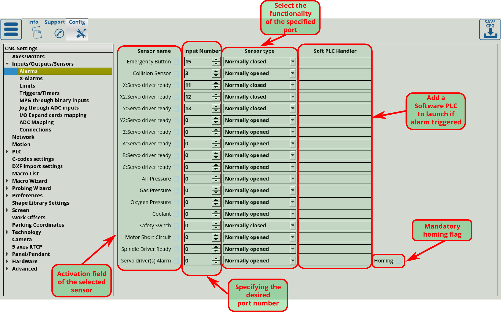
This section allows you to specify the alarm inputs and the response to these sensors. To navigate to it, you can head into your Main Menu > Settings > Config tab > Inputs/Outputs/Sensors > Alarms.

- The selected sensor is activated by setting the “V” symbol in the corresponding field:
- The input number on the controller board is set in the corresponding field “Inputs Number”. Numbering of inputs can be found in the documentation for the selected window controller:
- The type of the sensor is specified in the corresponding field “”. There are two types of input sensors. Normally open - the sensor in the rest position has open contacts and in the course of operation the sensor contacts are closed. Normally closed - the sensor in the rest position has closed contacts and during the operation, the sensor contacts are opened. This “normal” behaviour can be reversed in Settings > Config > Hardware > Common Hardware Settings > Input Bits Inversion:
* Additionally, the program can launch a Software PLC command when an alarm is triggered, by specifying a Software PLC handler in this next field:
 You can read up more on Software PLC programming (and PLC programming in general) here: PLC
Table of alarm sensors
| Name of alarm sensor | Functional of sensor |
|---|---|
| Emergency Button | Emergency shutdown button. When the button is pressed, all machine actions will be stopped. |
| Shock sensor | Tool holding sensor. Usually, this sensor is installed directly in the place of attachment of the instrument and is designed to protect the tool against damage when the tool hits the obstacle. |
| X:Servo drive ready | The signal generator of the signal for readiness to move the drive along the X coordinate. As a rule, the source of the signal is directly the drive of the corresponding coordinate. |
| X2:Servo drive ready | The signal generator of the signal for readiness to move the drive along the Y coordinate. As a rule, the source of the signal is directly the drive of the corresponding coordinate. |
| Y:Servo drive ready | The signal generator of the signal for readiness to move the drive along the Z coordinate. As a rule, the source of the signal is directly the drive of the corresponding coordinate. |
| Z:Servo drive ready | The signal generator of the signal for readiness to move the drive along the Z coordinate. As a rule, the source of the signal is directly the drive of the corresponding coordinate. |
| A:Servo drive ready | The signal generator of the signal for readiness to move the drive along the A coordinate. As a rule, the source of the signal is directly the drive of the corresponding coordinate. |
| B:Servo drive ready | The signal generator of the signal for readiness to move the drive along the B coordinate. As a rule, the source of the signal is directly the drive of the corresponding coordinate. |
| C:Servo drive ready | The signal generator of the signal for readiness to move the drive along the C coordinate. As a rule, the source of the signal is directly the drive of the corresponding coordinate. |
| Air Pressure | A sensor for the availability of sufficient pressure or air flow in the system. Typically, this sensor is installed directly at the entrance to the machine. |
| Gas Pressure | A sensor for the availability of sufficient pressure or gas flow in the system. Typically, this sensor is installed directly at the entrance to the machine. |
| Oxygen Pressure | A sensor for the availability of sufficient pressure or oxygen flow in the system. Typically, this sensor is installed directly at the entrance to the machine. |
| Coolant | A sensor for the availability of sufficient pressure or the flow rate of cooling in the system. Typically, this sensor is installed directly at the entrance to the machine. |
| Safety switch | A safety switch is a sensor that does not seal the machine casing. As an option - a sensor for opening the door of the electrical cabinet. |
| Motor Short Circuit | The motor short-circuit sensor is a short-circuit sensor directly in the motor. This sensor is usually presented as an option when ordering an engine. If your engine does not have such a sensor, just do not activate this function. |
| Spindle Driver Ready | The spindle driver is ready for operation. This sensor is usually installed directly in the spindle drive, but it can also be done on its own. |
| Servo Driver(s) Alarm | Accident of any of the drives installed on the machine. As a rule, the signal of an accident is directly the drive of the engine. |
mycnc/alarms.txt · Last modified: by ivan


