mycnc:adc_mapping
ADC Mapping
- These settings are designed to use sensors with pulse, frequency outputs. The mapping function allows to obtain the calculated pulse value from the sensor and write this value to the register of the selected virtual ADC channel for further processing. For example, this function allows the use of inductive or capacitive sensors with an impulse, frequency output as an odometer for monitoring the height of the instrument.
Main window: Basic functions:

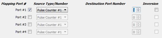
- To activate this function, simply check the box next to the selected port.

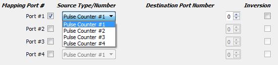
- Next, you must select the counter number to which the sensor is connected. The number of the counter depends on the version of the controller, so please refer to the controller documentation for the correct definition of the counter number.
- Next, select the virtual channel number of the ADC, in which the counter value will be placed in the register. Virtual channels begin their numbering right after the numbers of real ADC channels. Ie if you have on the controller for example four channels of ADC (ADC0, APC1, APC2, APC3), then the first channel number will be ATSTS5 and you accordingly need to select channel number 5.
- Setting channel number 5 of the ADC
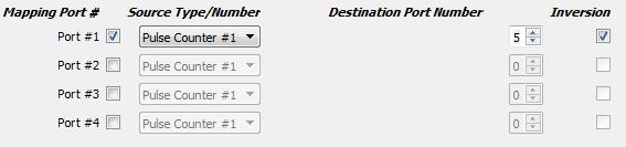
- If it is necessary to invert the value of the sensor, simply check the check box for the desired inversion.Inversion can be useful if, for example, the value from the sensor increases as the distance decreases, but it is necessary that the value of the sensor decreases when the distance is changed.
Example task: For example, we have an inductive sensor with an impulse frequency output.
As you approach the measurement object, the frequency from the sensor increases,
and when you move away from the object, the frequency decreases.
We have an ET1 controller with (four real inputs of the ADC and two inputs for the counter).
Our task is to adjust the height tracking while working on this sensor.
- Decision:
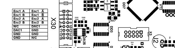
- Connect the sensor to the input of the counter 1. For this, the inputs ENC1 A and ENC Ā are used.
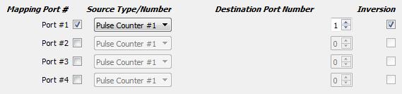
- Activate channel 1 in the settings menu of the ADC mapping. Select number of counter # 1.
- Since we are connected to the inputs of counter 1, the counter 1 is selected in the menu.
- Since there are four real ADCs on the controller, the first virtual channel will be channel 5 of the ADC. We choose him for work.
- For tracking, it is more convenient if the value of the ADC register increases with increasing distance to the object, and decreases when you approach the object. Our sensor works the other way around. Therefore, set the inversion on the selected port.
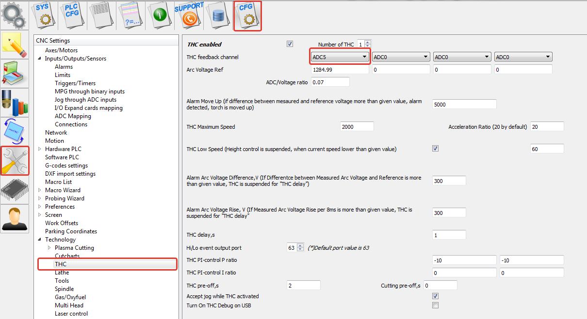
- Next, we will configure the gap stabilization system to work with the ADC5 channel, in the corresponding menu.
mycnc/adc_mapping.txt · Last modified: by pupalaiser