Table of Contents
myCNC-ET15 CNC controller
Currently, two breakout boards are available for the myCNC-ET15 controller:
1) ET10/ET15 board (comes with the ET10R5C controller model)
2) Full dedicated ET15 breakout board
Depending on the breakout board, the ET15 controller will have a different number of I/O ports. Please consult the chart below to find out the necessary model for your setup.
| Specs | Model 1 | Model 2 |
|---|---|---|
| Motor outputs | 6 | 8 |
| Pulse-dir | 6 channels, up to 3MHz | 8 channels, up to 3MHz |
| Analog -10V…+10V outputs | 6 channels | 8 channels |
| Galvanic isolated inputs | 48 | 64 |
| Encoder inputs | 4+2 channels | 8 channels |
| Closed loop motion control | (Pulse/Dir+Encoders) | (Pulse/Dir+Encoders) |
| Outputs (total) | 28 | 64 |
| Outputs (open collector) | 24 | 56 |
| PWM outputs | 4 | 8 |
| RS485 Modbus | yes | yes |
NOTE: The above information is subject to change.
Power supply connection
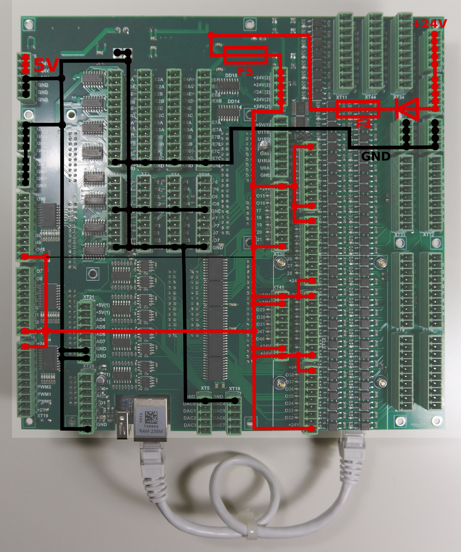
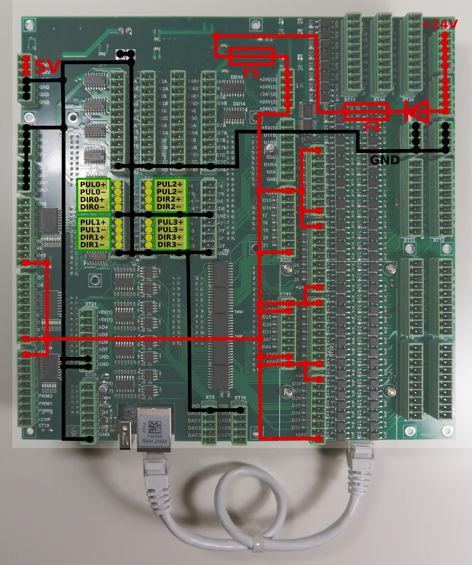
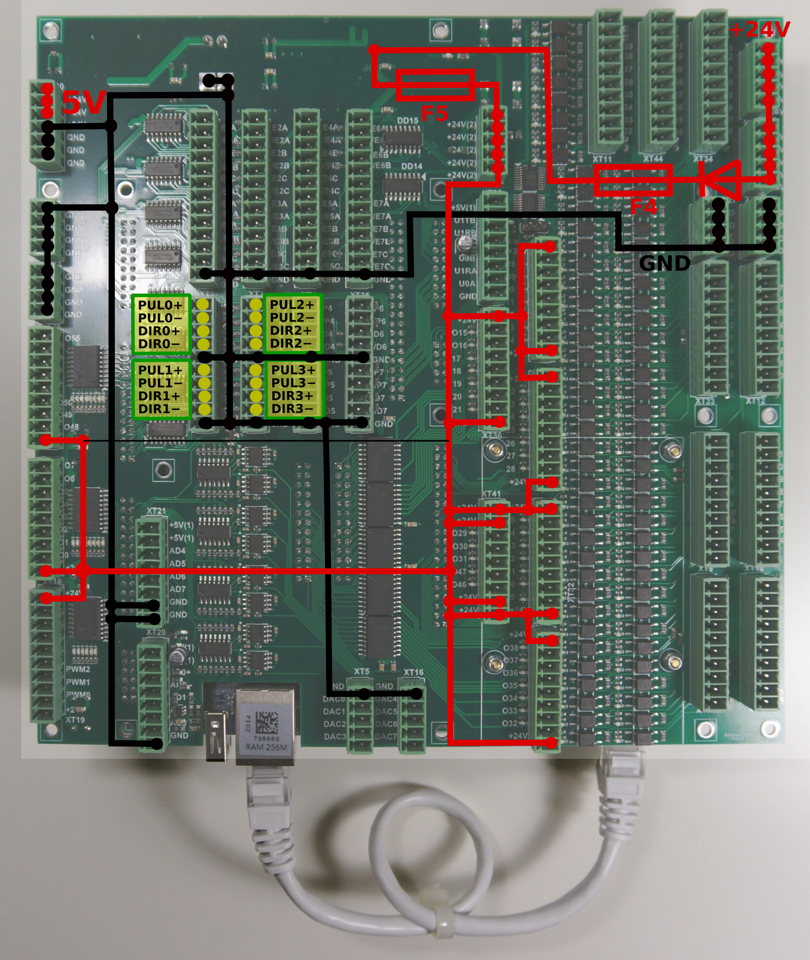
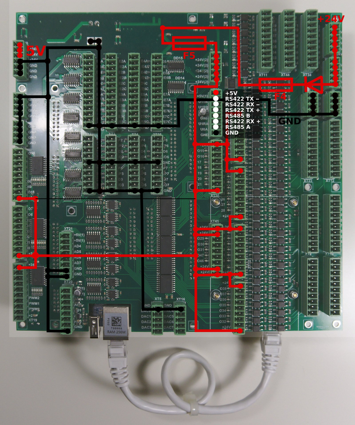
myCNC-ET15 control board uses 24VDC . The board contains 4 pins for connection +24V (joined internally) and a number of GND pins for convenient connection of external devices. Power Supply 24V DC and +24V and GND pins are shown in a picture below.
NOTE: The board has a set of incorrectly labelled 5V pins (labelled on the board as 24V). Below is the correct power supply pinout:
Pulse-Dir outputs
ET15 has 8 channel pulse/dir outputs, 3MHz max pulses frequency.
ET15 pulse dir outputs conform RS422 standard and compatible with most of servo and stepper drivers (line driver with paraphase signals positive and negative polarity). Internal schematic for pulse-dir is shown in a picture below.
ET15 Output pins
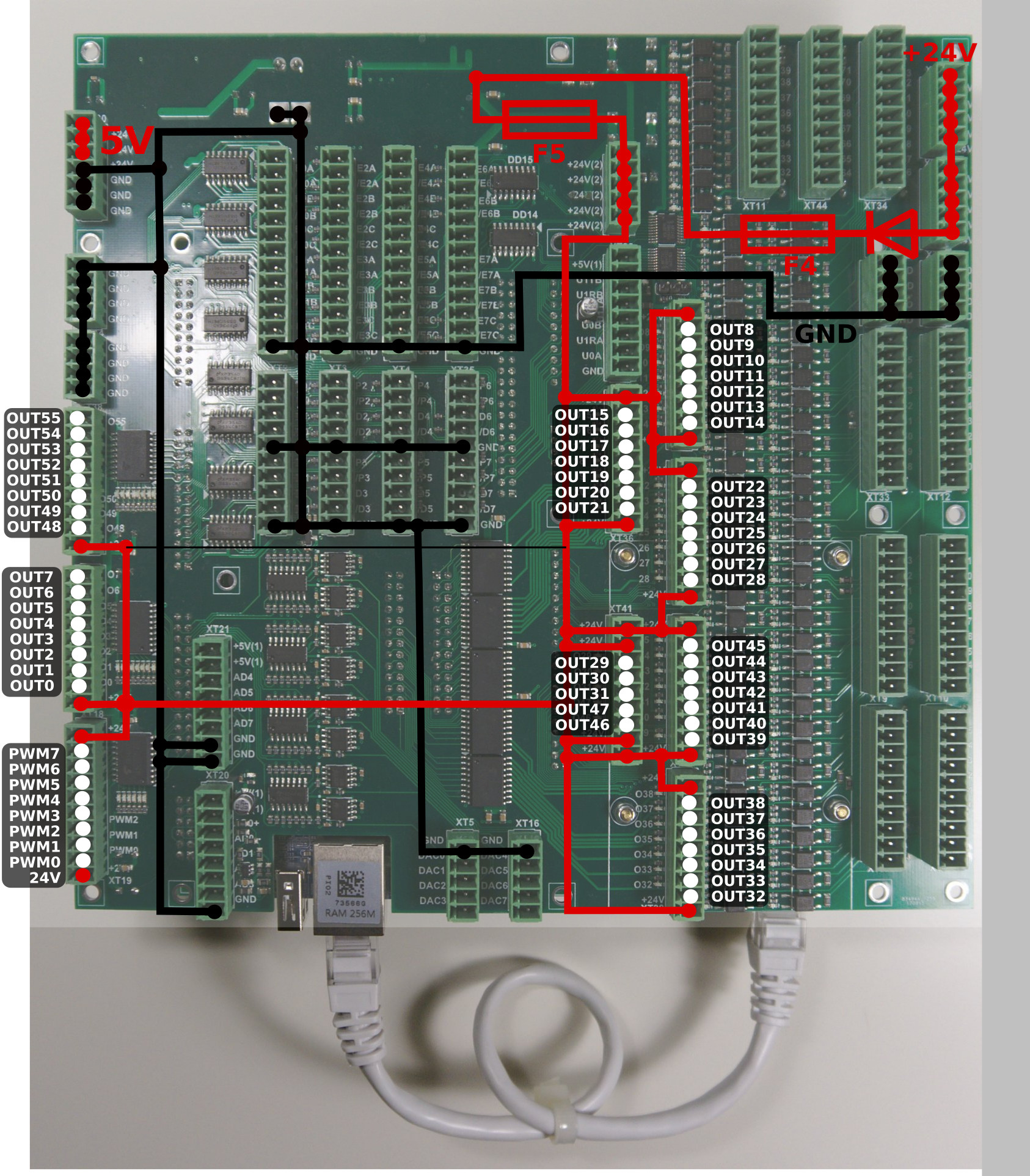
ET15 board contains 64 output pins-
- 56 open collector outputs (OUT#0-OUT#55)
- 8 PWM outputs (PWM#0 - PWM#7)
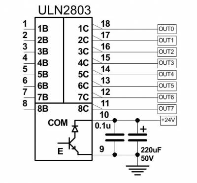
An internal schematic is shown in the picture below. Darlington transistors array chip ULN2803 is used to buffer binary outputs in ET15. Each chip contains 8 transistors and handles 8 binary outputs.
ET15 pinout for outputs is shown below
Galvanic isolated inputs
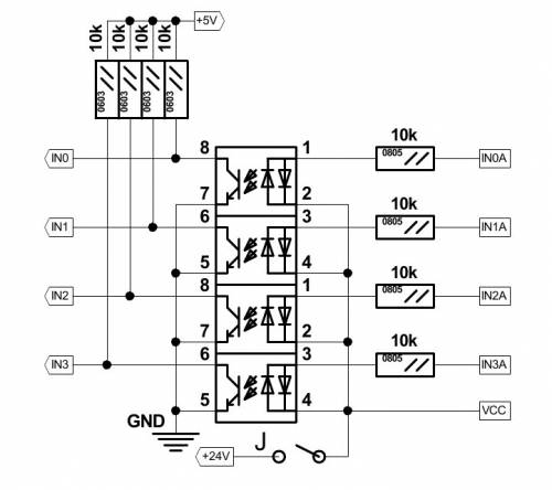
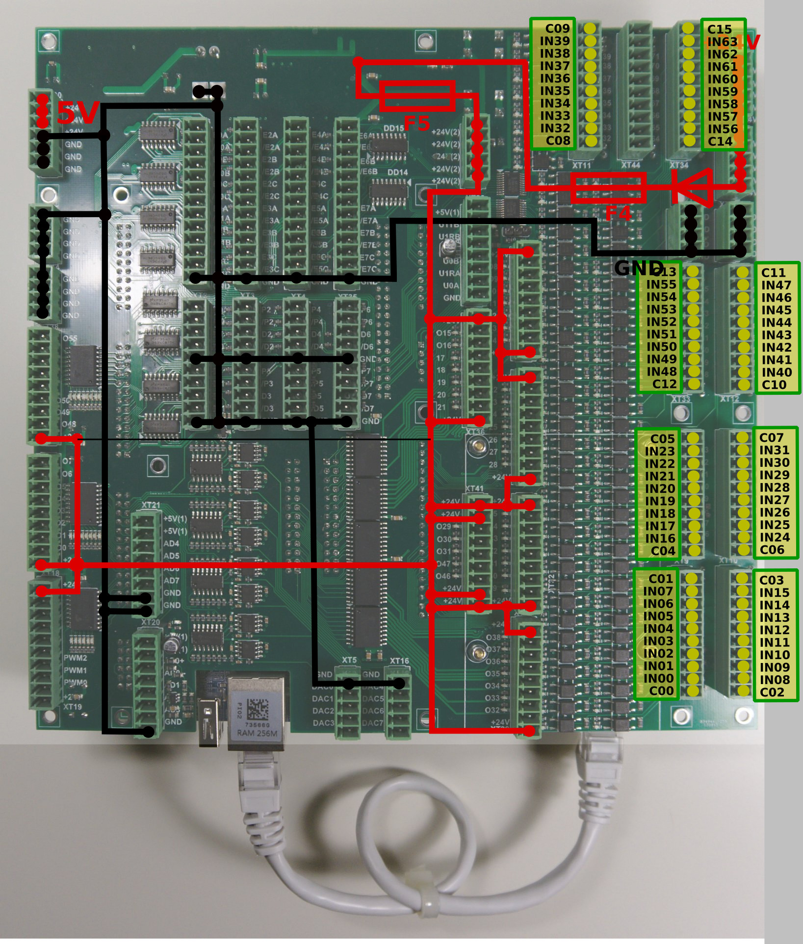
The ET15 control board has 64+8 galvanic isolated binary inputs, 16+2 groups of 4 inputs each. Each group has separate power supply pins so inputs can be powered from different power sources. Using PNP and NPN sensors simultaneously is possible too. Schematic of 4 inputs group is shown in a picture below.
16 groups (64 pins total) are independent inputs.
Additional 2 groups (8 optocoupler inputs) are connected to 8 encoder inputs pins (ENCODER pins 5B, 5C, 6A, 6B,6C, 7A, 7B, 7C). Change SW1 position to select either galvanic isolated inputs or line driver inputs for INPUTS #64…#71.
ET15 Encoder inputs
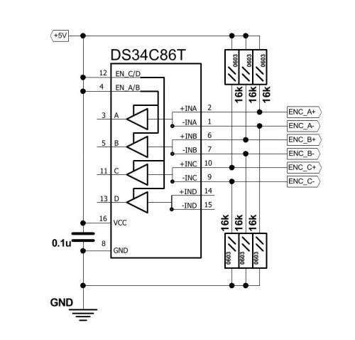
ET15 board has 8 Incremental encoder inputs. ET15 encoder inputs conform RS422 standard and compatible with most of the servo drivers and line driver incremental encoders. 34C86 chip is used in ET15 as a receiver of encoder signals. Internal schematic for line driver encoder inputs is shown on a picture below.
INCREMENTAL ENCODER inputs schematic (1 Encoder, ABC signals is shown)
ENCODERS channels 0,1,2,3 pinout
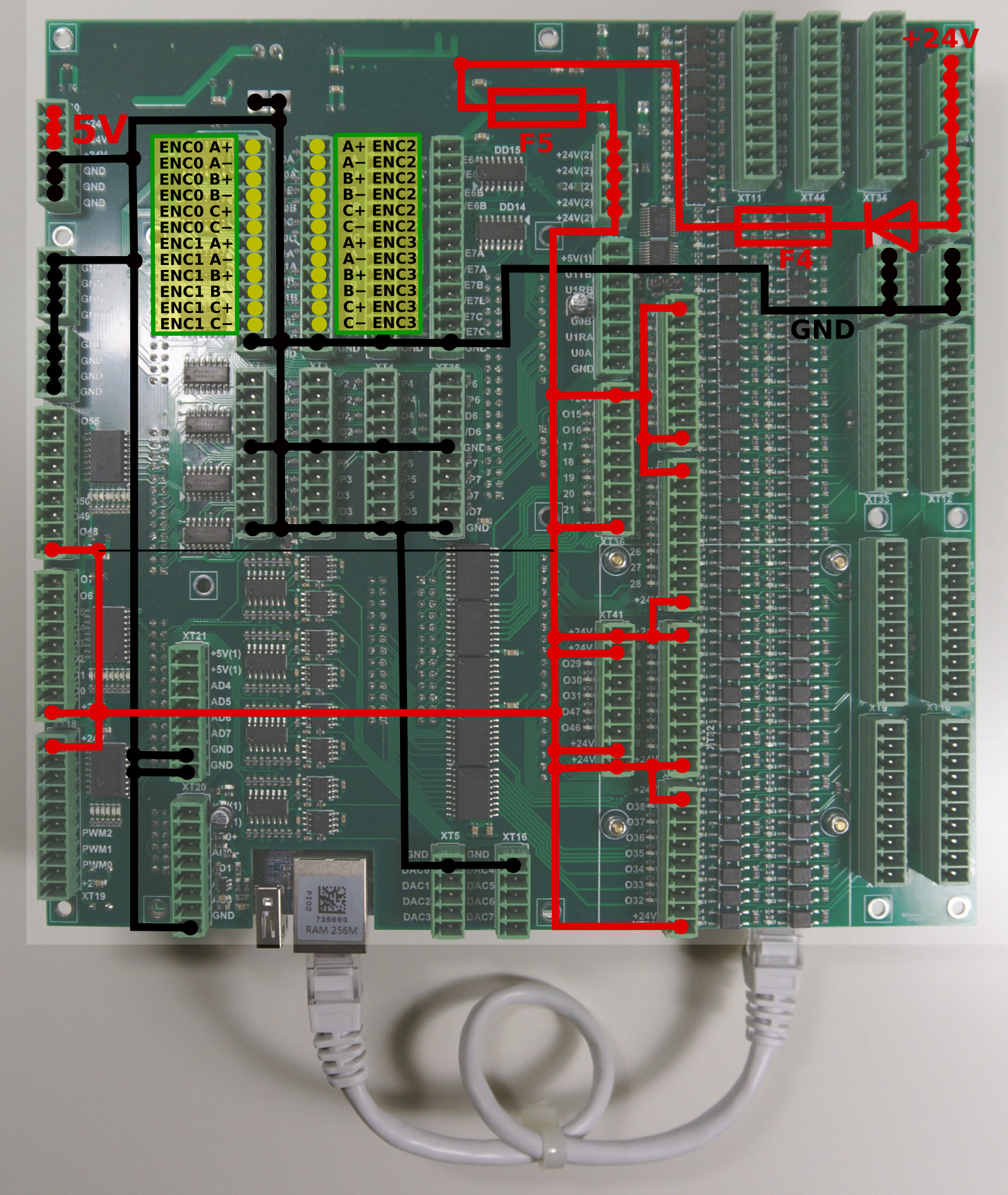
ENCODERS channels 4,5,6,7 pinout
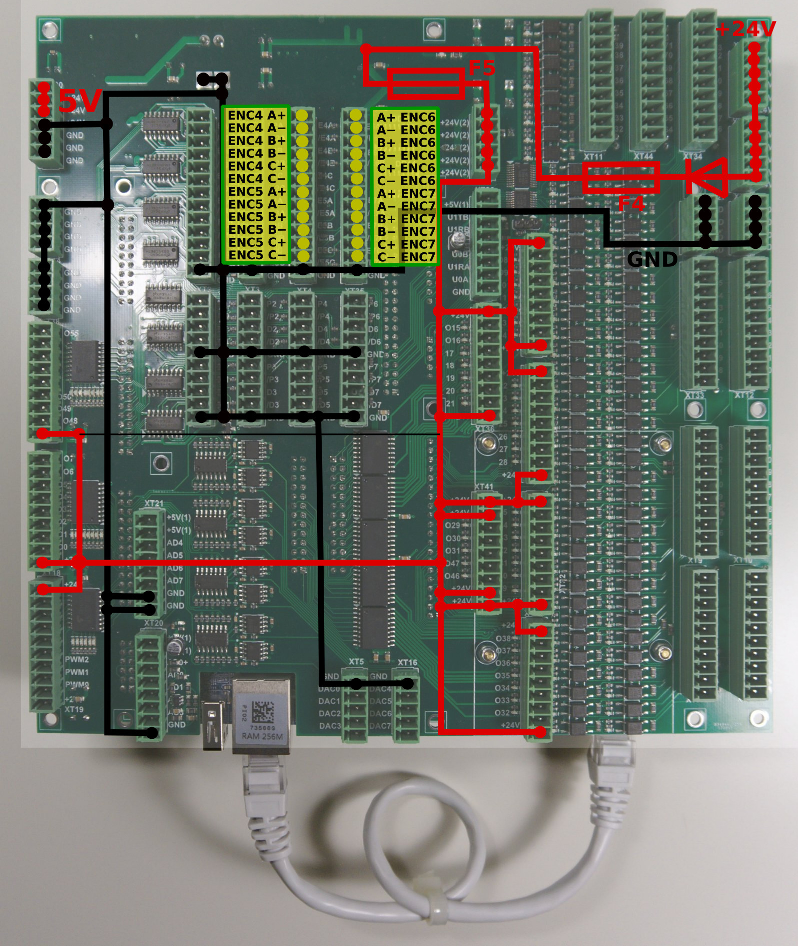
Encoder inputs are mapped to general-purpose inputs space, addresses from 64 to 87. ET15 board can use up to 88 binary inputs in total.
ADC Inputs
myCNC-ET15 Control board has 8 ADC inputs 0…5V Range. ADC inputs connectors have also GND and +5V DC output pins for convenient potentiometer connection. The picture below shows an example of potentiometer connected to ADC2 input.
RS422/RS485 Bus
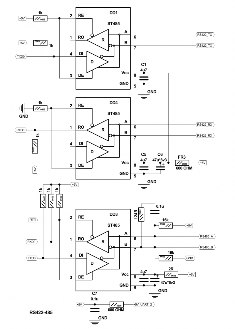
RS422 and RS485 bus interfaces are implemented in the hardware of myCNC-ET15 control board. Software level includes Modbus ASCII/RTU and Hypertherm Serial communication interfaces for both RS485 and RS422.
Output schematics of RS422, RS485 interfaces are shown below
A myCNC-ET15 control board has RS422/RS485 bus connector. Connector pinout for RS422, RS485 shown below
Connection Examples
3-wire NPN sensor connection example
3-wire PNP sensor connection example
Switch connection example
Jumper for selected group (one of J1,J2,J3,J4) is closed.
Common wire for 4 optocoupler units is connected to internal +24V if Jumper is closed. A switch should short another optocoupler input to GND(0V) to activate input pin.
J4 should be closed to connect the optocoupler pin to +24V. A switch should short wire to GND(0V).
Spindle Speed control over DAC (0-10V) output
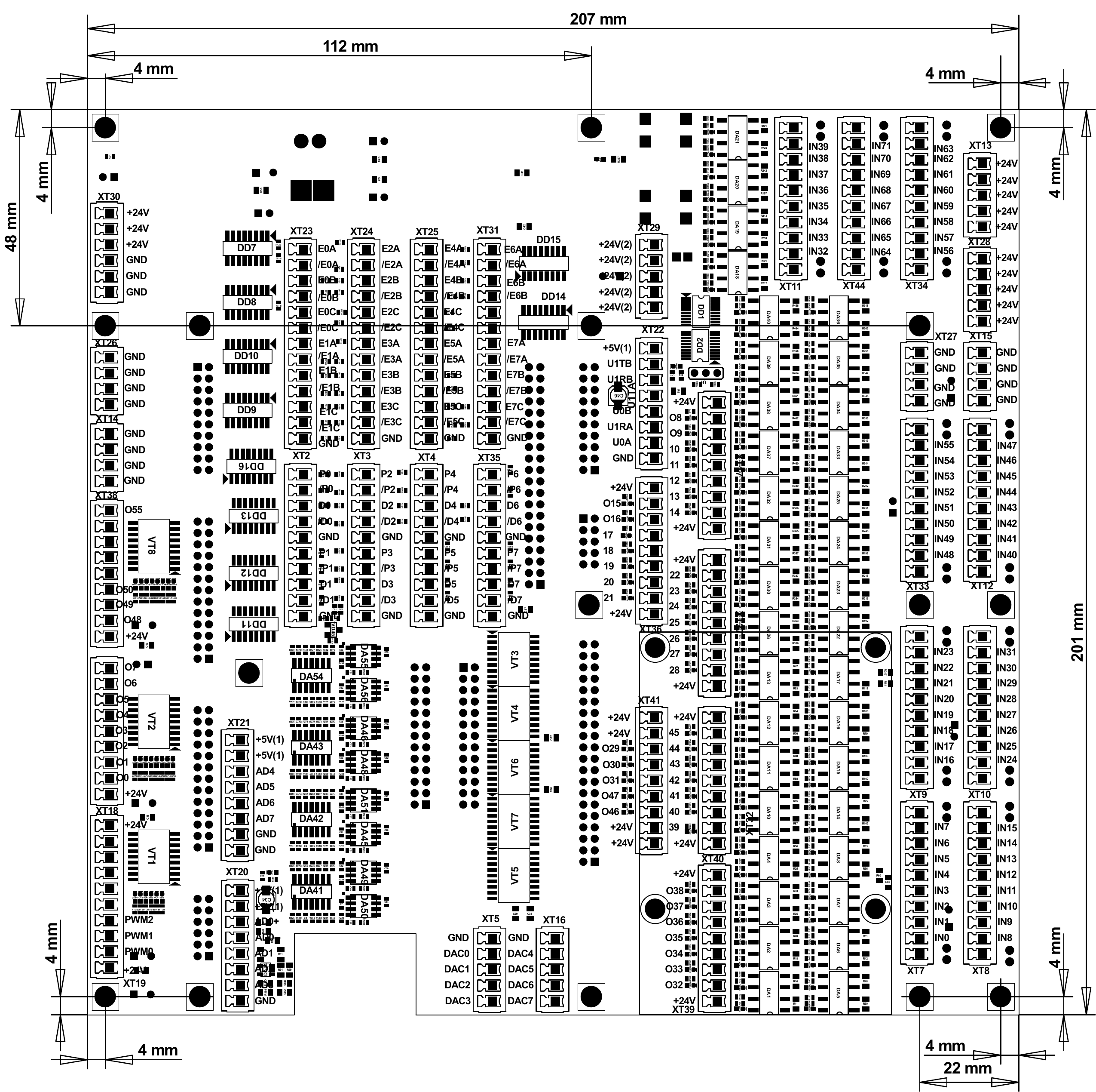
Board dimension
SSH access to ET15
ET15 board firmware based on RT-Linux and have SSH server installed and configured to get access to the board, configure it, modify and update the firmware.
Data to access:
| SSH port | 22 |
| login | mycnc |
| password | operator |
| command to access | ssh mycnc@192.168.0.69 |
| command to access | ssh mycnc@192.168.4.69 |
Axes kinematics for ET15
ET15 board firmware supports user-defined kinematics transformation.
ET15 firmware runs procedure MKinematics every servo loop. The procedure gets pointers to input and output coordinate arrays. MKinematics procedure definition is
void MKinematics(int64_t * input, int64_t * output, uint32_t naxes);
It's supposed the procedure fills output coordinates array according to machine kinematics. MKinematics procedure may contain simple assignment outputs coordinates to input values accordingly if no need in kinematics transformations.
void KinematicsPlugin::MKinematics(int64_t *input, int64_t *output, uint32_t naxes)
{
    for (uint32_t i=0;i<naxes;i++) output[i]=input[i];
    return;
}
Another way to disable kinematics plugin completely is removing plugin library file libkinematicsplugin.so from the plugins folder.
Example for MKinematics procedure for robot kinematics is show below
void KinematicsPlugin::MKinematics(int64_t *input, int64_t *output, uint32_t naxes)
{

    double x=input[0]*InputRatio[0];
    double y=input[1]*InputRatio[1];
    double z=input[2]*InputRatio[2];

    double M2=x*x+y*y;
    double M=sqrt(M2);
    double L2=M2+z*z;
    double L=sqrt(L2);

    double a=acos(x/M);
    double b=asin(z/L);
    double d=acos((R1*R1+R2*R2-L2)/(2*R1*R2));
    double f=asin(sin(d)*R2/L);
    double c=b+f;

    output[0]=a*OutputRatio[0];
    output[1]=c*OutputRatio[1];
    output[2]=d*OutputRatio[2];

}
MKinematics procedure is a part of complete C++ class MKinematicsPlugin which may have other variables and functions beside of the main MKinematics.
For example, MKinematics uses variables R1, R2 which are joints length. The variable values can be defines statically in the class constructor
KinematicsPlugin::KinematicsPlugin(QObject *parent) :
    QObject(parent)
{
    for (int i=0;i<32;i++)
    {
        InputRatio[i]=1;
        OutputRatio[i]=1;
    }
    R1=100;
    R2=50;
}
or assigned from the main firmware code by running setParameters procedure which is a part of the plugin interface
void KinematicsPlugin::setParameters(uint32_t addr, double param)
{
    switch (addr)
    {
    case 0: R1=param;break;
    case 1: R2=param;break;
    }
}
myCNC controller software uses 64 bits fixed point values and operates “units” which are equal to “pulse” (for pulse-dir motor drivers) or “encoder unit” for analogue servo control.
To calculate kinematics formulas the values should be in real units like a millimetre, inch, degree or radian.
Ratios to translate “pulses” to “millimetres” or “radians” before kinematics translation can be either assigned statically or received from the main software through interface procedure setInputRatios
void KinematicsPlugin::setInputRatios(double * ratio, uint32_t naxes)
{
    for (uint32_t i=0;i<naxes;i++) InputRatio[i]=ratio[i];
}
After kinematics translations coordinate values should be translated back to “pulse” units. It can be made by rnning setOutputRatios procedure or assigned statically in the plugin code.
void KinematicsPlugin::setOutputRatios(double * ratio, uint32_t naxes)
{
    for (uint32_t i=0;i<naxes;i++) OutputRatio[i]=ratio[i];
}
Kinematics plugin is in R&D stage. We may change this interface later.
A complete example of the kinematics plugin is -
Kinematics plugin source file
- kinematicsplugin.cpp
#include "kinematicsplugin.h"
#include <math.h>
KinematicsPlugin::KinematicsPlugin(QObject *parent) : QObject(parent)
{
    for (int i=0;i<32;i++)
    {
        InputRatio[i]=1;
        OutputRatio[i]=1;
    }
    R1=100;
    R2=50;
}

void KinematicsPlugin::setParameters(uint32_t addr, double param)
{
    switch (addr)
    {
    case 0: R1=param;break;
    case 1: R2=param;break;
    }
}

void KinematicsPlugin::MKinematics(int64_t *input, int64_t *output, uint32_t naxes)
{
    for (uint32_t i=0;i<naxes;i++) output[i]=input[i];

//    for (uint32_t i=0;i<naxes;i++) output[i]=input[0]/(i+1);
    return;

    for (uint32_t i=0;i<naxes;i++) output[i]=input[i]*InputRatio[i]*OutputRatio[i];

    double x=input[0]*InputRatio[0];
    double y=input[1]*InputRatio[1];
    double z=input[2]*InputRatio[2];

    double M2=x*x+y*y;
    double M=sqrt(M2);
    double L2=M2+z*z;
    double L=sqrt(L2);

    double a=acos(x/M);
    double b=asin(z/L);
    double d=acos((R1*R1+R2*R2-L2)/(2*R1*R2));
    double f=asin(sin(d)*R2/L);
    double c=b+f;

    output[0]=a*OutputRatio[0];
    output[1]=c*OutputRatio[1];
    output[2]=d*OutputRatio[2];

}


void KinematicsPlugin::setInputRatios(double * ratio, uint32_t naxes)
{
    for (uint32_t i=0;i<naxes;i++) InputRatio[i]=ratio[i];
}

void KinematicsPlugin::setOutputRatios(double * ratio, uint32_t naxes)
{
    for (uint32_t i=0;i<naxes;i++) OutputRatio[i]=ratio[i];
}
Kinematics plugin include file
- kinematicsplugin.h
#ifndef KINEMATICSPLUGIN_H
#define KINEMATICSPLUGIN_H
#include "kinematicsinterface.h"
#include <QObject>
#include <QtPlugin>
class KinematicsPlugin : public QObject, KinematicsInterface
{
    Q_OBJECT
    Q_PLUGIN_METADATA(IID Kinematics_Interface_iid FILE "kinematicsplugin.json")
    Q_INTERFACES(KinematicsInterface)
public:
    KinematicsPlugin(QObject *parent = 0);
    void MKinematics(int64_t * input, int64_t * output, uint32_t naxes);
    void setInputRatios(double * ratio, uint32_t naxes);
    void setOutputRatios(double * ratio, uint32_t naxes);
    void setParameters(uint32_t addr, double param);
protected:
    double InputRatio[32];
    double OutputRatio[32];
    double R1,R2;
};
#endif // KINEMATICSPLUGIN_H
Kinematics plugin interface include file
- kinematicsplugininterface.h
ifndef KINEMATICSINTERFACE_H
#define KINEMATICSINTERFACE_H
#include <stdint.h>
#include <QtPlugin>
class KinematicsInterface
{
public:
    virtual ~KinematicsInterface() {}
    virtual void MKinematics(int64_t * input, int64_t * output, uint32_t naxes) = 0;
    virtual void setInputRatios(double * ratio, uint32_t naxes) = 0;
    virtual void setOutputRatios(double * ratio, uint32_t naxes) = 0;
    virtual void setParameters(uint32_t addr, double param) = 0;
};

#define Kinematics_Interface_iid "pv-automation.myCNC.ET15.R1.KinematicsInterface"
Q_DECLARE_INTERFACE(KinematicsInterface, Kinematics_Interface_iid)
#endif // KINEMATICSINTERFACE_H
A complete sources archive for this kinematiics plugin example can be downloaded here-
http://pv-automation.com/downloads/kinematics_2018-0205_0000.tar.bz2 http://cnc42.com/downloads/1366.7z

