Table of Contents
CNC Vision (Optical Registration Mark Reading) Setup
This manual is designed to introduce the reader to the setup process of the CNC Vision system, and some of its applications which include the creation of a Digitally Aligned Cutting System.
The CNC Vision System is often used in the X1366V Tangential Cutting profile. The description of the X1366V GUI is available here: Basic profile for Tangential Knife.
Please note that the Vision System license for correcting the generated G-code using registration mark reading is a separate license that must be purchased in addition to the myCNC controller in order for the DACS (Digitally Aligned Cutting System) to be enabled (available as part of the CNC Vision Kit package in our Online Shop).
NOTE: The CNC Vision functionality is currently supported on Linux systems ONLY.
A video with the recap of the manual below is available here:
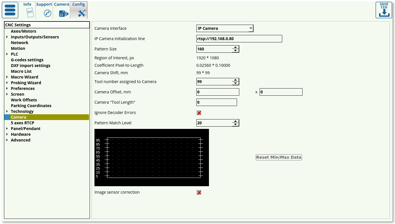
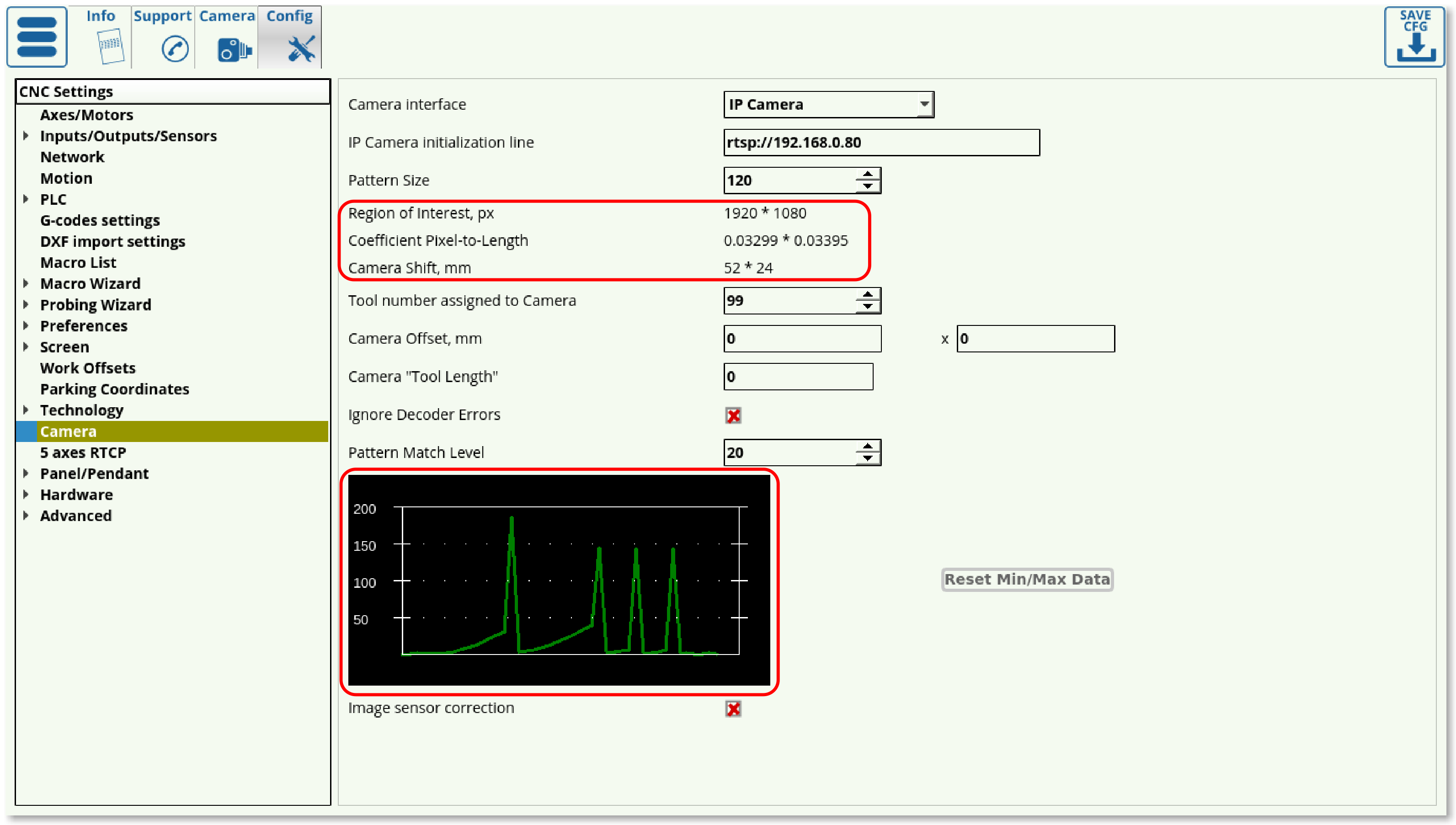
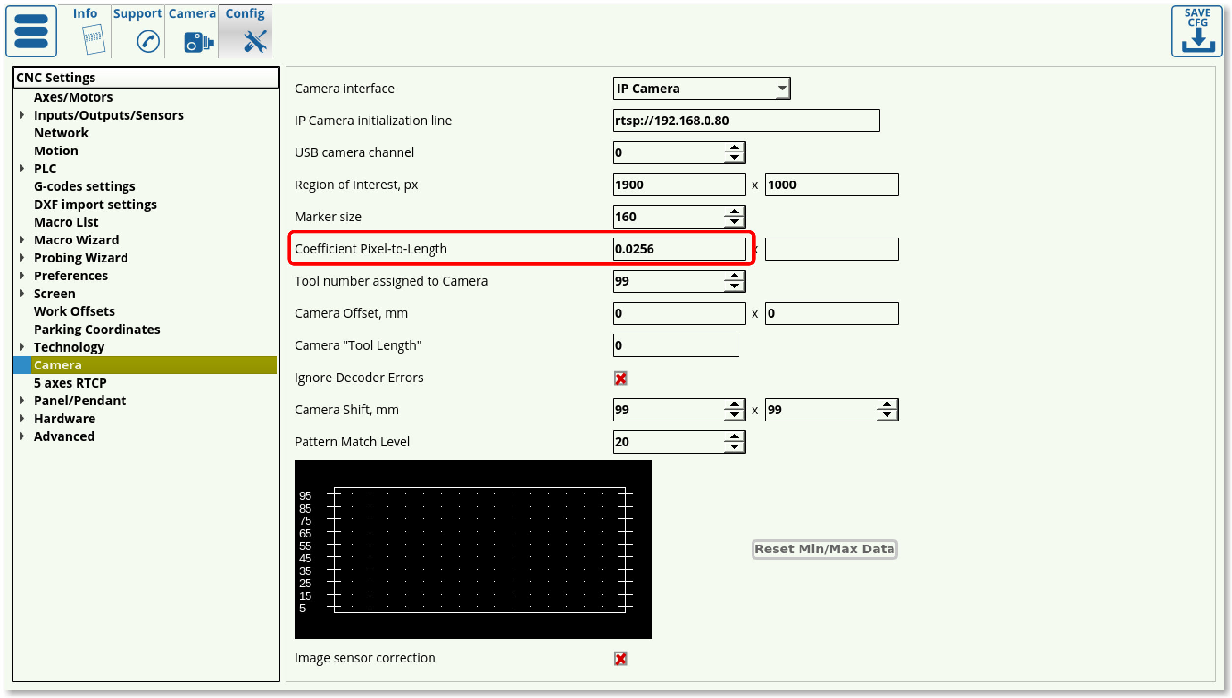
In order to set up the camera, you must go into the CNC Settings > Config > Camera. The screen presented to you will be the one shown below:
- Camera Interface allows to choose No Camera and a camera that is connected through LAN. If the camera is connected through LAN, the Initialization line must list the correct IP address of the camera.
- IP Camera Initialization line lists the camera IP for the connection to be established.
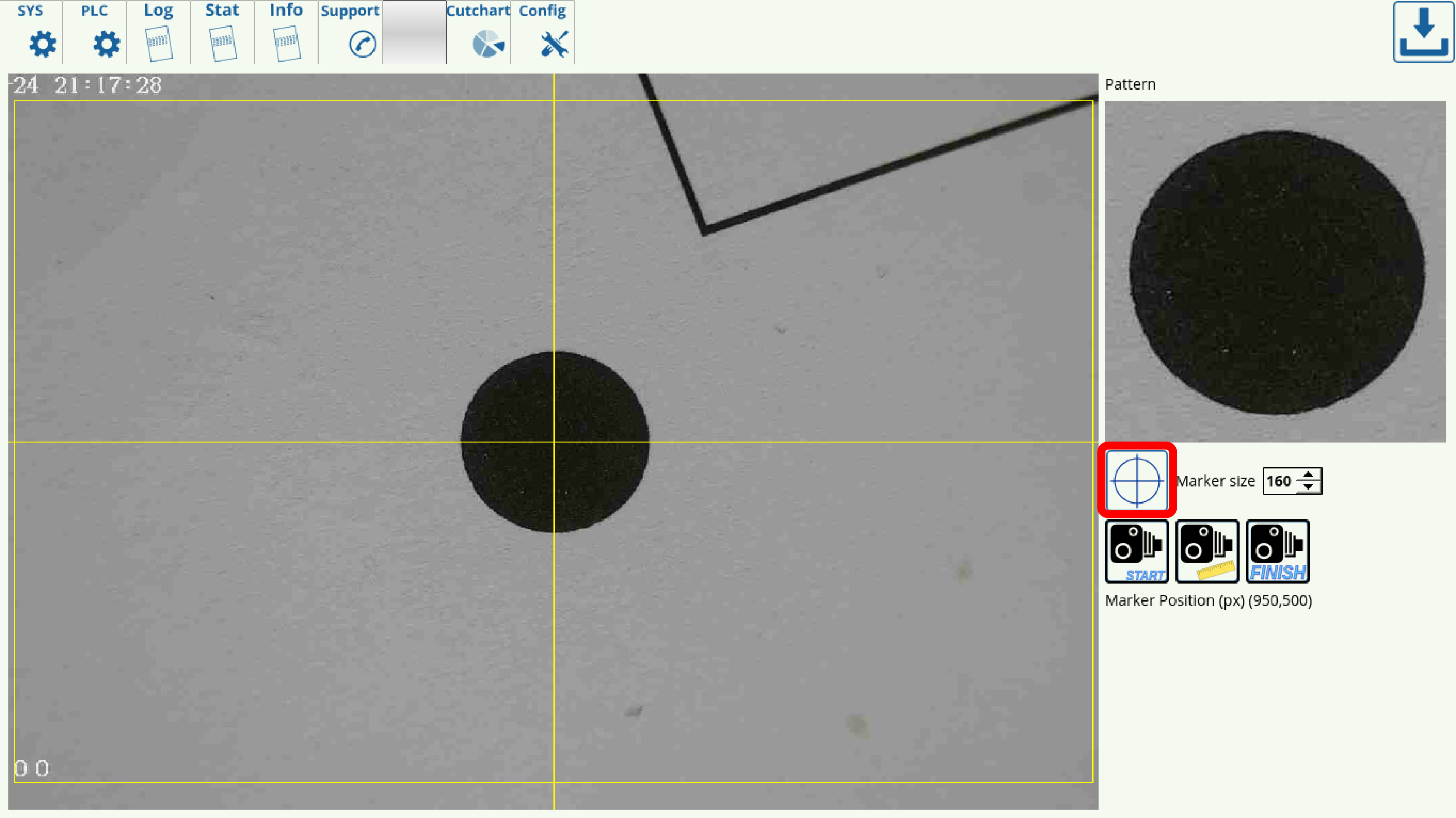
- Pattern size can be set experimentally to be about 30-50% larger than the registration mark itself, in order to account for the visual transition between the registration marker and its surroundings.
- In the case of the particular registration marker used in this scenario, its size has been set to 160 pixels, which is on the low end of the relative pattern size - a larger pattern size is typically a safer choice in low-light conditions.
- NOTE: The camera focus must be properly adjusted in order for the camera to recognize markers.
- Region of interest (in pixels) signifies the area in which the camera is actively looking for registration marks, and should usually be set to be equal or slightly smaller than the actual resolution of the camera. It is set automatically in the newer software versions during the calibration process (software versions after July 2019).
- Pixel to length coefficient is used to convert the pixels travelled into the actual physical distance moved, in mm. You are able to calibrate this for both the x- and the y-axes. In order to set up the correct coefficient for your camera, use the Calibrate button in the Camera tab, or consult the full set of manual set up instructions below (useful for older software versions).
- Camera Shift describes the distance the machine will move by if it does not locate a registration marker after it has been instructed to look for one. This can happen when the marker is not fully within the region of interest. In that case, the camera will keep on moving around until it either finds the marker or reaches the end of this specified Camera Shift. It is set automatically in the newer software versions during the calibration process. If no registration marker is found during the Camera Shift process, the machine will be stopped.
- Tool number is typically assigned to be 10.
- Camera offset values are used to specify the distance from the camera to the working tool in the xy-plane.
- Camera tool length value is used to specify the distance from the camera to the working tool tip in the z-axis.
- Ignore decoder errors flag is set to OFF by default.
- Shift Speed describes the speed with which the machine is moving during its camera shift phase while trying to find the registration marker for the DACS. NOTE: Deprecated on the newer versions of myCNC software.
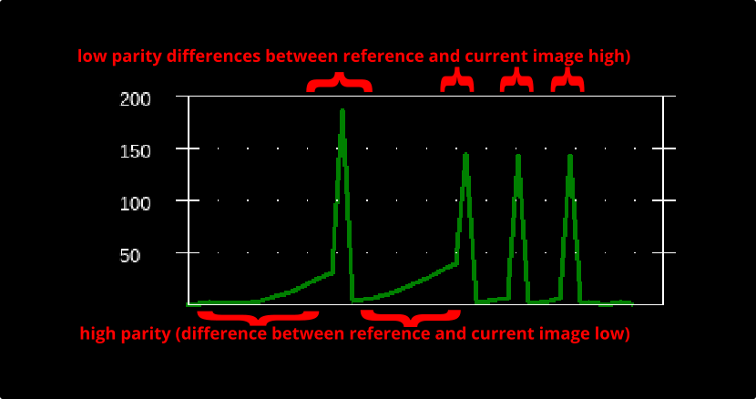
- Pattern Match Level describes the level of parity with the original reference registration marker that each new marker must have for the system to recognize it. Higher numbers mean less parity (more differences between the markers), so as to avoid false positives it is advised to keep the numbers on the lower end of the scale. The graph below the Pattern Match Level indicates the parity levels during the machine search for markers, with the low points of the graph being indicative of the places where marker parity is highest (differences between new marker and reference are lowest).
- If the program has issues locating markers due to those markers being slightly different (due to material imperfections, light reflections, etc), it is recommended to raise the Pattern Match Level until the program accepts the variations. However, raising this value too high will lead to false positives on marker recognition.
- Image sensor correction corrects for sensors with different aspect ratios. Use this if the registration mark image appears distorted or stretched when viewed through the Camera tab in myCNC software.
CNC Vision codes
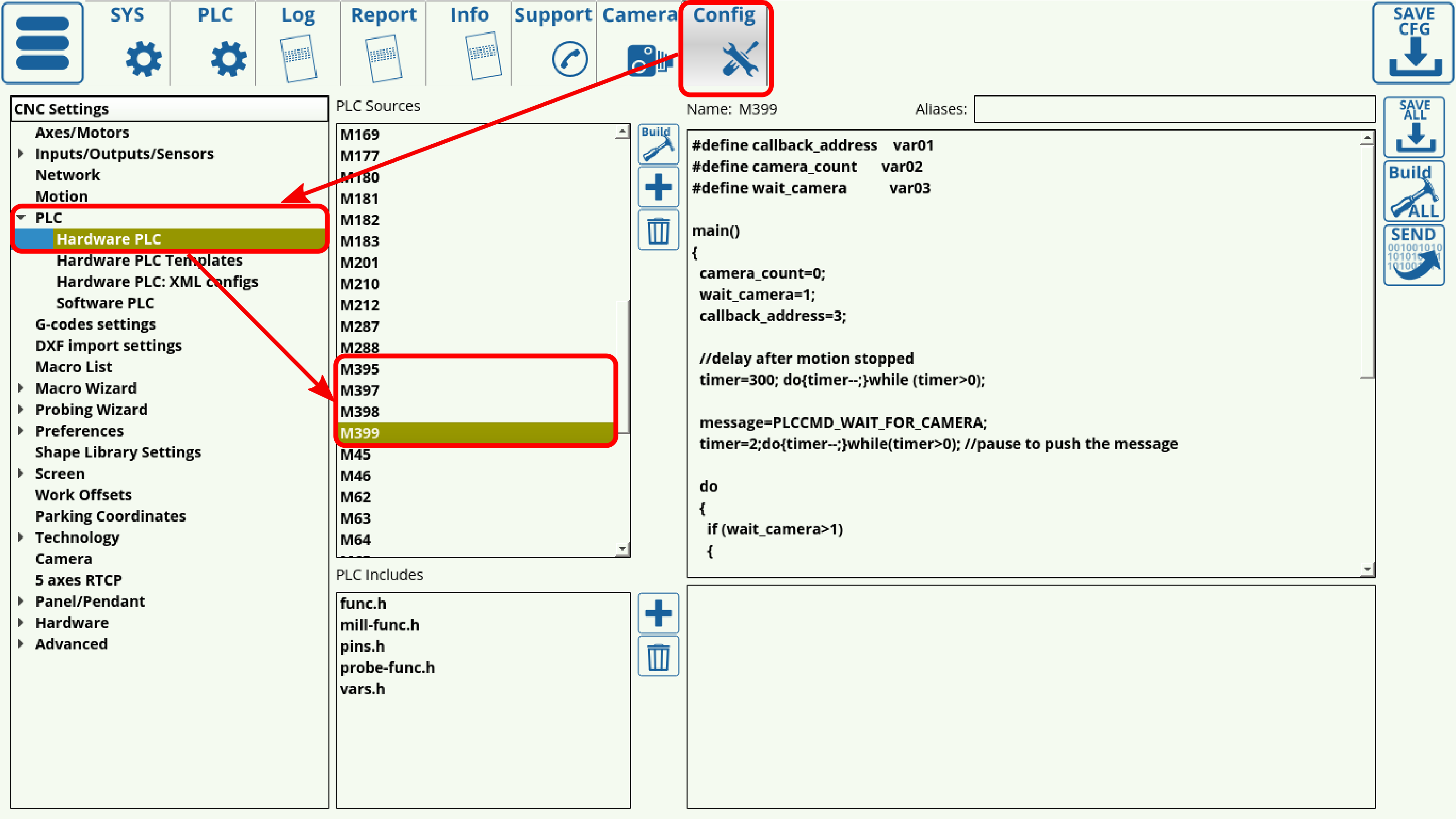
The Vision system is controlled through a series of M-code PLCs which can be found in Settings > Config > PLC > Hardware PLC.
The following PLC procedures are used:
- M395 - camera calibration. Show M395 code
- M397 - start camera operations. Show M397 code
- M399 - record the image, detect the marker position and store it in a dots array. Show M399 code
- M398 - calculate rotation, offset and distortion values and make a correction accordingly for the rest of the G-code file, then run the corrected G-code. Show M398 code
These PLCs are added automatically into the G-code when importing a DXF file into myCNC. In order for the system to recognize the markers, the markers need to be drawn as roughly 6mm circles inside a separate layer named Camera within the DXF file. The user must have a valid Vision System license to use this function.
Additionally, as all the camera operations are done through a simple combination of commands listed above, the user may choose to forego DXF import altogether. Instead, the movement to the coordinates of the marker (via G0) and the M399 command to search for markers, as well as М397 and М398 serving as header and footer for the necessary block of code, can be added directly via a CAM or a post processor at appropriate positions. This allows the user to utilize their preferred CAM software, which may often have additional functionality as compared to the standard DXF import bundled with myCNC.
Calibrating the CNC Vision System
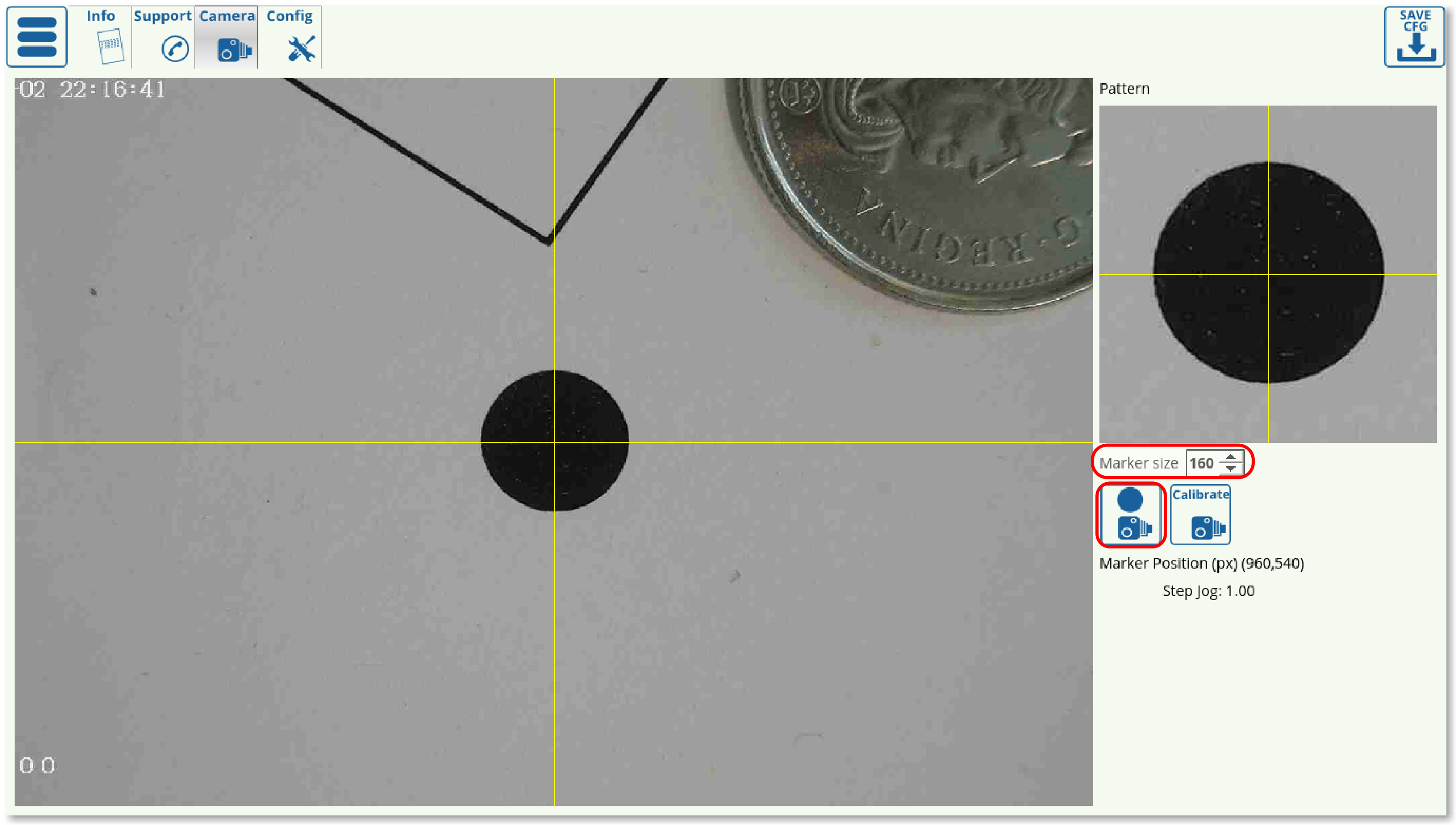
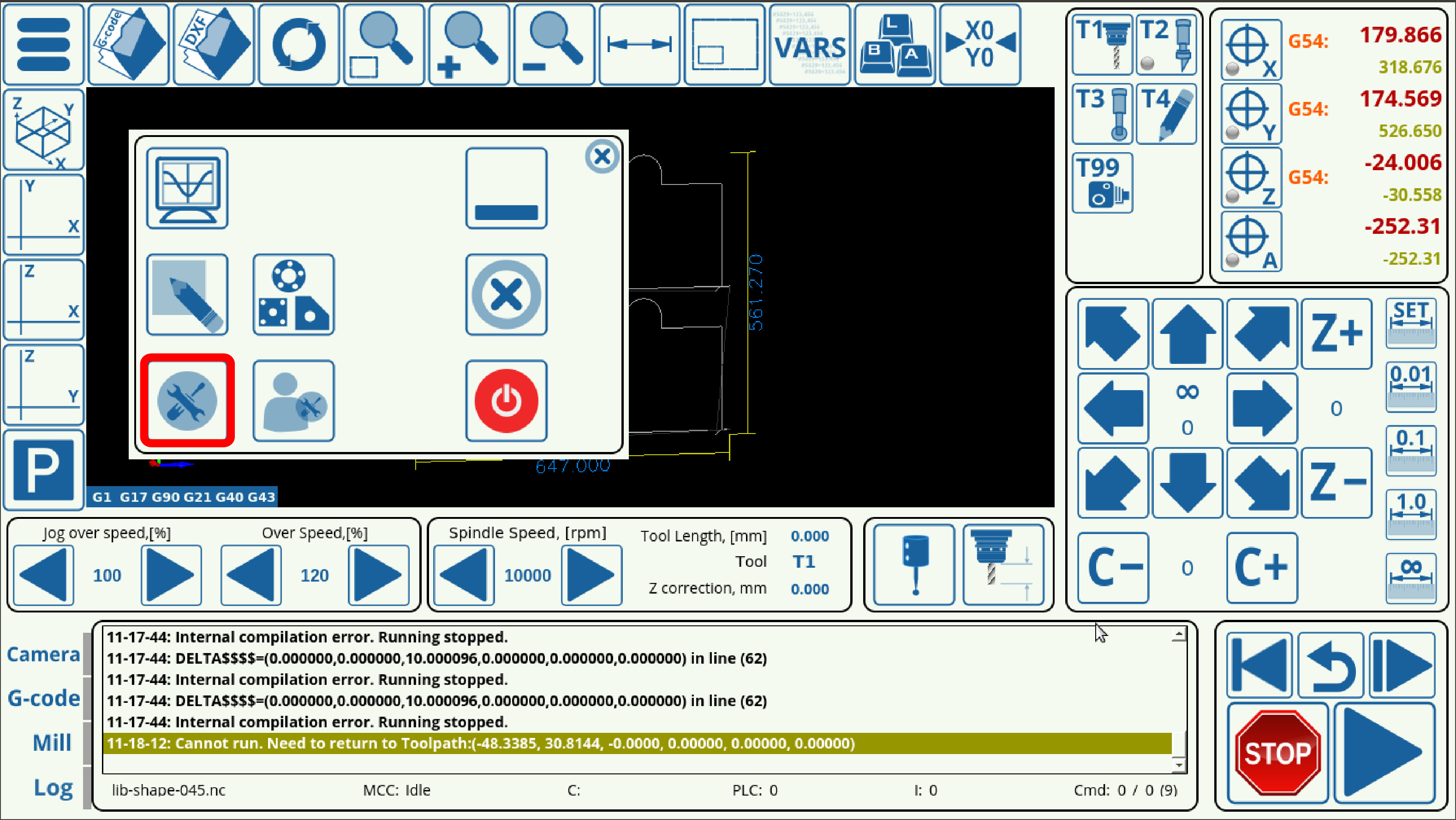
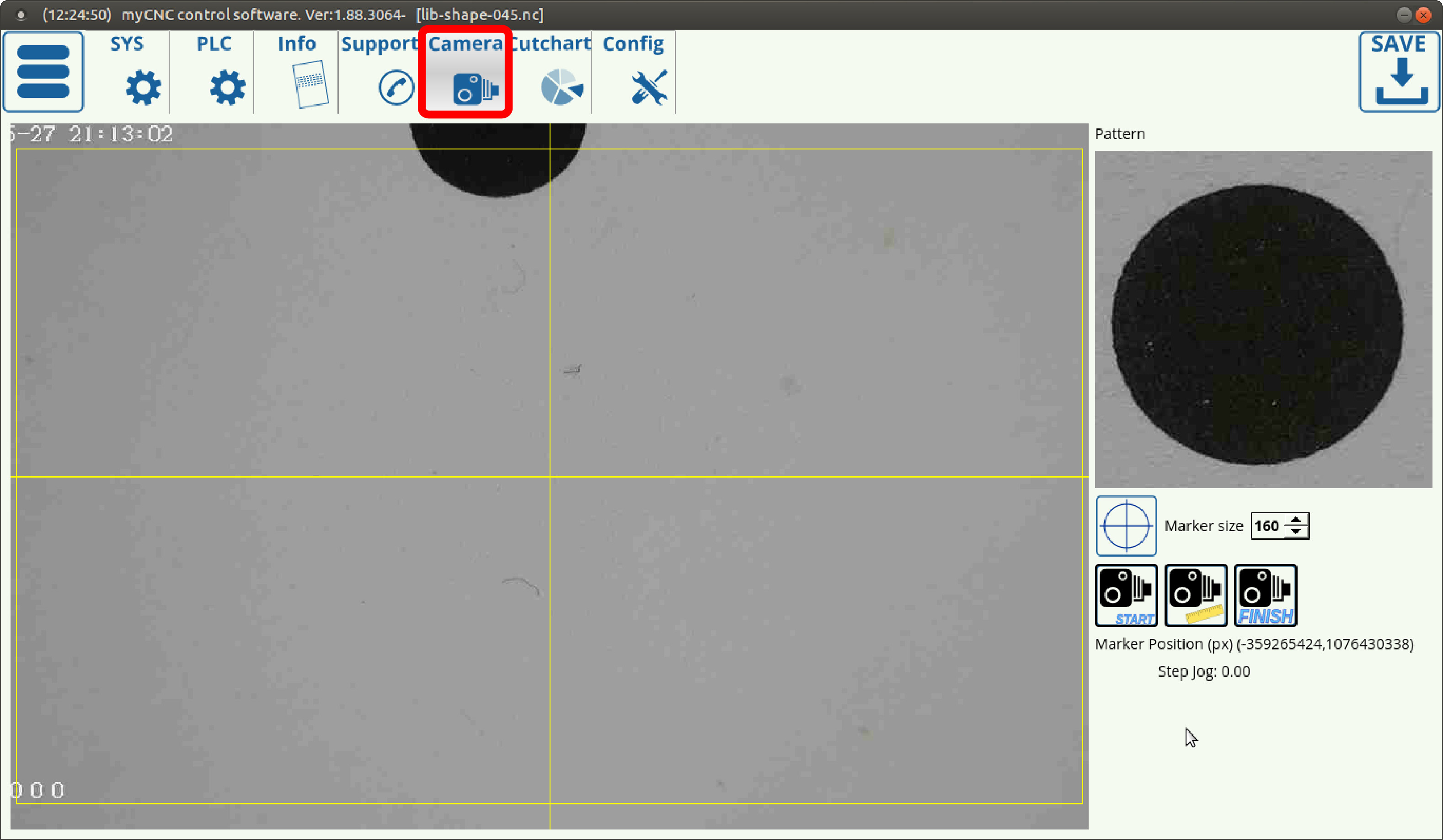
- Go to the Camera tab of myCNC software by opening the Settings panel from the main screen
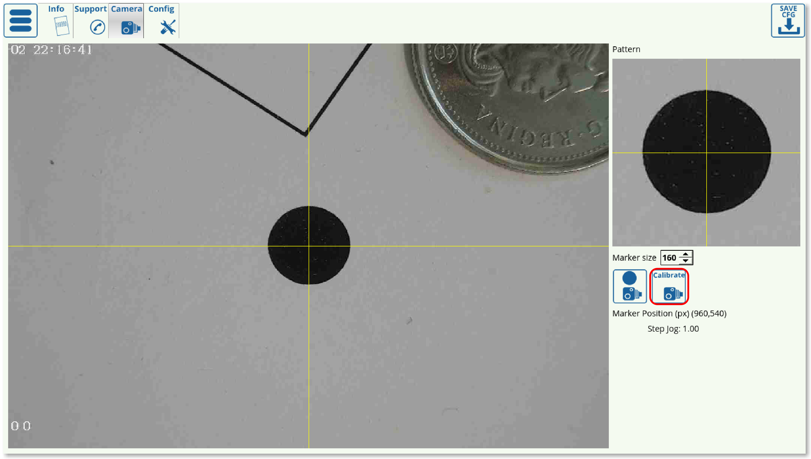
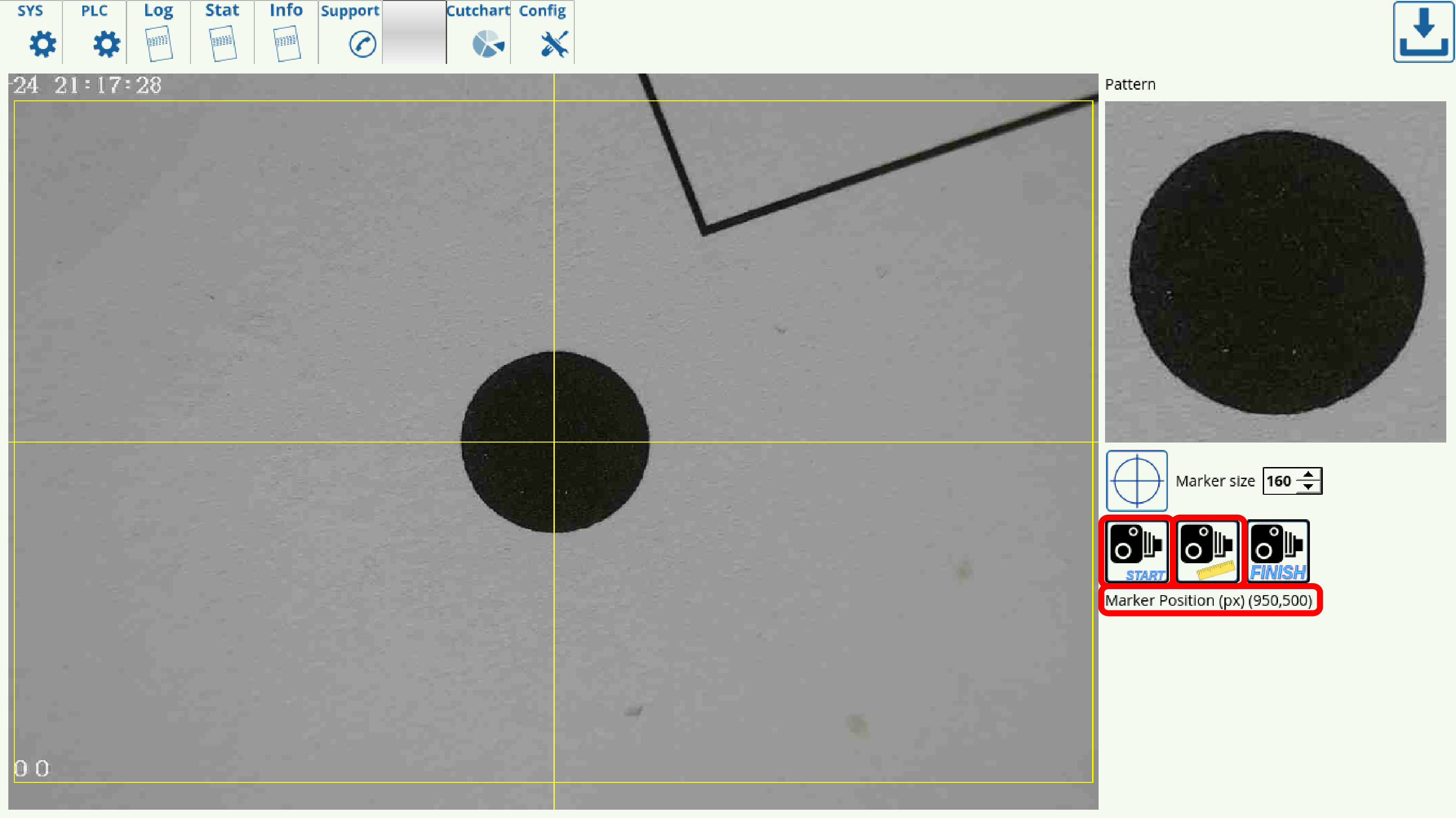
- Select an appropriate marker (pattern) size and click the Record button
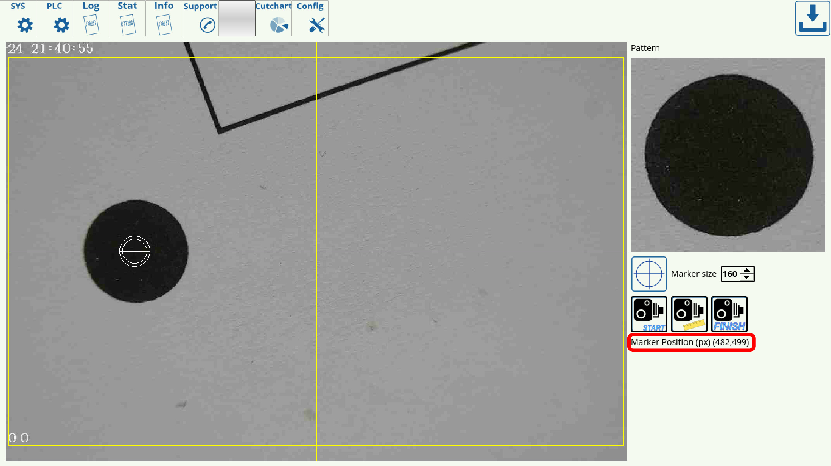
- Click Calibrate. The software will automatically move a set distance in both the x- and the y-axes to determine the pixel to length coefficients.
The calibration process should be complete after the camera has moved in both the positive and the negative directions in both axes, and the results should be registered in Settings > Config > Camera:

Setting up the pixel to length coefficients
Obsolete method only used on program versions older than July 2019. In all recent versions the pixel to length coefficients is calculated automatically by the program during the calibration process.
Using the hotkeys to move the camera
In order to move the camera straight from the Camera tab, a set of hotkeys have been designed specifically for that purpose. Note that the hotkeys are only present in the more recent versions of myCNC software. Please update the myCNC application if the camera hotkeys are not present in your profile version.
| HOTKEY | ACTION |
Arrow Up | Move in the positive y-direction |
Arrow Right | Move in the positive x-direction |
Arrow Down | Move in the negative y-direction |
Arrow Left | Move in the negative x-direction |
Space | Switch the step jog size (00.1 through 1 mm) |
Hold Control and Arrow keys | Move by the selected step jog |
CNC Vision Example
The CNC Vision correction of a program to be used on a shifted or distorted working material can be done easily after the markers have been calibrated. In order to open and use a file with the CNC Vision system, use the following instructions:
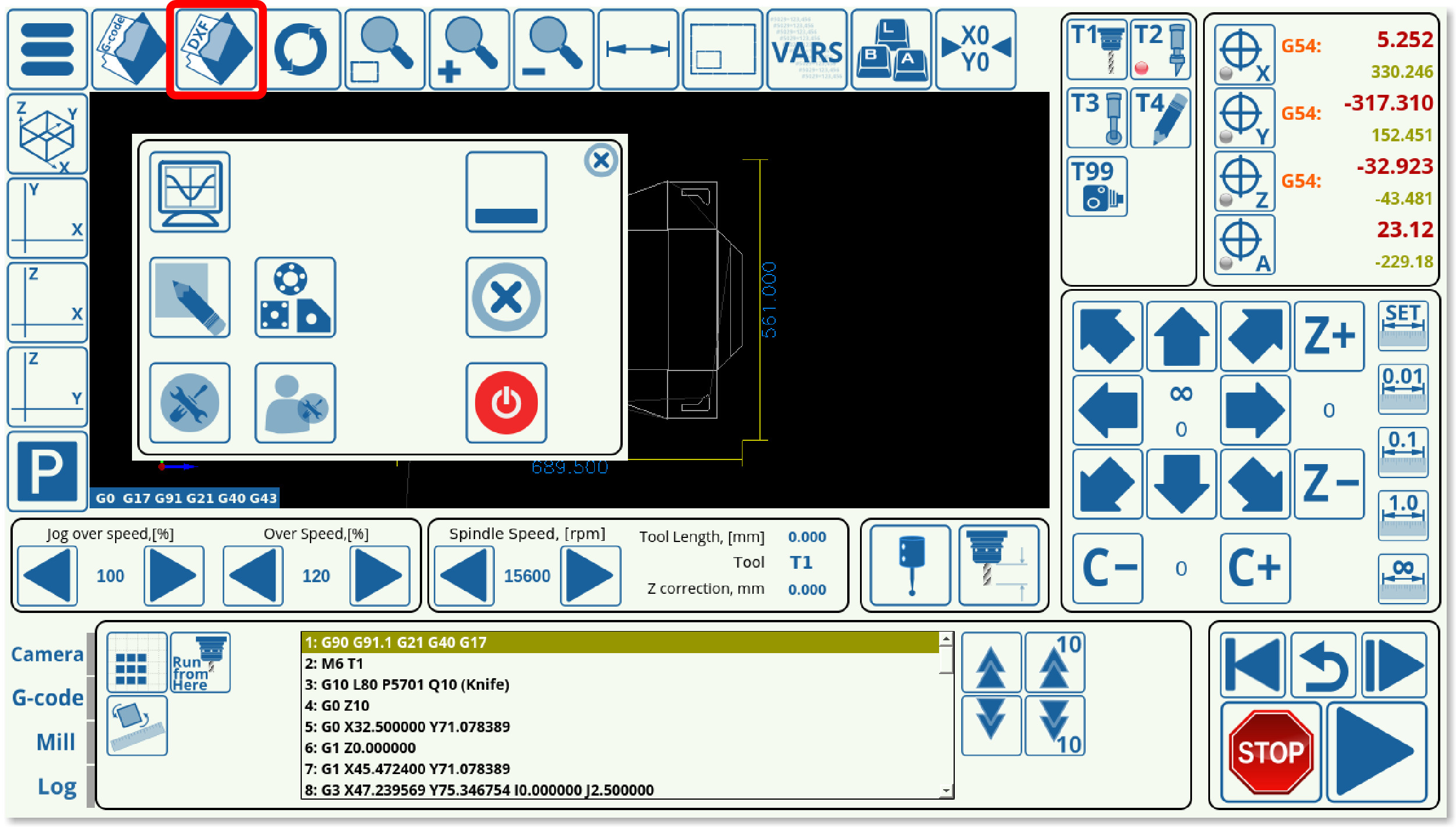
1. From the myCNC software's main screen, click the Open DXF File button.
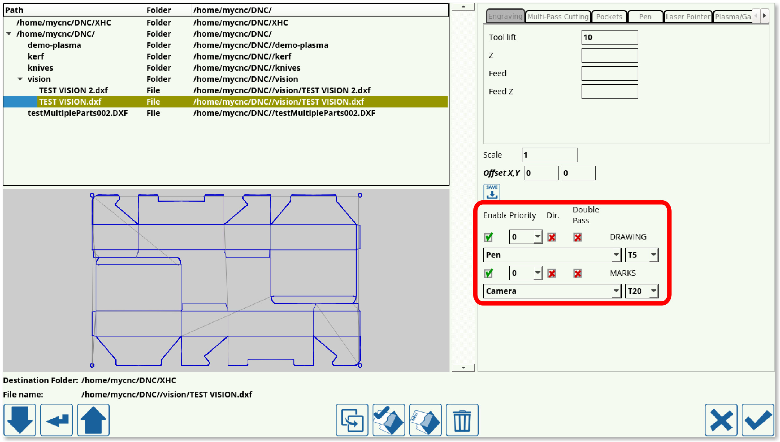
2. Select the particular DXF file you would like to open.
3. When selecting the tools, include Camera as one of the tools, and assign to it the same tool number as the one specified in the Camera Settings (this will be Tool 99 in our case). Assign the other tool or tools and their priorities as necessary for your particular program.
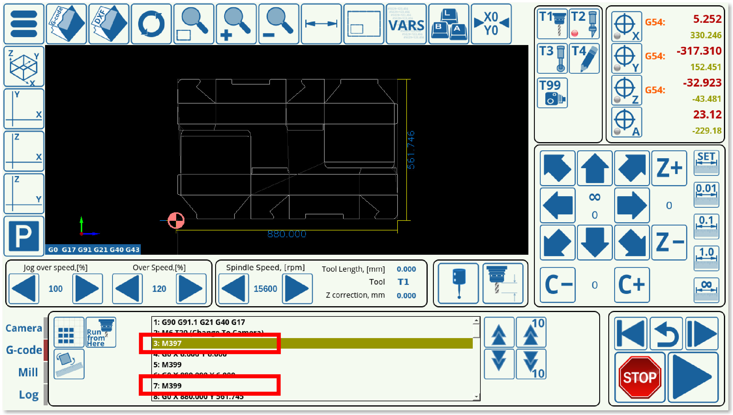
4. Once you have loaded the DXF file, the program should now have inserted the M397, M398, and M399 macros which refer to camera actions into the program G-code.
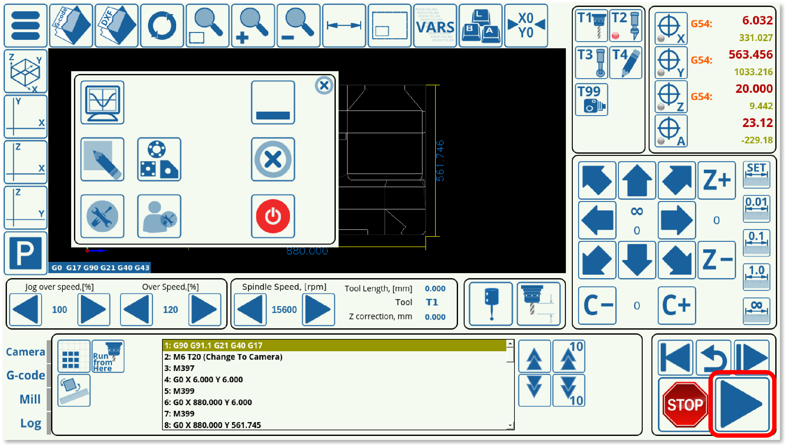
5. Press Run.
The machine will move the camera towards the supposed marker positions, and, if the markers are not immediately present in the Region of Interest, will move around this supposed marker position by the distance specified by the Camera Shift. After running through the camera macros and locating all of the markers for which the program has been calibrated, the program will automatically adjust for any shift or distortion that was introduced, and will immediately begin running the main program.
NOTE: The program will not begin the main cutting process unless all the markers that were expected to be adjusted for have been located.
Camera troubleshooting
A camera troubleshooting guide is available here: Camera Troubleshooting
Creating the DXF files
A suitable DXF file can be created in an application such as Inkscape. A few rules to follow:
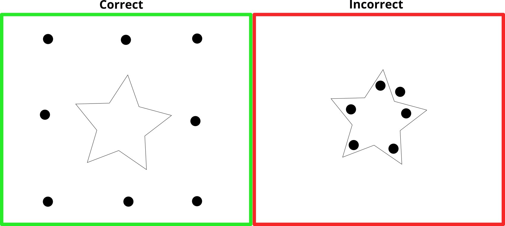
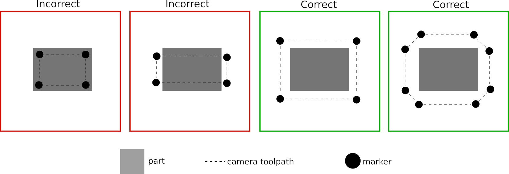
1. The markers should be located outside the part contour (rather than inside of it):
Note the way in which the contour connecting the camera markers needs to be fully outside the contour of the file being corrected in order to work properly:
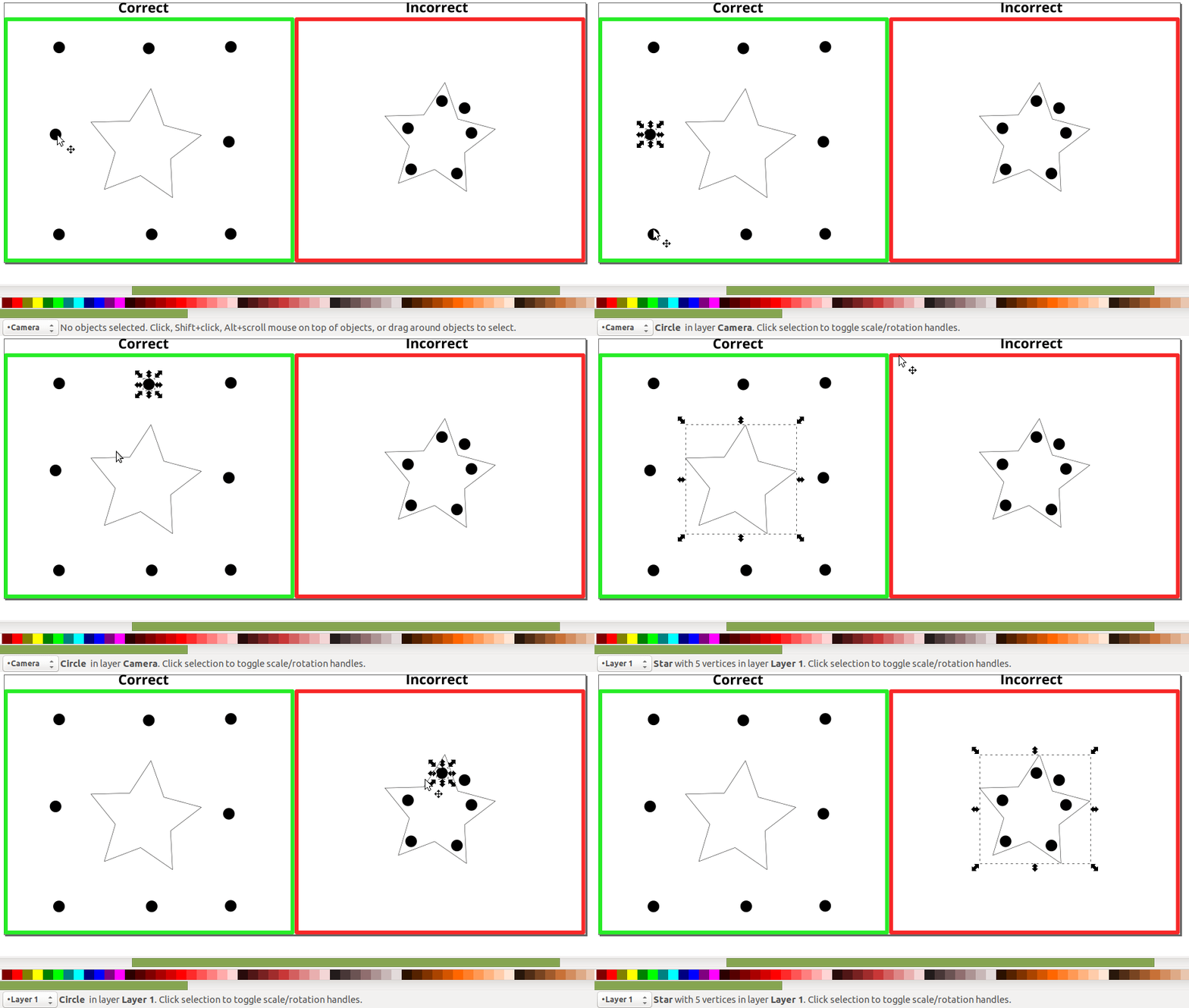
2. The markers and the part contour should be located in different layers (such as Layer 1 for the working part and Camera for the markers), for example:
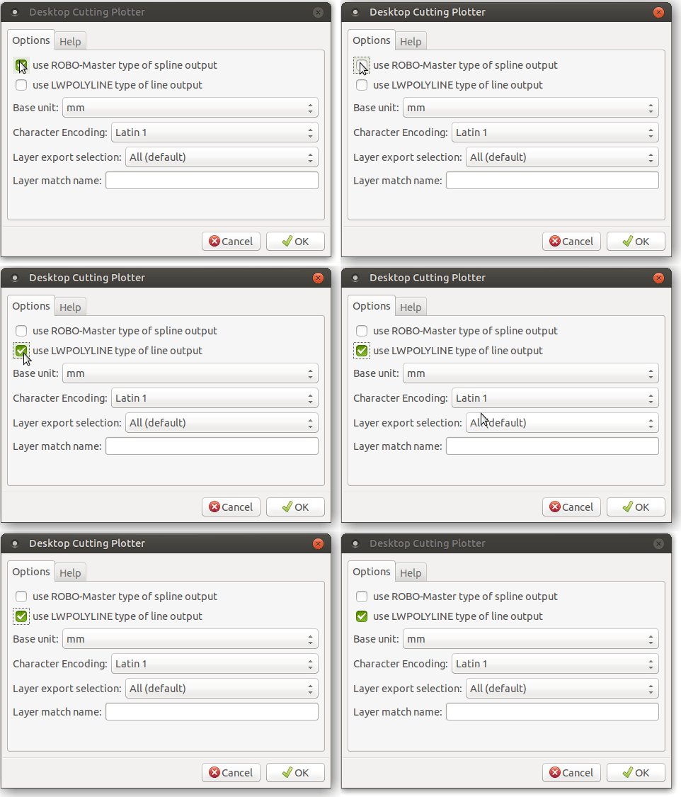
3. If using Inkscape, make sure to export using the LWPOLYLINE option (instead of the ROBO-Master type):

