Table of Contents
Triggers
- A trigger is a function of automatic program tracking of the state of a selected input sensor with a reaction in the form of performing a pre-selected procedure for a PC.
Frequently, most sensors do not require constant monitoring during continuous program operation, for example, at idle transitions or at the time of stopping or inactivity of equipment. But the tasks at certain points of the equipment operation, which require quick reaction on the selected sensor. In such cases, the fastest method of processing will be to enable the trigger and assign it to the required controller input with enabling automatic tracking of the change in the state of the signal level at the selected input, and when the state changes in the right direction (from “0” to “1” or “ 1 “in” 0 ”) to perform the necessary actions. The trigger as a function is faster than the usual input processing inside the plc procedure. A striking example of the work of the trigger is the work of the sensor “arc response” on plasma cutting. The state of this sensor requires constant processing only during the operation of the plasma source, in the cutting process. When the plasma source is turned off (i.e., at idle transitions or in the process of waiting), tracking of the sensor is not required. Therefore, the response of the sensor during the waiting time should be ignored, but during the cutting process, the response to the sensor should be as fast as possible.Therefore, this sensor is most convenient to handle using a trigger.
myCNC software supports up to 4 Triggers.
- It's possible to configure Input Number and Edge Type (Rising or Falling) to activate the Trigger.
- Each trigger can be Enabled of Disabled in PLC procedure. If the Trigger is disabled, all activity on configured input is ignored;
- If trigger is enabled and programmed Rising/Falling Edge happens, Trigger activated and starts PLC procedure defined as Slot
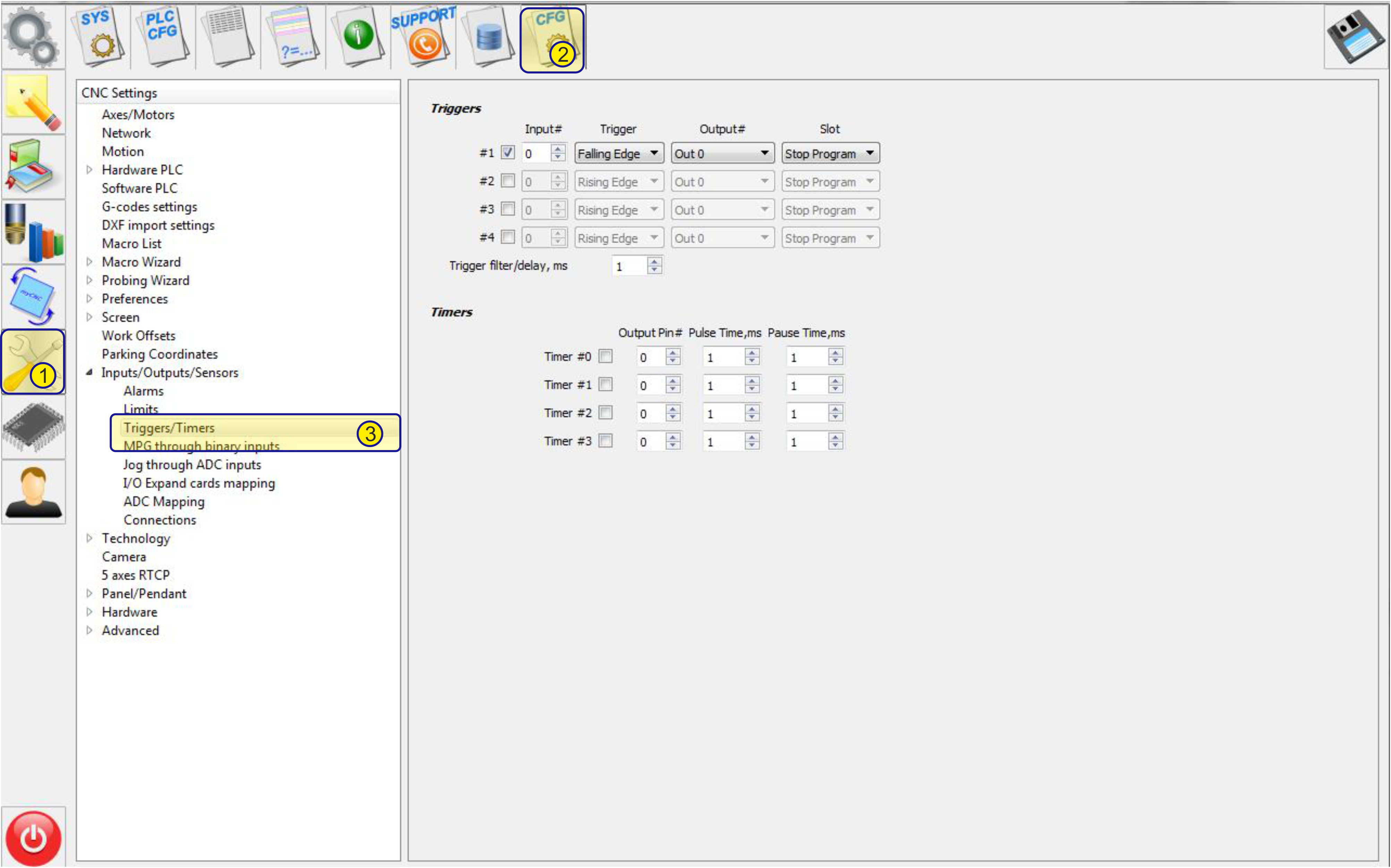
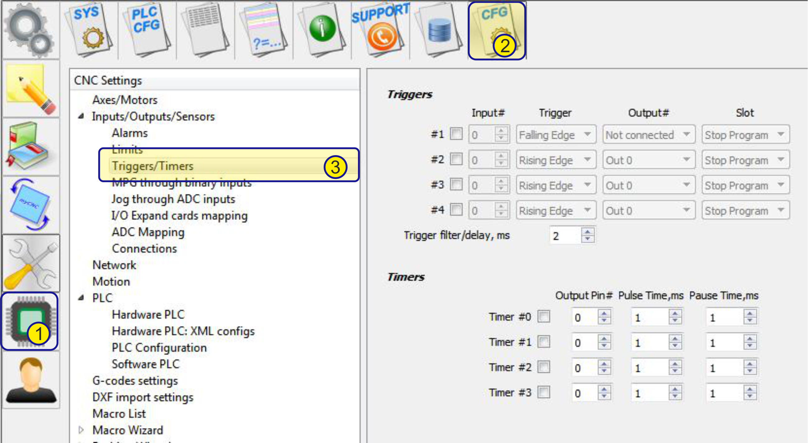
Main window:
 Basic functions:
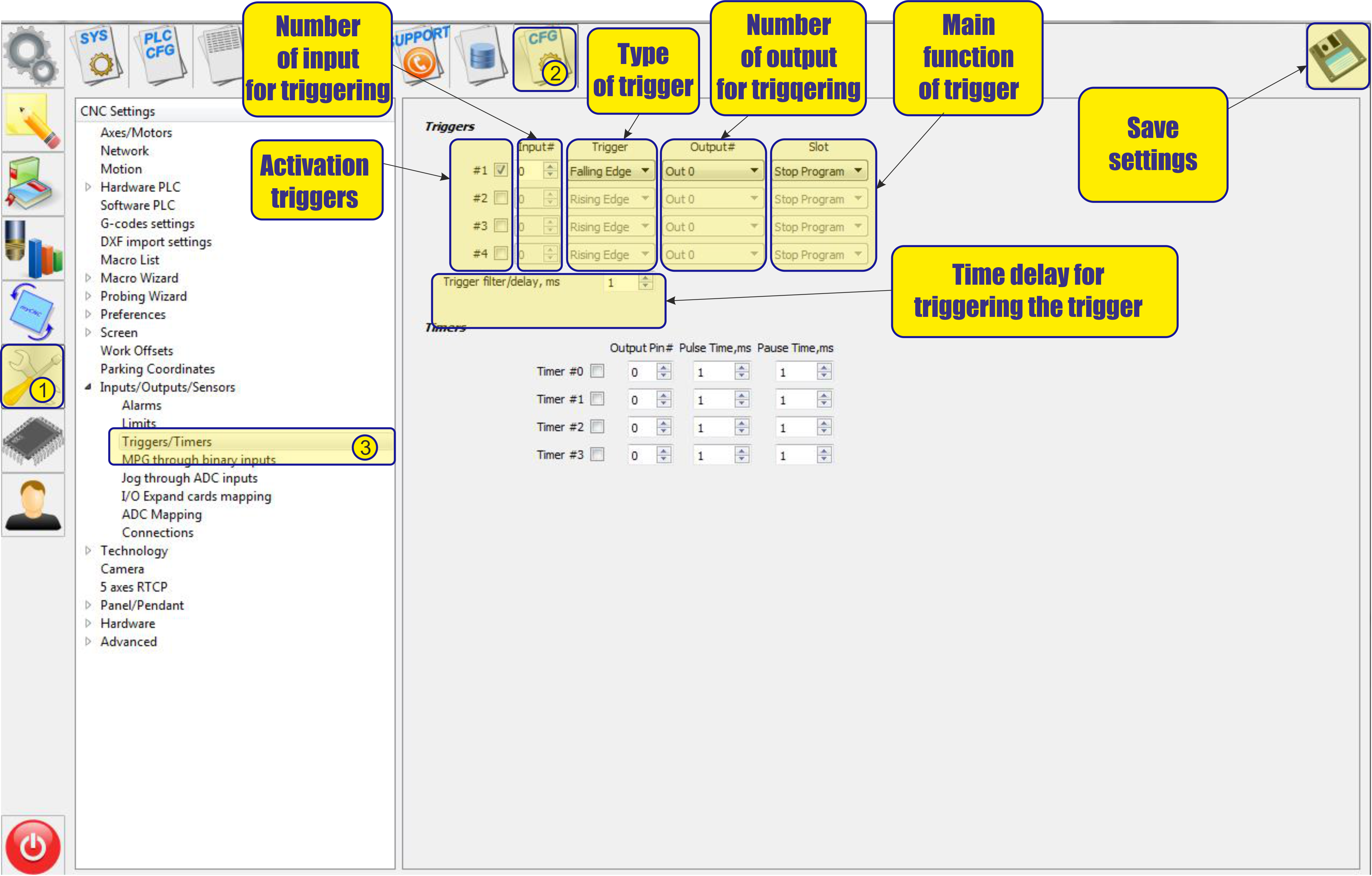
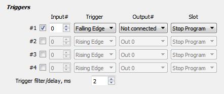
- To activate the trigger , it is necessary to check the box next to number of trigger:
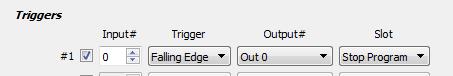
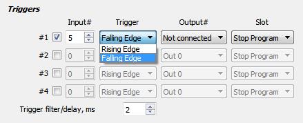
- Then select the type of triggering the trigger.
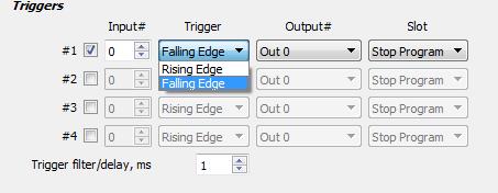
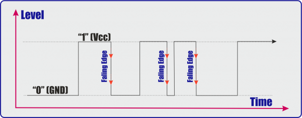
- Faling Edge - Trigger triggering on the falling edge of the impulse, i.e. when passing from the upper state (“1”) to the lower state (“0”).
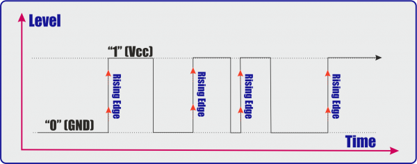
- Rising Edge - Trigger triggering on the rising edge of the impulse, i.e. when passing from the lower state (“0”) to the upper state (“1”).
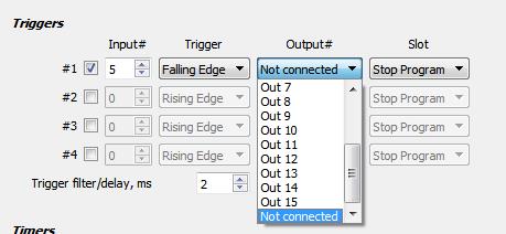
- After tripping, you can select the controller's output
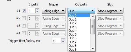
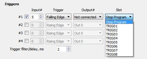
- You can also choose to start the necessary procedure for triggering the trigger
Examples of usage Tiggers:
Example "Arc ON"
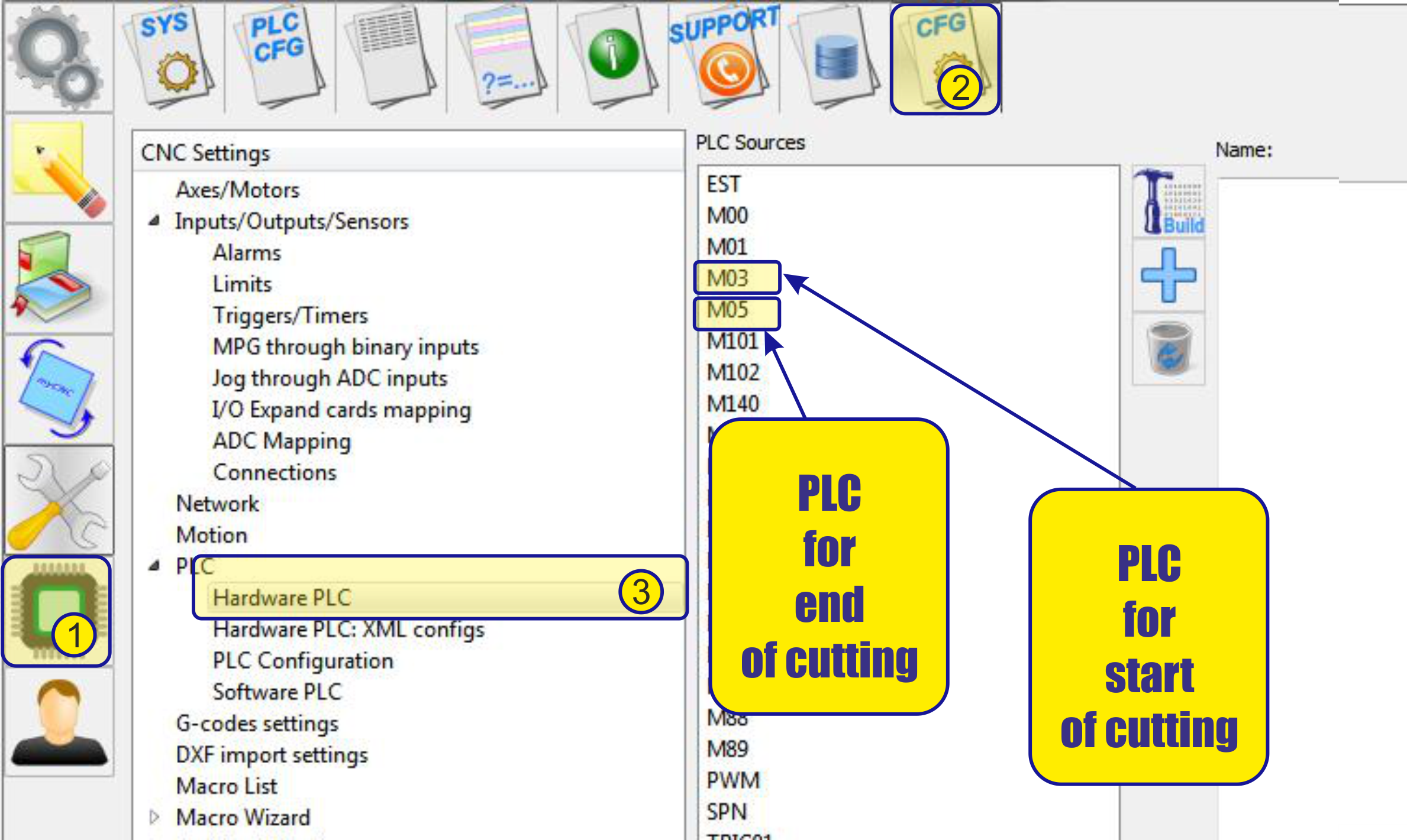
Arc ON signal from Plasma power source represents current Plasma Arc state. Running program should be stopped if the signal failed during cutting. The signal Falling during “no cutting” operation should be ignored. A solution is to set up “Arc ON” input, falling edge as Trigger, Enable the trigger just after piercing operation in M71/M03 PLC procedures and disable it in M74/M05 PLC procedures just before OFF plasma power source.
- For example, take the following conditions: an arc sensor is connected to input number 5 of the ET10 controller. Upon the arrival of the signal “1” from this sensor, we must start moving along the program and start monitoring the input so that when the value changes from “1” to “0” the program will be stopped.
- First, set up the trigger in the appropriate section.
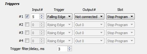
- Since we arc sensor connected to input number 5.
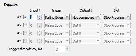
- , this input is selected in the settings of the trigger. And since it is necessary to monitor the transition from “1” to “0”, select the “Falling Edge” trigger type in the settings
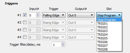
- Since you just need to stop the program, we don’t need to use any of the controller outputs, so the “output #” field is left empty.
- Since the trigger we want to stop the program, it is necessary in the “slot” select the “stop program”
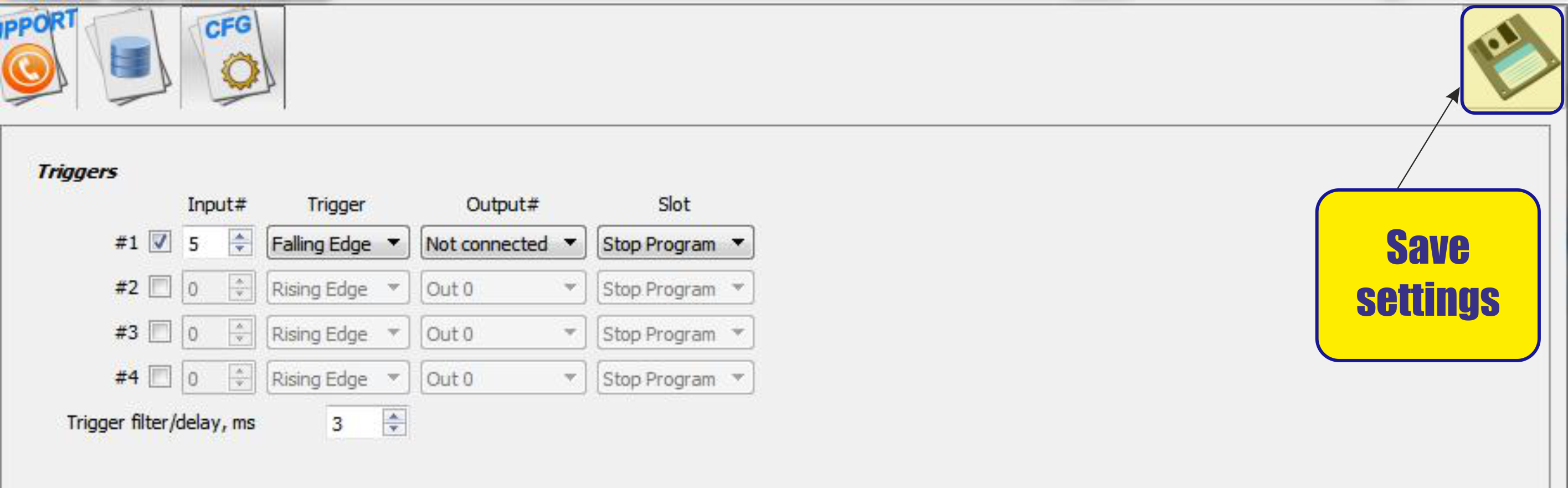
- To avoid false triggering, set the temporary filter to 3 ms, i.e. during this time, the program will monitor the status of the trigger, and if during this time the status of the trigger changes several times, this operation will be considered false.
- This completes the installation of the trigger in this menu, it remains only to save the settings.
- Next, you need to use this trigger in the plz procedure of cutting on (M71 or M03) and in the cutting off procedure (M74 and M05).
M71/M03 example procedure
#define relay_PLAZMA_ON 2
#define input_ARC_READY 5

main()
{
	timer=0;
	portset (relay_PLAZMA_ON);
	timer=timeout_plasma_ready; //wait till plasma arc ready
	timer=5000;
	do
	{
		timer--;
		a=portget(input_ARC_READY);
		if (a!=0) { timer=0; };
	}while(timer>0); //pause

	a=portget(input_ARC_READY); //doublecheck arc sensor
	if (a==0)
	{
		message=PLCCMD_TRIGGER1_ON;
		timer=3;do{timer--;}while(timer>0);
	}
	else
	{
		portclr(relay_PLAZMA_ON);
		exit(plc_exit_plasma_fail);
	};
	exit(99);
};
M71/M03 Procedure description
- We assign the variable “relay_PLAZMA_ON” a value of 2. This variable determines the number of the output responsible for the inclusion of the plasma cutting source in the work.
#define relay_PLAZMA_ON 2
- We assign the variable “input_ARC_READY” a value of 5. This variable determines the number of the “arc sensor” input from the plasma cutting source.
#define input_ARC_READY 5
- timer-This variable is temporary and is used to start timers at different intervals.
timer=0;
- portset (relay_PLAZMA_ON)-Set the output to control the source in the on state.
portset (relay_PLAZMA_ON);
- We start the timer for 5 seconds (5000 ms) (timer=5000;). During this time, we check the state of the input of the “arc sensor” for a state change, i.e. transition from the value “0” to the value “1” (a=portget(input_ARC_READY);). When the state changes and the input value “1” is received, the timer expires (if (a!=0) { timer=0; };).
timer=5000;
do
{
  timer--;
  a=portget(input_ARC_READY);
  if (a!=0) { timer=0; };
}while(timer>0); //pause
- Re-check the status of the “arc sensor” input (a=portget(input_ARC_READY);). When confirming the input trigger when the value “1” appears at the input, instead of the value “0”, we start the program trigger (message=PLCCMD_TRIGGER1_ON) that was previously configured. Now the program will automatically follow the change in the state of the “arc sensor” input and the state change at the sensor input, when going from “1” to “0” (falling edge), the cutting map will be left blank. (timer=3;do{timer–;}while(timer>0);) - program pause 3ms.
a=portget(input_ARC_READY); //doublecheck arc sensor
if (a==0)
{
  message=PLCCMD_TRIGGER1_ON;
  timer=3;do{timer--;}while(timer>0);
}
- If there is no confirmation of input triggering, i.e. the input state will remain equal to “0” (else)- we consider switching on unsuccessful and interrupt the procedure and carry out the exit from the procedure by mistake (exit(plc_exit_plasma_fail);), with switching off the source of plasma cutting(portclr(relay_PLAZMA_ON);).
else
{
  portclr(relay_PLAZMA_ON);
  exit(plc_exit_plasma_fail);
};
M74/M05 example procedure
#define relay_PLAZMA_ON 2
#define input_ARC_READY 5

main()
{
	timer=0;
	portclr (relay_PLAZMA_ON);
	message=PLCCMD_TRIGGER1_OFF;
	timer=3;do{timer--;}while(timer>0);
	exit(99);
};
M74/M05 Procedure description
- We assign the variable “relay_PLAZMA_ON” a value of 2. This variable determines the number of the output responsible for the inclusion of the plasma cutting source in the work.
#define relay_PLAZMA_ON 2
- We assign the variable “input_ARC_READY” a value of 5. This variable determines the number of the “arc sensor” input from the plasma cutting source.
#define input_ARC_READY 5
- timer-This variable is temporary and is used to start timers at different intervals.
timer=0;
- portclr (relay_PLAZMA_ON)-Set the output to control the source is shut down.
portclr (relay_PLAZMA_ON);
- We swith off the program trigger (message=PLCCMD_TRIGGER1_OFF). Now the program will not automatically follow the change in the state of the “arc sensor” input. (timer=3;do{timer–;}while(timer>0);) - program pause 3ms.
    message=PLCCMD_TRIGGER1_OFF;
    timer=3;do{timer--;}while(timer>0);
Example "Probing operations"
- Probing operations. Events from probe sensor should be handled while probing operations. However, Probe input activated while normal moving might be in fact hitting the probe into the material. It can lead to Probe sensor breakage and run should be stopped immediately. A solution is to set up probe input as a trigger, configure Immediate Stop in the Slot PLC procedure and disable the trigger while probing operations ONLY.