Table of Contents
MyCNC Setup Examples
NOTE: The myCNC team recommends utilizing the examples provided in this manual (as well as other manuals in this documentation) as a starting point for your machine setup. When possible (and applicable), it is recommended to keep changes to a mininum. In general, using these examples as the basis for your PLCs/macro commands allows for an easier setup process.
How to set up Axes and Pulses per Unit
Video tutorial:
During the initial setup, the axes on your machine (X, Y, Z, A, etc) may be plugged differently from the desired software configuration. In order to assign the correct motor to the axis in the myCNC software:
1. Go to CNC Settings > Axes/Motors
2. Navigate to Motor Outputs Configuration
3. Assign the connected motors to the needed axes.

In the same window, the general calibration for the pulses per unit can be performed. This is done in order to calibrate the software readings of the machine (how much the machine “thinks” it has moved) versus the actual physical movements of the machine (how much it has actually moved). To do that:
1. Physically record the position of the spindle/knife/sensor/etc on the machine with a ruler, caliper, camera attached to the machine arm, etc.
2. In the myCNC software, move the machine a set distance (for example, 50 mm).

3. Measure the new physical position of the machine and record the distance actually physically traveled.
4. Divide the actual distance by the software distance (for example, 25 mm actually traveled divided by 50 mm that the software recorded)
5. Divide the number of Pulses per Unit from the myCNC software CNC Settings > Axes/Motors window by the coefficient from step #4.

6. Input the new number of pulses per unit into the software.
If the new number of pulses per unit is brought up too high without changing the maximum motor speed, the motors will start making jerking movements when moved. This is due to keeping the Max Speed the same. In order to eliminate the jerking movements, bring down the Max Speed value in CNC Settings > Axes/Motors until the movement is smooth again.

Max Speed is set in units/second (mm/s or inch/s), depending on what units you have chosen in your G-codes settings.
- NOTE: Overspeed acts in a manner similar to CPU overclocking. Motion acceleration is increased together with motion speed when the overspeed is increased. Since toolpath planner does not have access to “Overspeed” value, a significant increase in Overspeed value up from 100% may cause issues, especially for analog servo control. Overspeed should be limited to 100% if you need to be sure the machine does not exceed “Max Speed”.
7. Set the Backlash in units (mm/inch) for each axis. Backlash is the value that allows for some unexpected play in the machine due to clearance or looseness of mechanical parts. When the controller sends a movement command to the motor, the motor may turn briefly before any actual axis movement begins. That turn is defined as backlash, and can be accounted for in this setting.
How to set up Tangential Knife Cutting
MyCNC control has built-in tangential knife control
Tangential knife control is activated by writing “1” to Global Variable #7005 (GVAR_TANGENTKNIFE_ENABLE)
If Tangential control is activated, 2D tool path programming is enough to make tangential knife cutting. myCNC control software automatically
- Calculates the angle of next motion;
- Lifts up the knife to safe height;
- Rotate knife accordingly next XY motion direction;
- Moves down knife on working height.
How to set up a Probing Wizard in Mill profile
In order to properly set up a probe system on a mill profile from scratch on your machine (especially if the software has not, for any reason, been updated to its latest version) please consult the QuickStart manual for the probe sensor setup:
How to set up a Lathe/Turning machine
1. Select Basic profile as “Lathe” in Cfg - Preferences - Common dialog

2. Select “Lathe Visualisation” in Cfg - Preferences - 3D visualisation configuration dialog
3. Select axes X, Z for visualisation and deselect the rest axes.

4. Check G-code settings related to Lathe operations in Cfg - Preferences - G-codes settings configuration dialog

5. Goto Cfg - Technology - Lathe configuration dialog and setup appropriate settings

How to set up a Multi-Tool router
We will put here some process of setup multi-tool router. The router has -
- 2x motors on X axes.
- 2x separate spindles installed on separate Z heads.
- Tangential knife head
1. Inputs/Outputs assignment described on “pins.h” includes the file in Hardware PLC Builder area -
- pins.h
//input/output definitions
//inputs
#define INPUT_HOME_X_MASTER 	0
#define INPUT_HOME_X_SLAVE 	1
#define INPUT_HOME_Y 		2
#define INPUT_HOME_Z1 		3
#define INPUT_HOME_Z2 		4
#define INPUT_HOME_KNIFE 	5
#define INPUT_E_STOP 		7

//Outputs
#define OUTPUT_SPINDLE		0
#define OUTPUT_VAC_POWER	1
#define OUTPUT_VAC_DOWN		2
#define OUTPUT_HOMING 		5
#define OUTPUT_KNIFE 		6

2. How to switch between spindles (Z1/Z2) heads.
Axis pulse-dir signal can be connected/disconnected from Motor output by writing to CNC registers 0x70…0x75 (112…117)
- 0x70 (112) - Motor output #0
- 0x71 (113) - Motor output #1
- 0x72 (114) - Motor output #2
- 0x73 (115) - Motor output #3
- 0x74 (116) - Motor output #4
- 0x75 (117) - Motor output #5
Low 4 bits (0..3) of the writing value represent Axis to connect -
- 0 - X
- 1 - Y
- 2 - Z
- 3 - A
- 4 - B
- 5 - C
- 15 - disconnected
pulse-dir Direction will be changed (DIR signal inverted) if Bit #4 is set.
This way we add PLC procedures M201 and M202 to switch Z axis between Motor outputs #3 and #4
- M201.plc
#include vars.h
main()
{
  parameter=15;   //OFF
  command=112+3;  //channel 3
  message=PLCCMD_SET_CNC_VAR;
  timer=2;do{timer--;}while(timer>0);

  parameter=2+16;	   //Attach to Z
  command=112+4;   //channel 4 turning off
  message=PLCCMD_SET_CNC_VAR;
  timer=2;do{timer--;}while(timer>0);

  exit(99);
};
- M202.plc
#include vars.h
main()
{
  parameter=15;   //OFF
  command=112+4;  //channel 4
  message=PLCCMD_SET_CNC_VAR;
  timer=2;do{timer--;}while(timer>0);

  parameter=2+16; //Attach to Z
  command=112+3;  //channel 3
  message=PLCCMD_SET_CNC_VAR;
  timer=2;do{timer--;}while(timer>0);

  exit(99);
};

3. Homing for Z1, Z2 axes can be configured in Macro Wizard. M133 macro is usually used for Homing Z procedure. We will use macro names M1331 and M1332 for 2 homing procedures for every Z axis.
- M1331
M201 (Turn ON Z1 axis, OFF Z2 axis)
G10 L80 P5521 Q1
G10 L80 P5525 Q1
M88 L0 P3(Soft stop when sensor triggered)
G91 G0 Z   200.0000 F   600.00
G04 P0.1
M89 L1 P3(Quick stop when sensor triggered)
G91 G0 Z  -200.0000 F    30.00
G04 P0.1
G91 G0 Z     1.0000 F   500.00
G90 G10L70 P0 Z #5453
G10 L80 P5521 Q0
G10 L80 P5525 Q0
G10 L80 P7393 Q0 (Homing Flag)
- M1332
M202 (Turn OFF Z1 axis, ON Z2 axis)
G10 L80 P5521 Q1
G10 L80 P5525 Q1
M88 L0 P4(Soft stop when sensor triggered)
G91 G0 Z   200.0000 F   600.00
G04 P0.1
M89 L1 P4(Quick stop when sensor triggered)
G91 G0 Z  -200.0000 F    30.00
G04 P0.1
G91 G0 Z     1.0000 F   500.00
G90 G10L70 P0 Z #5453
G10 L80 P5521 Q0
G10 L80 P5525 Q0
G10 L80 P7393 Q0 (Homing Flag)

4. M138 macro is used for Home-All procedure. It should be fixed to support Z1, Z2, tangential knife homing and OUTPUT_HOMING output described in “pins.h”
- M138
M62P5 (OUTPUT HOMING ON)

M135 (C-knife)

M1331 (Z1)
M1332 (Z2)

M132 (Y)
M131 (X)

M63P5 (OUTPUT HOMING OFF)

5. M6 - Tool Change macro for multitool configuration.
- M6
M600 P#5409

if [ #5409 NE 1 ] 100
M150
GOTO 1000

N100
if [ #5409 NE 2 ] 200
M151
JUMP 1000

N200
if [ #5409 EQ 3 ] 300
G10 L80 P7005 Q0
JUMP 1000

N50
G10 L80 P7005 Q1


N300

N1000
G10 L81 P5400 Q5409    (set current tool number)
How to set up a Multi-Tool Tangential Cutter
 Section under construction
For tangential cutting, a common scenario is for the system switch between two different motors for both the Z and the C axes (to switch between the tangential knife and the creasing wheel, for instance). Therefore, the system will have:
- X- and Y-axes motors
- Two different motors for the Z-axis (for knife and wheel up-down movement)
- Two different motors for the C-axis (for knife and wheel rotation)
1. How to switch between motors:
Axis pulse-dir signal can be connected/disconnected from Motor output by writing to CNC registers 0x70…0x75 (112…117)
- 0x70 (112) - Motor output #0
- 0x71 (113) - Motor output #1
- 0x72 (114) - Motor output #2
- 0x73 (115) - Motor output #3
- 0x74 (116) - Motor output #4
- 0x75 (117) - Motor output #5
Low 4 bits (0..3) of the writing value represent Axis to connect -
- 0 - X
- 1 - Y
- 2 - Z
- 3 - A
- 4 - B
- 5 - C
- 15 - disconnected
pulse-dir Direction will be changed (DIR signal inverted) if Bit #4 is set.
This way we add PLC procedures M201 and M202 to switch Z axis between Motor outputs #3 and #4
- M201.plc
#include vars.h
main()
{
  parameter=15;   //OFF
  command=112+2;  //motor output #2
  message=PLCCMD_SET_CNC_VAR;
  timer=2;do{timer--;}while(timer>0);

  parameter=2+16;   //Attach to Z-axis, "16" is axis inversion
  command=112+3;   //motor output #3
  message=PLCCMD_SET_CNC_VAR;
  timer=2;do{timer--;}while(timer>0);

  parameter=15;   //OFF
  command=112+4;  //motor output #4
  message=PLCCMD_SET_CNC_VAR;
  timer=2;do{timer--;}while(timer>0);

  parameter=5;	   //Attach to C-axis
  command=112+5;   //motor output #5
  message=PLCCMD_SET_CNC_VAR;
  timer=2;do{timer--;}while(timer>0);

  exit(99);
};
- M202.plc
#include vars.h
main()
{
  parameter=15;   //OFF
  command=112+3;  //motor output #3
  message=PLCCMD_SET_CNC_VAR;
  timer=2;do{timer--;}while(timer>0);

  parameter=2+16; //Attach to Z-axis, "16" is axis inversion
  command=112+2;  //motor output #2
  message=PLCCMD_SET_CNC_VAR;
  timer=2;do{timer--;}while(timer>0);

  parameter=15;   //OFF
  command=112+5;  //motor output #5
  message=PLCCMD_SET_CNC_VAR;
  timer=2;do{timer--;}while(timer>0);

  parameter=5;	   //Attach to C-axis
  command=112+4;   //motor output #4
  message=PLCCMD_SET_CNC_VAR;
  timer=2;do{timer--;}while(timer>0);

  exit(99);
};
2. Homing for Z1, Z2 axes can be configured in Macro Wizard. M133 macro is usually used for Homing Z procedure. We will use macro names M1331 and M1332 for 2 homing procedures for every Z axis.
- M1331
M201 (Turn ON Z1 axis, OFF Z2 axis)
G10 L80 P5521 Q1
G10 L80 P5525 Q1
M88 L0 P3(Soft stop when sensor triggered)
G91 G0 Z   200.0000 F   600.00
G04 P0.1
M89 L1 P3(Quick stop when sensor triggered)
G91 G0 Z  -200.0000 F    30.00
G04 P0.1
G91 G0 Z     1.0000 F   500.00
G90 G10L70 P0 Z #5453
G10 L80 P5521 Q0
G10 L80 P5525 Q0
G10 L80 P7393 Q0 (Homing Flag)
- M1332
M202 (Turn OFF Z1 axis, ON Z2 axis)
G10 L80 P5521 Q1
G10 L80 P5525 Q1
M88 L0 P4(Soft stop when sensor triggered)
G91 G0 Z   200.0000 F   600.00
G04 P0.1
M89 L1 P4(Quick stop when sensor triggered)
G91 G0 Z  -200.0000 F    30.00
G04 P0.1
G91 G0 Z     1.0000 F   500.00
G90 G10L70 P0 Z #5453
G10 L80 P5521 Q0
G10 L80 P5525 Q0
G10 L80 P7393 Q0 (Homing Flag)
3. M6 - Tool Change macro for multitool configuration.
- M6
M600 P#5409

if [ #5409 NE 1 ] 100
M150
GOTO 1000

N100
if [ #5409 NE 2 ] 200
M201
JUMP 1000

N200
if [ #5409 EQ 3 ] 300
M202
JUMP 1000

N50
G10 L80 P7005 Q1


N300

N1000
G10 L81 P5400 Q5409    (set current tool number)
How to setup Homing procedure
Homing is a procedure to find the initial machine position (home position) by using Home sensors. The home procedure is a macro file. The macro filename is absolutely flexible, but we usually use a number of default macro names -
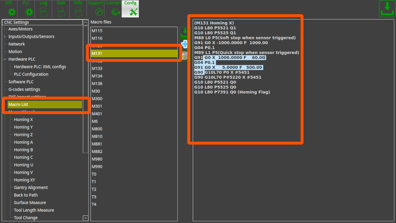
- M131 - Homing for the X axis
- M132 - Homing for the Y axis
- M133 - Homing for the Z axis
- M134 - Homing for A axis
- M135 - Homing for B axis
- M136 - Homing for C axis
- M138 - Homing all the axes (custom macro which does all the axes homing in series)
There are a few ways to send the machine to find homes
- It's possible to configure mandatory homing if CNC control system started and/or an Emergency or Servo drivers alarm event happened.

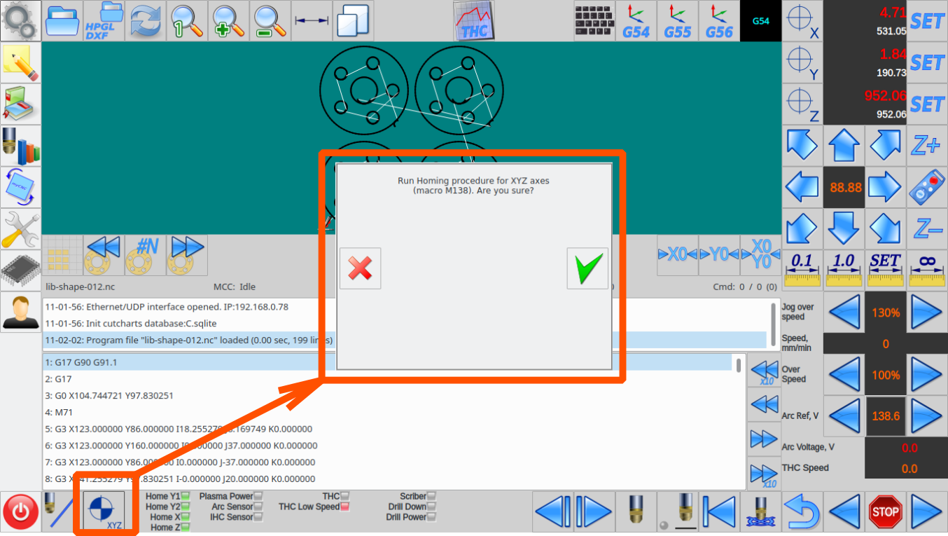
The red button on the message popup widget should be pressed to send a machine to the home position. The popup message will be hidden when all home flags are ready.

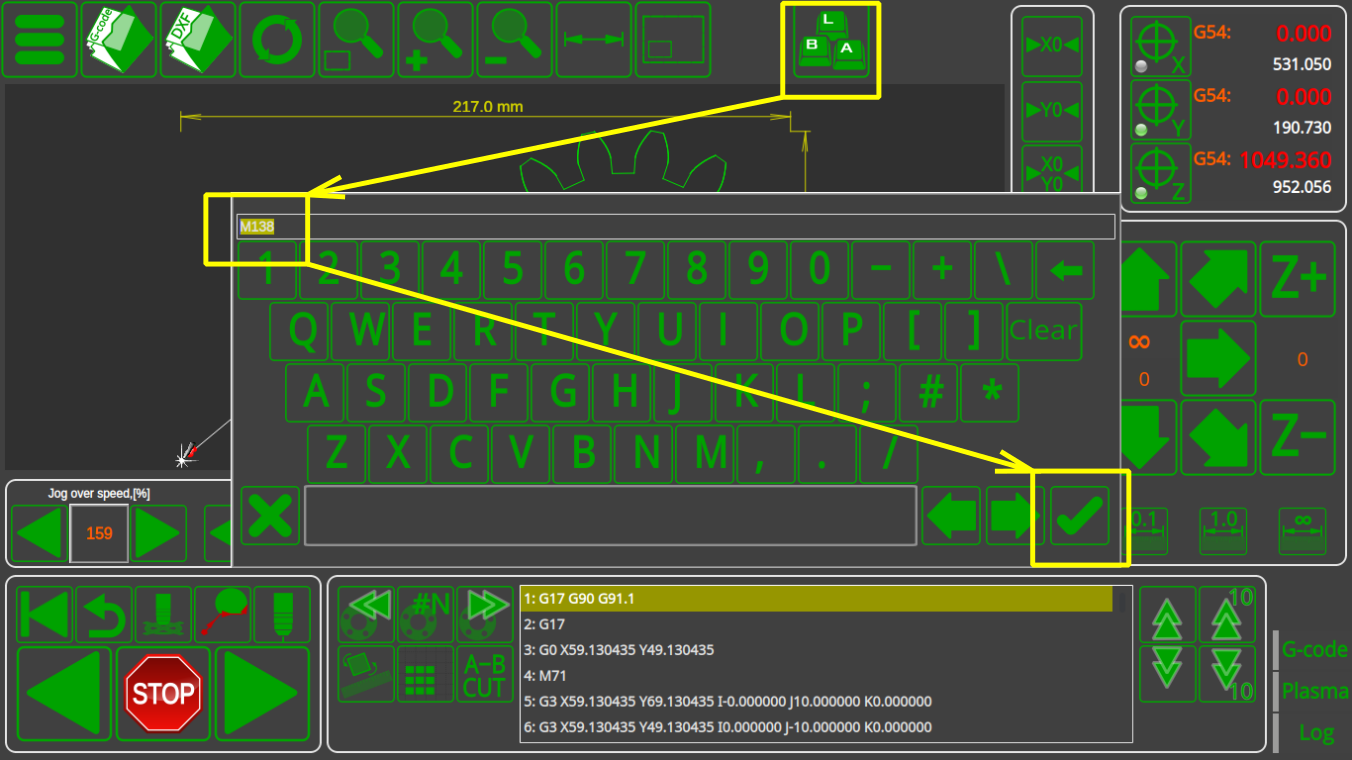
- Home macro procedure can be started from the MDI interface

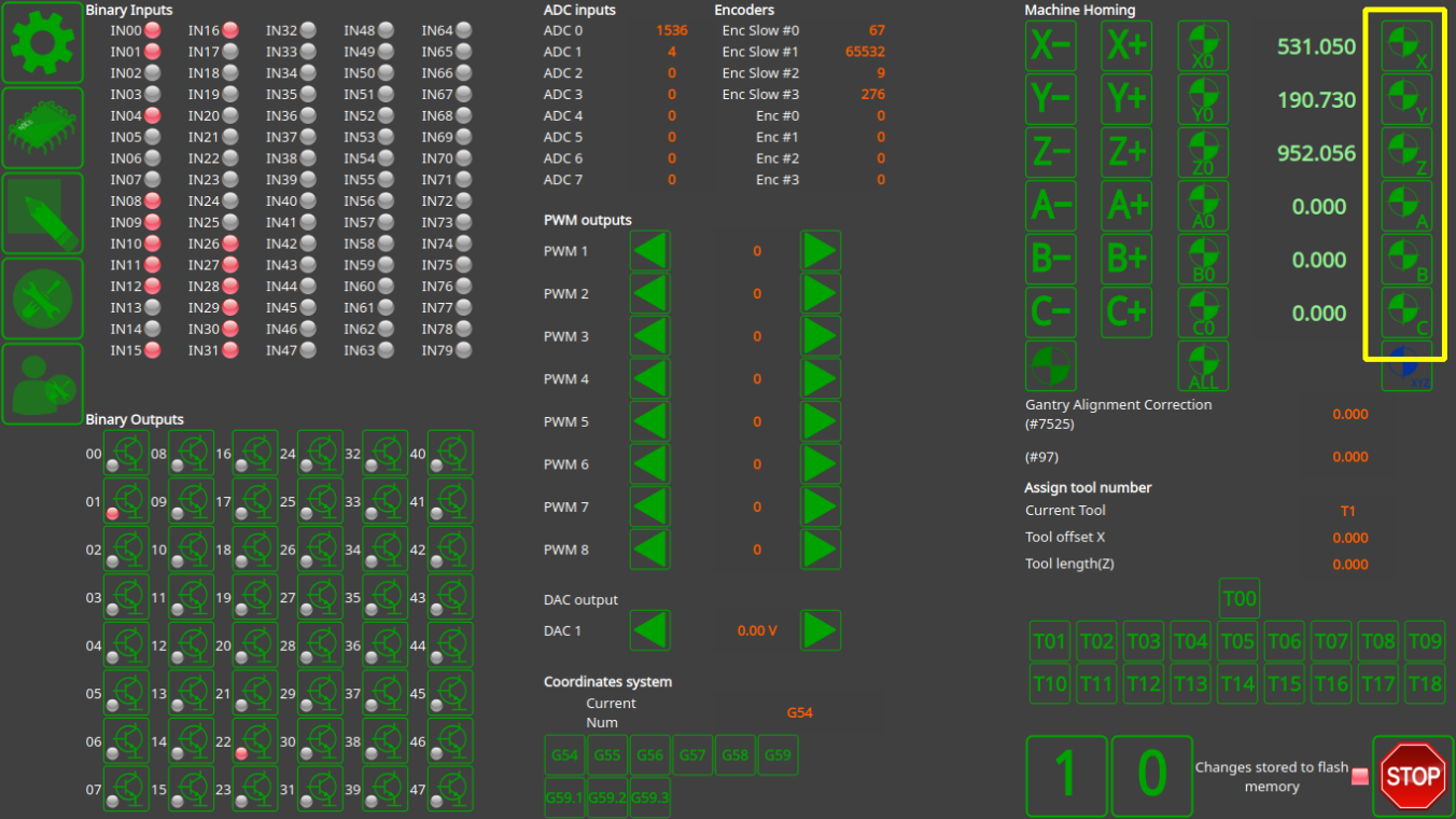
- UI might contain button to send machine home. For example buttons for homing each axis X, Y, Z, A, B, C on diagnose widget
or All the Axes Homing button on the main screen of “1024P-V2” profile


Homing Macro files should be created during machine setup. Macro file can be created
- in “Macro Wizard” conversational dialogs
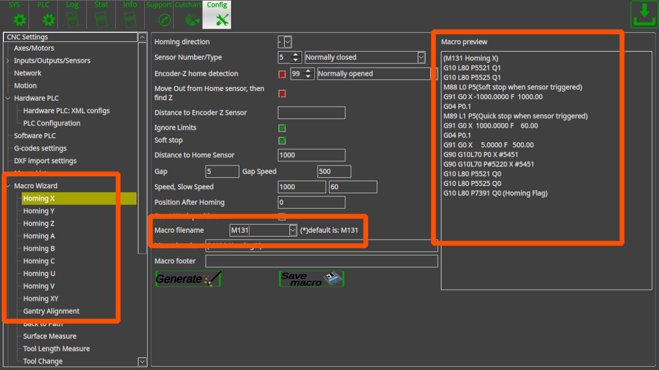
By using the macro wizard you just point homing moving direction, input number used for home sensor, sensor type (normally opened/closed), homing and probing speed, parameters of Encoder Z-label (if used to find precise homing position) and some other parameters. Macro file will be generated on the widget “Macro preview” by pressing “Generate” button. If the macro is ok, the button “Save macro” should be pressed to save macro file on a storage device (HDD, SD card etc). The dialog settings itself might be saved in the configuration file by pressing “Save” button on the top-right corner of the screen. - manually in “Macro List” widget


Home-All macro M138 is a simple macro file which runs in series macro files for all axes. For simple 3 axes machine it would be like this
- M138
M133
M132
M131
Procedure started from Homing Z, then Y and the last is X. Any other sequence can be choosen according to your requirements.

In case Gantry alignment procedure used instead of standard homing procedure, it might have different macro file name to not be mixed-up with standard homing procedure. For example - homing Y is “M132”, gantry alignment is “M1321”. This is just example, any of macro filename can be choosen. THe result of Home-All macro would be
- M138
M133
M1321
M131
Home-All macro can be very different for more complicated machines with multi-spindles, 5 axes and so on. For example M138 macro for multi-spindle machine with tangential knife.
- M138
M62P5 (OUTPUT HOMING ON)

M135 (C-knife)

M1331 (Homing Z1)
M1332 (Homing Z2)

M132 (Homing Y)
M131 (Moming X)

M63P5 (OUTPUT HOMING OFF)
How to set up Homing Handler
If the machine has stopped unexpectedly, due to things like an emergency stop button press/power failure/etc, it is sometimes necessary to prompt the user to run the Homing procedure again before allowing any further actions to be taken in order to safely calibrate the machine. In order to do that, a software PLC is put in place called the HOMING_HANDLER
The Homing Handler can be set up by using the following instructions:
1. Go to Settings > Config > PLC > Software PLC and select HOMING_HANDLER

2. In the HOMING_HANDLER code, put the two forward slashes in front of the exit(99); line, commenting it out.

Note that the axes for which the homing is not required (Axis C in this case) have also been commented out. If only select axes need to be included in the homing procedure after the emergency stop, these can be configured in the code by adding/deleting forward slashes in front of the respective axes' commands.

At this point, in an emergency stop situation, myCNC will prompt the user to run the homing procedure for the selected axes before any other action is taken after starting the machine back up again.
In order to disable the Homing Handler, add the two forward slashes in front of exit(99); again, then Save and reload the application.
How to setup Dual Axis (Slave X, Slave Y)
Dual axis setup is really simple.
Goto "Axes/Motors" configuration
dialog and set the same axis for two motor outputs.
They will work together
For example, motor outputs #0 and #1 are used for the same X axis on the picture below.

Next picture shows how to attach the Y axis to motor outputs #1, #2.

How to set up two instances of myCNC software on one machine
In order to start two instances of myCNC software on a single board Odroid-C2 computer:
1. Go to your Home folder, and in the View menu click Show Hidden Files

2. From your Home folder, navigate to .config > myCNC > profiles, and create folders named 1 and 2

3. Copy the contents of another profile folder (for example, the contents of .config/myCNC/profiles/12805) into both new folders. Here, you can choose which profiles you usually use on your machine.

4. Go back to your home folder, and from there navigate to the myCNC folder (NOTE: this is a different folder from before, so go Home > myCNC instead of Home > .config > myCNC).

5. Open the myCNC.sh file (click Display when asked whether you want to run the file or display its contents).

6. Paste the following code into the file, then save it and close the editor.
#!/bin/bash

cd $(dirname $0)
echo DIRNAME: $(dirname $0)

killall myCNC
killall myCNC

xset s 0
xset -dpms


./C2/myCNC -p1 &

./C2/myCNC -p2
7. Run the myCNC.sh file by selecting Run in Terminal after opening the file. Two instances of myCNC software should now be running.

Setting up a 2-motor X+Y X-Y 3D-printer
A 3D printer shown below is an example of a setup which utilized the X+Y and X-Y axis configuration in Settings → Config → Axes/Motors:
http://forum.pv-automation.com/download/file.php?id=1135&t=1 http://forum.pv-automation.com/download/file.php?id=1134&t=1
Setting up a waterjet system
Certain CAM software packages can automatically insert necessary waterjet M-codes at some desired distance from the corners to properly accelerate and decelerate the machine. These M-codes are M64/M65, as well as M164/M165 - the first two turn a specified output on/off on the fly without stopping (using the special FlyCut license that we provide), while M164/M165 are reserved for controlling the PWM output.
Some profiles within myCNC software (such as X1366P) contain a Software PLC procedure (WATERJET_SLOWSPEED) that works by monitoring the state of the output that the above codes toggle on and off:
 main()
{
 a0=gvarget(7184)&(1<<10);
do{
a1=gvarget(7184)&(1<<10);
if (a0!=a1)
{
 a0=a1;
 if (a0==0) //normal speed
  {
   gvarset(9379,0);
  }else //slow speed
  {
    gvarset(9379,1);
  };
};
}while(1);
};
The above software PLC monitors the state of the desired output and switches the state of the global variable #9379. Writing “1” to this global variable results in a timer being started in the myCNC system, allowing the software, with the help of “Overspeed %” value, to smoothly reduce/increase the speed while passing a corner.
As mentioned before, this functionality requires a FlyCut license, which is available to purchase on request.