Table of Contents
Independent Pulse Generator
myCNC controllers Axis B can be switched to independent pulse generator output.
Independent Pulse Generator was added to firmware dated July 20, 2018.
High level access to the pulse generator
There are a number of global array registers to access to the independent pulse generator
| Register Name | Address | Description |
|---|---|---|
| GVAR_GENERATOR_FRQ_RAW | 8130 | Pulse Generator RAW frequency value, [units] 1 unit = 0.000736 Hz |
| GVAR_GENERATOR_ACCEL | 8131 | Generator Acceleration, [units] 1unit = 0.736 1/c2 |
| GVAR_GENERATOR_FRQ_RATIO | 8132 | Generator Frequency Ratio |
| GVAR_GENERATOR_FRQ | 8133 | Generator Frequency. Frequency*Ratio value is sent to the Generator and saved in the RAW frequency register. |
Originally the Pulse generator was meant to be used as Coolant control. Global register GVAR_PLC_COOLANT_STATE (#7372) is used to detect the Current State of the Pulse generator.
If Generator Frequency register (#8133) is changed -
- RAW value is calculated and stored in the RAW register #8130
- If Coolant Register is NOT zero, the RAW value is sent to the myCNC controller to update current frequency. Changing the RAW register in myCNC controller takes effect immediately.
- If the RAW value is zero, the generator is stopped (with given acceleration).
- If the RAW value is not zero, the generator is started (or current frequency changed accordingly) with given acceleration.
If the RAW register (#8130) is written directly, the value will be sent to the Frequency Generator despite on Current Coolant state (#7372)
Global variable registers can be written in either Hardware or Software PLC.
Q: Why is the Frequency Ratio needed?
A: Internal frequency units do not make sense for a normal user. It is convenient
to set up the ratio and has the Frequency value in a unit that would be usable for a user.
Depending on the Frequency generator application, the unit might be very different.

It may be [1Hz] if you need a simple frequency generator,
or [ml/hour] for Coolant control
or [rpm] for Spindle speed through pulse-dir servo controller.
How to use the pulse generator
The first application we used the Pulse Generator was a Coolant control base on a stepper driver.
Pulse Generator settings in the Software PLC
The rate, ratio and acceleration can be set up in the Software PLC, as well as in the User Settings widget (the Step-Dir Coolant Control section).
“HANDLER_INIT.plc” procedure is started just after the configuration is sent to the myCNC controller. A few lines to set up the Frequency generator can be added there.
- HANDLER_INIT.plc
main()
 {
 gvarset(60000,1);//run Servo ON procedure

 gvarset(8131, 8000); //set Frequency acceleration
 gvarset(8132, 1359); //set Ratio
 gvarset(8133, 0);    //Off the Generator.

 exit(99);
};
MQL (Coolant) Pulse Generator control through Hardware PLC
Function coolant_motor_start() is added to the mill-func.h file
- mill-func.h
coolant_motor_start()
{
  timer=10;do{timer--;}while(timer>0);

  gvarset(8131,1000000); //acceleration
  timer=10;do{timer--;}while(timer>0);

  x=gvarget(8133);//get the speed (frequency)
  k=gvarget(8132);//get the ratio

  x=x*k; //calculate the RAW frequency
  gvarset(8130,x); //send the raw frequency to the register
  timer=30;do{timer--;}while(timer>0); //wait a time for the frequency value to be delivered
};
M08.plc procedure which starts the coolant motor would be the following (note the inclusion of mill-func.h at the beginning of the code):
- M08.plc
#include pins.h
#include mill-func.h

main()
{
  gvarset(7372,1);
  portset(OUTPUT_FLOOD); //
  coolant_motor_start();
  exit(99);	//normal exit
};
A procedure M09.plc to stop a coolant motor is simpler - we simply need to write “0” to the raw frequency register.
Pulse Generator control for Spindle
It is possible to control the spindle speed through the pulse generator. This is done through the independent pulse generator implemented in myCNC, which can be “mixed into” the B axis channel. An independent generator is controlled by writing values to the global variables 8130-8133, as described in the table at the beginning of this page (Register Name / Description table).
When using the GUI elements (buttons, input lines, etc.) it is convenient (and necessary) to use the multiplier and frequency registers when setting the generator frequency (what you see is NOT what you get, as the multipliers convert the human-read values into real machine values). For example, when the operator changes the value of register #8133 (the preset generator frequency), myCNC software will automatically recalculate the value of this preset frequency while taking into account the preset multiplier and will send this data to the controller.
When utilizing the Hardware PLC, you MUST use the “raw” value register entry (8130) and independently take into account the multiplier (in the PLC code), as no such helpful conversion is available.
Independent Pulse Generator Spindle implementation example
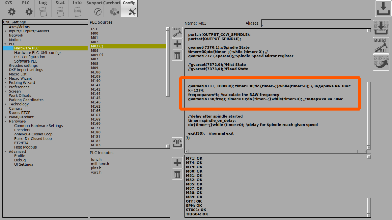
1. Add the code that enables the generator into the Hardware PLC procedure M03.plc (spindle ON procedure). It is convenient to add code to the end of the procedure before the exit(99); line.
  // Set the acceleration of the generator
  gvarset (8131, 100000); timer = 30; do {timer -;} while (timer> 0); // Delay for 30ms

// Convert spindle speed reference to frequency.
  // The value of the coefficient is selected in such a way as to convert
  // 12-bit spindle speed to generator frequency
  k = 123456;
  freq = eparam * k; // Calculate the raw value of the generator frequency

  // Send generator frequency value
  gvarset (8130, freq); timer = 30; do {timer -;} while (timer> 0); // Delay for 30ms

  exit (99); // normal exit
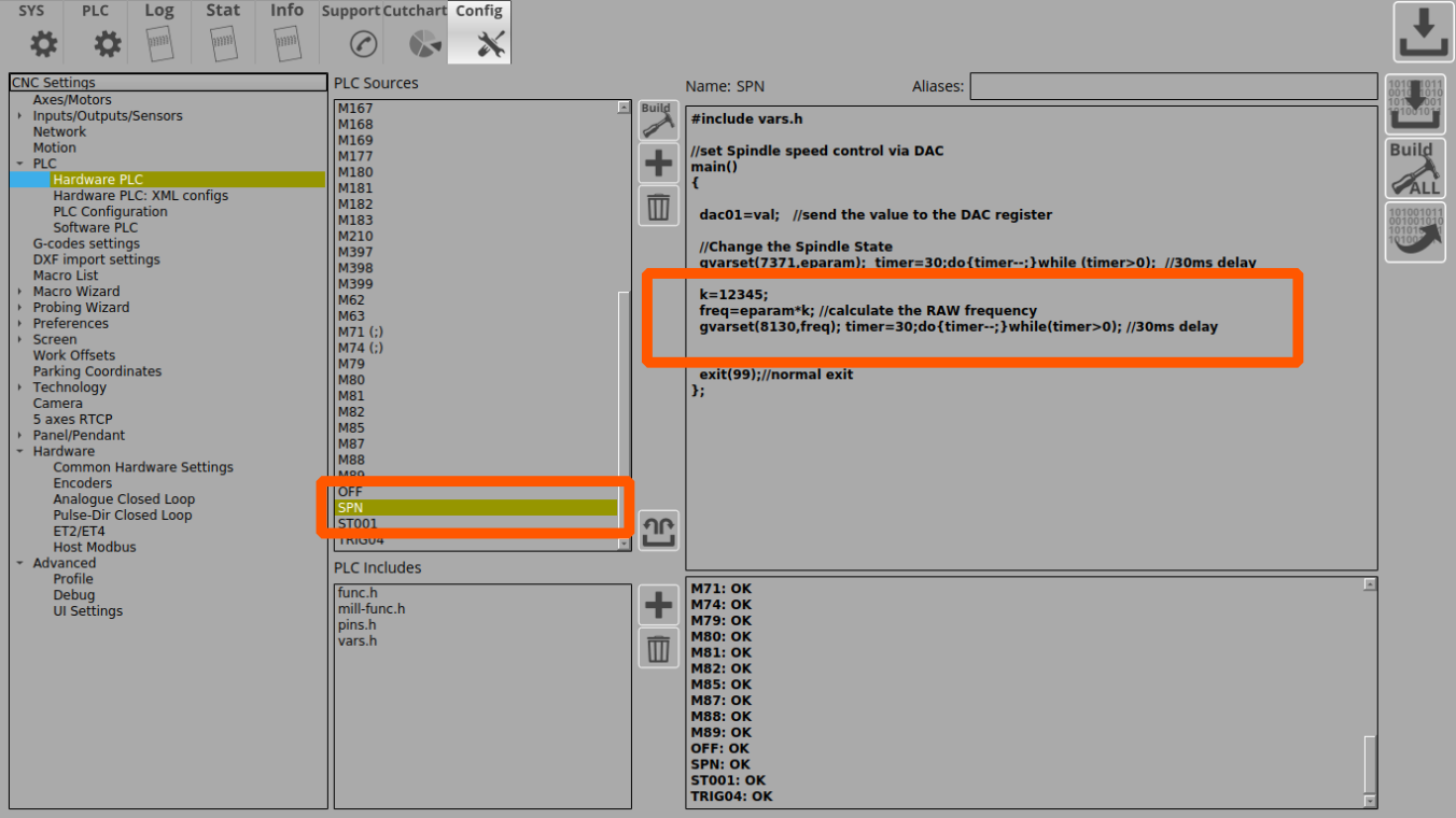
2. Add the following code to to enable the generator into the Hardware PLC spindle speed adjustment procedure (SPN.plc controls the speed with which the spindle is rotating).
  // Set the acceleration of the generator
  gvarset (8131, 100000); timer = 30; do {timer -;} while (timer> 0); // Delay for 30ms

  // Convert reference spindle speed to frequency.
  // The value of the coefficient k is selected in such a way as to convert
  // 12-bit spindle speed to generator frequency
  k = 123456;
  freq = eparam * k; // Calculate the raw value of the generator frequency by using the multiplier k

  // Send the generator frequency value
  gvarset (8130, freq); timer = 30; do {timer -;} while (timer> 0); // Delay for 30ms
  exit (99); // normal exit
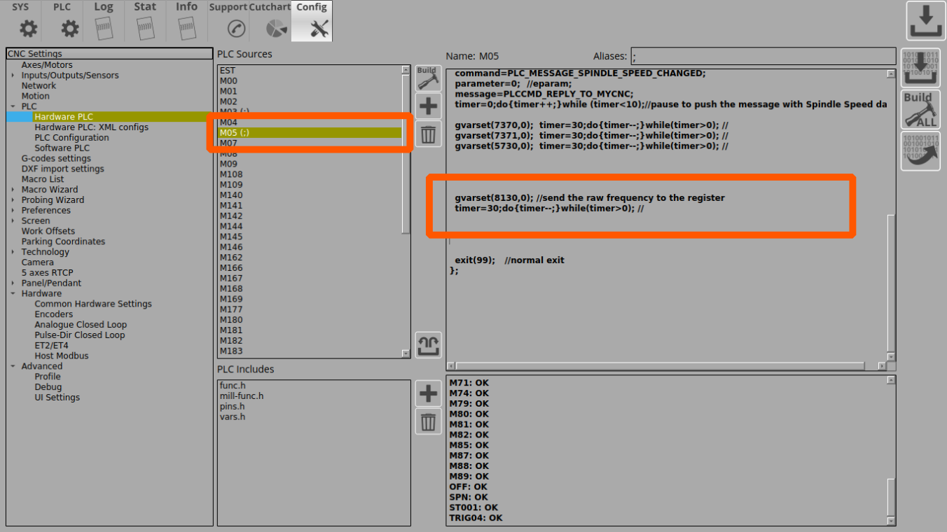
3. Add the generator shutdown code to the Hardware PLC spindle shutdown procedure (M05.plc turns the spindle OFF). It is also convenient to add this code right at the end of the PLC procedure, before the exit(99); line.
  // Send generator frequency value
  gvarset(8130,0); timer = 30; do {timer -;} while (timer> 0); // Delay for 30ms
  exit (99); // normal exit
In this implementation, the pulse-dir generation will be switched ON simultaneously with the classic control (a + 0-10V relay analog output). It is assumed that an unused spindle will be shut off physically by the operator and that the additional control signal will not affect operation.
If the task is to connect both spindles at the same time and switch them during operation
(for example, by referencing their tool number), it is necessary to organize
a more complex PLC procedure, which will be checking the number of the tool,
the value of the global variable or input controller and by this condition
would include only one of the spindles.
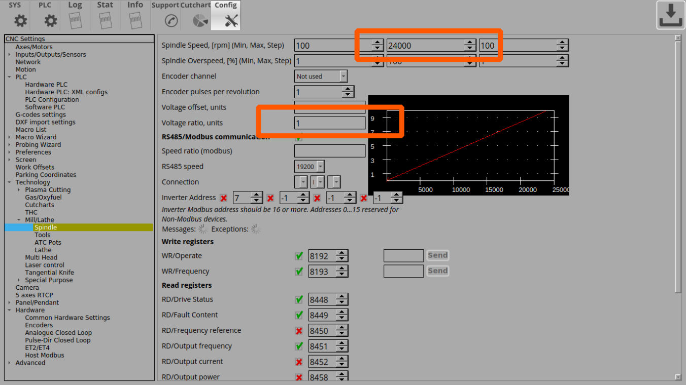
In this example, we are assuming that the speed of a conventional spindle is 24,000 rpm. This value, respectively, is registered as the maximum spindle speed in the settings (Settings > Config > Technology > Mill/Lathe > Spindle).
At this spindle speed, a full 10V signal must be sent to the analog output, so the “voltage ratio” coefficient is set to “1” (in the case of, for example, a spindle with an input signal range of 0-5V, this coefficient would be 0.5 to get a 5V signal at maximum speed).
When calling the PLC procedures for turning ON the spindle (M03.plc) and changing the spindle speed (SPN.plc), the spindle speed value is stored in the eparam variable.
myCNC controllers have 12-bit registers for PWM and DAC at 0-10V.This means that with a maximum spindle speed of 24000 rpm and a factor of 1, the eparam variable will have a maximum value of 4095.
Assume that the maximum servo spindle speed is 4,500 rpm. Then the eparam value at a speed of 4500 rpm will be:
4500 * (4095 ÷ 24000) = 768
The Pulse-Dir input of the servo spindle is set to 10,000 pulses, i.e. the motor shaft will make a full revolution every 10,000 pulses. Then, to achieve a full speed of 4500 rpm, the following pulse rate is required:
10000 * (4500 ÷ 60) = 750 000
The register RAW value for 750kHz (750,000Hz) will therefore be calculated as follows:
750000 ÷ 0.0014549 = 515499347
If the maximum speed corresponds to the eparam value of “768”, then the value of the coefficient to obtain “515499347” will be calculated as follows:
515499347 ÷ 768 = 671223
By setting these values in the M03.plc and SPN.plc procedures, we will generate the required 750 kHz frequency when the spindle speed is set to 4500, as well as smooth frequency control over the entire range from 0 to 4500 rpm.
A method for evaluating the required acceleration of a generator
One unit of the generator acceleration is, by a very rough approximation, 1 impulse / s2. This means that with such an acceleration, the generator “accelerates” to a frequency of 1 Hz in 1 second. If, in our case, the maximum frequency is 750,000, then the acceleration must be equal to the same value in order to “accelerate” to this frequency in 1 second.
Test code for spindle start-up and spindle speed adjustment procedures
- M03.plc
//Turn on Spindle clockwise
#include pins.h
#include vars.h
main()
{
  command=PLC_MESSAGE_SPINDLE_SPEED_CHANGED;
  parameter=eparam;
  message=PLCCMD_REPLY_TO_MYCNC;
  timer=0;do{timer++;}while (timer<10);//pause to push the message with Spindle Speed data

  timer=0;
  proc=plc_proc_spindle;

  val=eparam;
  if (val>0xfff) {val=0xfff;};
  if (val<0) {val=0;};

  dac01=val;

  portclr(OUTPUT_CCW_SPINDLE);
  portset(OUTPUT_SPINDLE);

  gvarset(7370,1);//Spindle State
  timer=30;do{timer--;}while (timer>0); //
  gvarset(7371,eparam);//Spindle Speed Mirror register

  //gvarset(7372,0);//Mist State
  //gvarset(7373,0);//Flood State


  gvarset(8131, 500000); timer=30;do{timer--;}while(timer>0); //30ms delay
  k=671223;
  freq=val*k; //calculate the RAW frequency
  if (freq>515499348) {freq=515499348;};
  gvarset(8130,freq); timer=30;do{timer--;}while(timer>0); //30ms delay


  //delay after the spindle was turned on
  timer=spindle_on_delay;
  do{timer--;}while (timer>0); //delay until the spindle reaches the given speed

  exit(99);	//normal exit
};
- SPN.plc
#include vars.h
//set the Spindle Speed through DAC
main()
{
  val=eparam;
  dac01=val;	//send the value to the DAC register

  //Change the Spindle State
  gvarset(7371,eparam);  timer=30;do{timer--;}while (timer>0);  //30ms delay

  s=gvarget(7370);
  if (s!=0) //if spindle should be ON
  {
    k=671223;
    freq=val*k; //calculate the RAW frequency using the multiplier
    if (freq>515499348) {freq=515499348;};
    gvarset(8130,freq); timer=30;do{timer--;}while(timer>0); //30ms delay
  };
  exit(99);//normal exit
};
Low level CNC registers to control independent pulse generator
This is for records only. Users don't have to utilize these settings which can be altered only by having low-level access to the controller.
| Register Name | Address | Description |
|---|---|---|
| EXT_GENERATOR_SPEED | 225 | Generator Frequency, [units] 1 unit = 0.000736 Hz |
| EXT_GENERATOR_ACCEL | 226 | Generator Acceleration, [units] 1unit = 0.736 1/c2 |
Independent pulse output can be used for -
- Spindle control based on Servo motor and pulse-dir driver
- stepper motor based coolant system.


