Table of Contents
Laser Cutting
(Laser cutting is currently at Development Stage)
Laser cutting control is provided within myCNC software.
The following global variables are often used for laser cutting applications:
| Name | Global variable | Fuction |
|---|---|---|
| 8119 | Setting up the PWM frequency to control modulation. For example, gvarset(8119,2000); sets frequency to 2kHz. NOTE: Must be set from Hardware PLC! | |
| GVAR_FOCUS_SET_ZERO | 8502 | Set zero for the focus axis |
| GVAR_FOCUS_SET_MAX_POS | 8503 | Set maximum position for the focus axis |
| GVAR_FOCUS_SET_MIN_POS | 8504 | Set minimum position for the focus axis |
| GVAR_FOCUS_HARDLIMITS | 8505 | Set hardware limit port number for focus axis |
| GVAR_AXPLUS_SET_ZERO | 8522 | Set zero for AxisPlus |
| GVAR_AXPLUS_SET_MAX_POS | 8523 | Set maximum position for AxisPlus |
| GVAR_AXPLUS_SET_MIN_POS | 8524 | Set minimum position for AxisPlus |
| GVAR_AXPLUS_HARDLIMITS | 8525 | Set hardware limit port number for AxisPlus |
For more info on Global Variables in general, please consult this manual.
Notes:
- Writing to MAX_POS for either Focus or AxisPlus resets the current working position to 0, and sets the upper limit with the offset specified in the parameter (in pulses).
- If, for example, the number of pulses per unit is 5000, then
gvarset(8523, 10000);will set the program coordinate to be 0, and the machine zero will put 10000 pulses (i.e. 2 units) above the current position. Therefore, in this example, the current machine coordinate will be “-2”
- For the HARDLIMITS for either Focus or AxisPlus, the low byte contains the negative limit port number, and the high byte contains the positive limit port number. The value can range from 0 to 255.
- By default, these limit port numbers should typically be taken from the myCNC control system settings (in Config); they should be redefined via the global variables from a PLC only in certain special applications.
Writing a value to the Global variable register from Hardware PLC procedure will change Frequency of PWM outputs. This option is available for special edition of the myCNC-ET7 control board.
gvarset(8119,2000); //set frequency to 2kHz
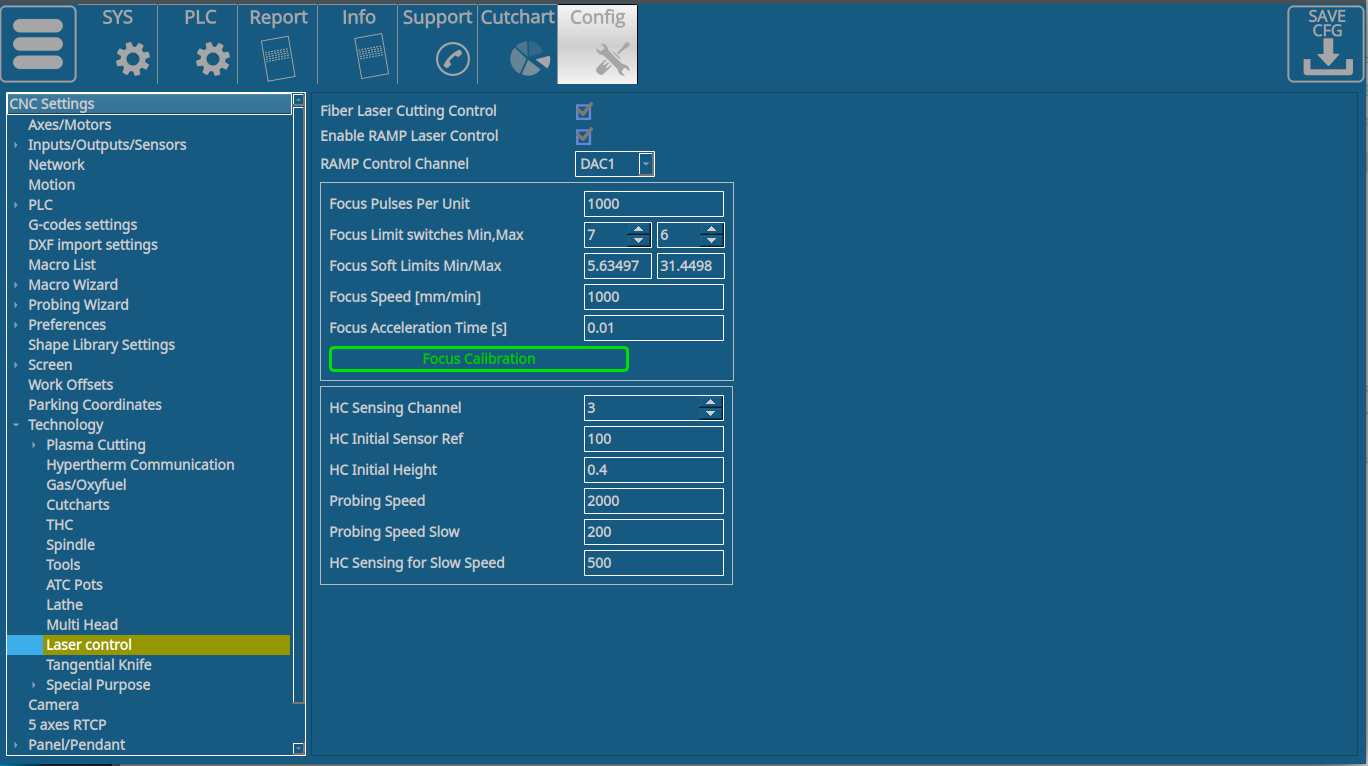
The Laser Control settings window (Settings → Config → Technology → Laser control) allows for fine laser control at different speeds. This allows to prevent overheating when approaching corners, etc:
The following settings are available:
- Enable/disable toggle
- Min/Max control values. This allows the user to set values from 0 to 99 percent of the total laser power.
- Speed ranges for min/max values set the speeds range in which the laser power will be changed between the two values set above (everything below the min speed value will be at min control value, everything above the max speed value will be at max control value, and in the range in-between the two speed values there will be a linear transition between the two control values).
- PWM channel to specify the channel designated for laser control
- Focus pulses per unit
- Focus limit switches for the MIN/MAX limit - input numbers
- Focus software limits
- Focus speed and acceleration
- Height Control ADC sensing channel
- HC Initial Sensor Ref to specify the “initial” coordinate that is assigned to a specific Initial Height (i.e. when the sensor readings are equal to the Initial Sensor Ref, the Height is set to be the initial height - typically a value that's close to zero as to increase precision).
- HC Initial Height - the height value that's set when a sensor reading is equal to the Initial Sensor Ref
- Probing speed and Probing Speed Slow (probing speed slows down as the point of “contact” is approached)
- HC Sensing for slow speed - the value of the sensor to enable slow probing speed
Laser cutting profile
The myCNC Team provides the experimental laser cutting profile Y1366L on request. Note that at the time of writing the manual (November 2021) the profile is currently under development and is not yet intended for final release.
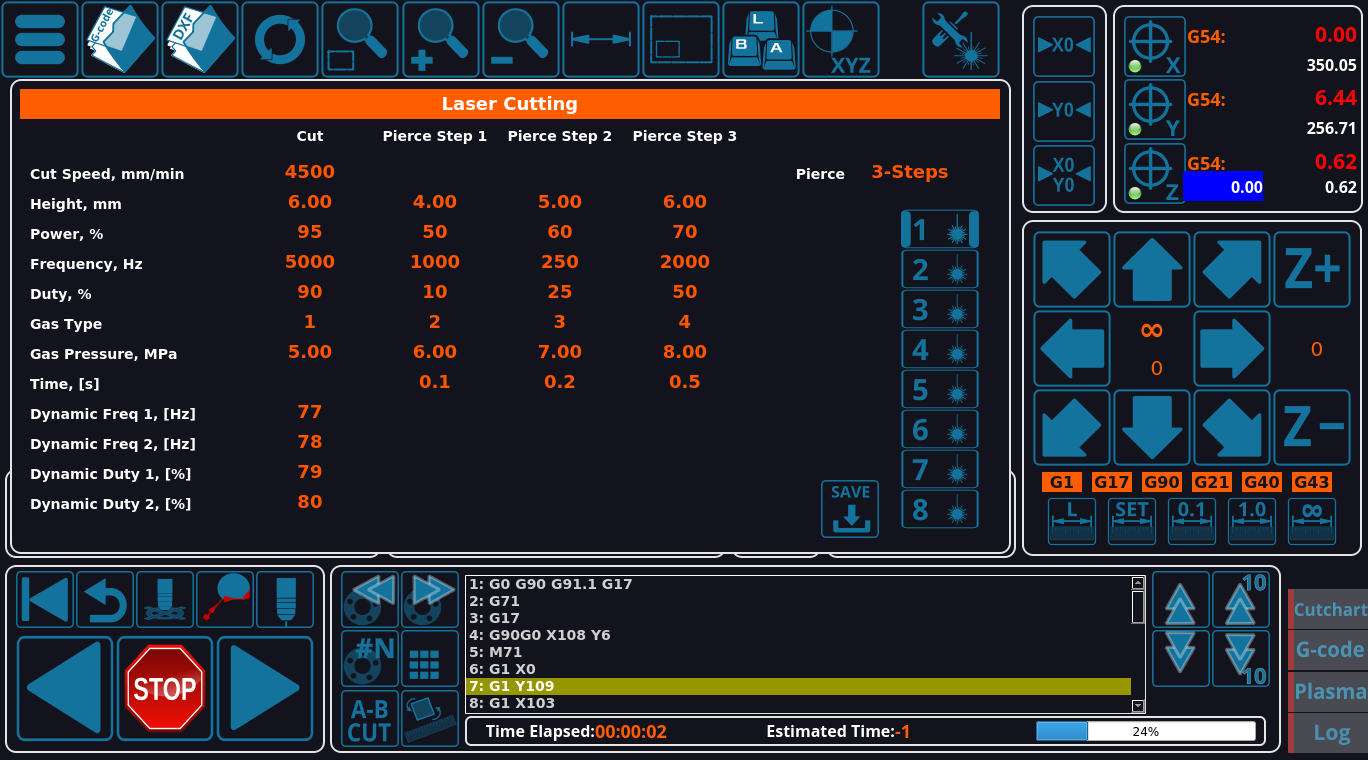
The main profile screen is displayed below:
The profile allows to select the following:
- Cut speed
- Height
- Power (percentage)
- Frequency
- Duty
- Gas Type, Gas Pressure
- Time
- Dynamic Frequency, 1 and 2
The profile also allows to use up to three pierce steps, and store up to 8 presets for laser cutting.
The modes can also be switched using the G130 command, for example:
G130 P1
G130 P2
The profile utilizes the following global variables:
| GVAR_LASER_PRESET_SELECT | 8470 | Load a set of parameters for the corresponding preset number |
| GVAR_LASER_PRESET_SAVE | 8471 | Save the current parameters as a cutting preset for the specified number |
DXF Import
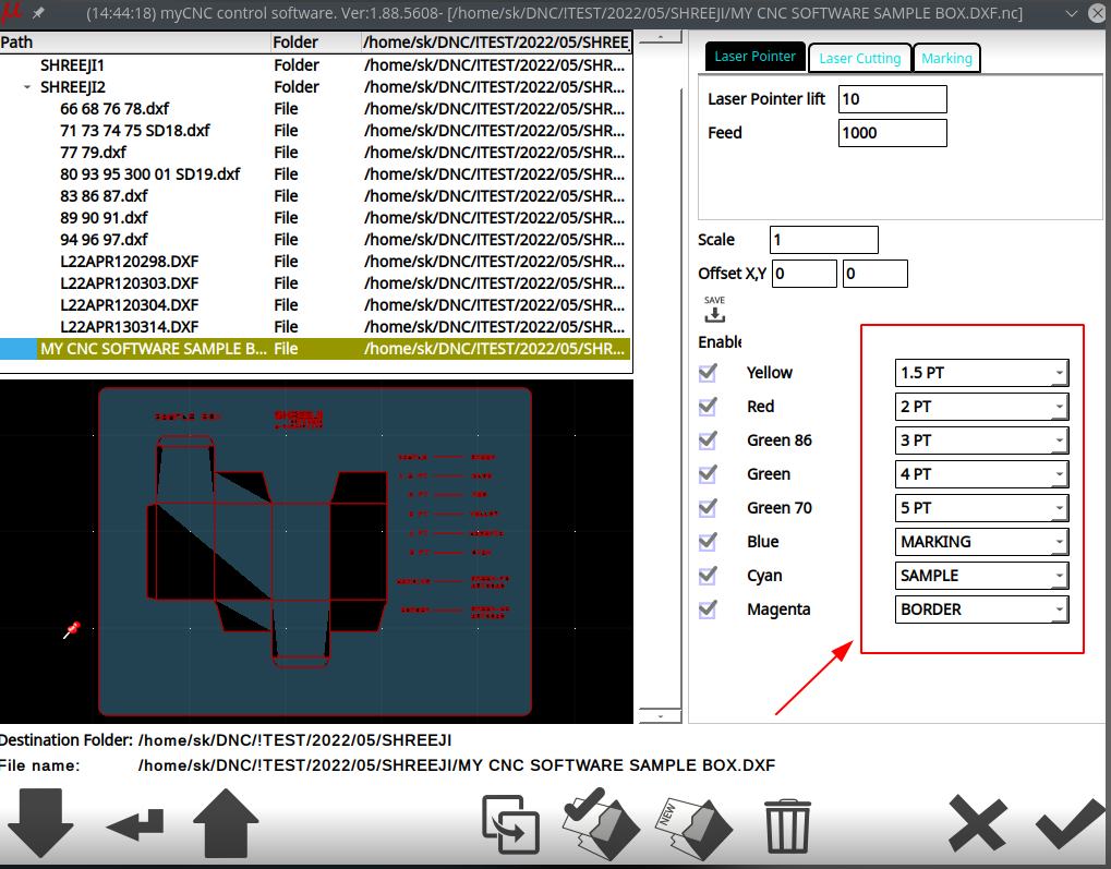
It is possible to enable a special laser cutting mode for DXF import, that switches the typical tools (such as knives, marker/pen, etc) into laser cutting modes for die board cutting. In order to do so, go into Settings > Config > Technology > Laser control, and enable Die Board Cutting:
As a result, the modes will be available for selection at the DXF Import screen:
To read more about general DXF import settings, please consult the following manual: Importing DXF files into myCNC
Calibration
For the Height (H) axis to work, a calibration process is required. This allows the system to determine the relationship between the height sensor reading and the actual torch height.
The calibration process is implemented in the M275 PLC procedure.
The procedure consists of the following steps:
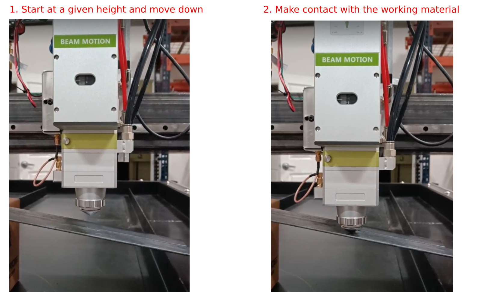
- The laser torch moves down until it touches the sheet,
- At the point of contact, the system resets the height coordinate to 0,
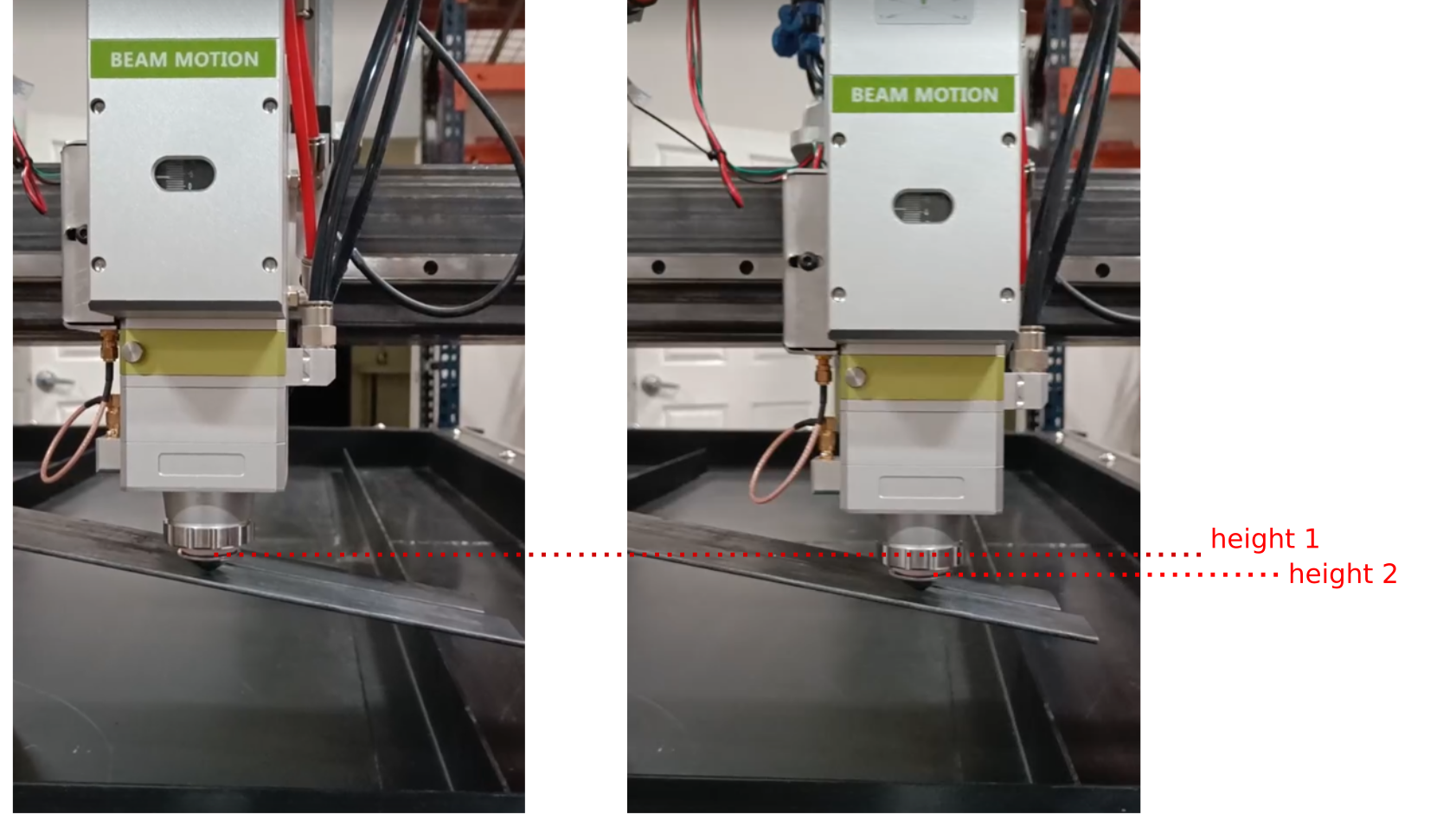
- The system starts moving upward and registers the reading of the height sensor and the real H coordinate relative to the sheet at the same time.
The process is also shown in the images below:
- Start at the top, move down until contact is made:
- Begin moving up while compiling a log, correlating the readings of the height sensor and the real coordinate H.
- This will then allow the system to perform height control. In the image below, the value of Height 1 and Height 2 is different, however the readings of the height sensor are the same due to the same proximity to the metal:
The code for the calibration procedure is shown below:
- M275.plc
#include vars.h
#include pins.h


do_laser_probing()
{

  gvarset(8341,500); //AxisPlus Jog Speed 100mm/min
  gvarset(8342,5); //AxisPlus Jog Accel Time 0.005sec

  timer=0;
  slow=0;

  gvarset(8340,0-1); //AxisPlus Jog Negative Direction

  do{

  a=gvarget(7203);

  if (slow==0)
  {
    if (a<800)
    {
      gvarset(8341,50); //AxisPlus Jog Speed 100mm/min
      gvarset(8340,0-1); //AxisPlus Jog Negative Direction
      slow=1;
    };
  };

  if (a<16)
  {
    timer=200000;
  };

  timer++;

  }while(timer<100000);

  gvarset(8342,5); //AxisPlus Jog Accel Time 0.002sec
  gvarset(8340,0); //AxisPlus Jog Stop

  timer=0;
  do
   {
      a=gvarget(8332);
      timer++;
   }while(a!=0);

  pwm02=timer;

  gvarset(9717,0); //Set machine coordinate for AxisPlus to 0

  timer=10; do { timer--; }while(time>0);


};

do_laser_calibration()
{
  gvarset(5740,999); //clear calibration (if any exists)
  timer=10; do { timer--; }while(time>0);

  timer=200; do { timer--; }while(time>0);


  timer=0;

  gvarset(5539,1);
  gvarset(8330,100); //Speed
  gvarset(8331,500); //Accel Time
  g0moveA(0x0,0x80,3000);//Axis Plus
  do
   {
      a=gvarget(8332); //obtain the state of AxisPlus (can be idle, G0, jog, etc)
      timer++;
      if ((timer&0xf)==0)
      {
        gvarset(5731,0); //Save Position Log Every 32ms
      };
   }while(a!=0);


  gvarset(5740,998); //save calibration
  timer=10; do { timer--; }while(time>0);


};


main()
{

  gvarset(8030,0);     //THC Deactivate

  do_laser_probing();
  do_laser_calibration();

  exit(99);
};
Homing
Homing for the Height (H) axis
The process for the homing of the H-axis consists of the following steps:
- Disable Hardware Limits
- Reset software limits
- Enable IHC Stage #2
- Switch to fast g0moveA implementation
- Jog in the positive Z direction (using axis H) while monitoring the homing sensor input until it's engaged
- Once the sensor has been triggered, move away from the sensor at a slow speed until it's released.
- Record the position where the sensor was released as 0
- Sent a new minimum coordinate for the H axis
The homing for the H axis (also known as AxisPlus) is available via the M133 Hardware PLC command:
- M133.plc
#include pins.h

main()
{

  gvarset(5521,1); //Ignore Hard Limits
  gvarset(8522,999999); //Reset Soft Limits

  gvarset(8048,2); timer=30;do{timer--;}while(timer>0);
  gvarset(5539,1);

  speed=gvarget(8044);

  gvarset(8341,speed); //Set Jog Speed
  gvarset(8342,30); //Set Jog Acceleration time 80ms = 0.08s

  gvarset(8340,1);	//Jog Z+
  do  {  sens=portget(INPUT_HOME_Z);  }while(sens==0);

  speed=speed>>2; //lower speed by a factor of 4
  gvarset(8341,speed); //Set Jog Speed
  gvarset(8342,5); //Set Jog Acceleration time
  gvarset(8340,0-1);	//Jog Z-, Slow speed

  do {  sens=portget(INPUT_HOME_Z);  }while(sens!=0);


  gvarset(8340,0);
  timer=20;do{timer--;}while(timer>0);


  gvarset(8523,0);
  gvarset(8522,0); //Set 0
  timer=20;do{timer--;}while(timer>0);
  gvarset(8524,0-6000); //Set Min Coordinate to "-6" inch

  exit(99);
};
Homing for the Focus (F) axis
The code for F axis homing is shown below:
- M352.plc
// ##### Laser Focus Homing ########

main()
{

  gvarset(8492, 2000); //250mm/min speed (Focus)
  gvarset(8493, 1);   //0.001 Jog acceleration time (Focus)
  gvarset(8495, 1);   //0.001 G0 acceleration time (Focus)

  gvarset(8502,999999); //reset soft limits

  gvarset(8494, 1000); //300mm/min Jog speed (Focus)
  gvarset(8498, 1);   //Jog cmd (Focus) Positive
  do   {   a=gvarget(8499);  }while(a!=0); //wait stop
  gvarset(8503,0); //set Max Soft LImit
  timer=200;do{timer--;}while(timer>0); //PAUSE to show the LED

  //timer=1000;do{timer--;}while(timer>0);

  gvarset(8498, 0-1);   //Jog cmd (Focus) Negative
  do   {   a=gvarget(8499);  }while(a!=0); //wait stop
  gvarset(8504,0); //Set Min Soft Limit
  timer=200;do{timer--;}while(timer>0); //PAUSE to show the LED

  gvarset(8502,0-11000); //Set Coordinate
  //gvarset(8502,0-10000); //Set Coordinate

  //gvarset(8498, 1);   //Jog cmd (Focus)
  //timer=510;do{timer--;}while(timer>0);
 // gvarset(8498, 0);   //Jog cmd (Focus) Negative
  //do   {   a=gvarget(8499);  }while(a!=0); //wait stop


  g0moveA(0x1,0x100,0);
  do{ a=gvarget(8499);}while(a!=0);


  exit(99);

};
Examples of laser cutting setups
An example of myCNC controller being used on a laser cutting setup can be seen below:

