Table of Contents
Setting up the myCNC control board
This is the general setup process for myCNC control boards. Please consult the manuals for specific boards on pinout configurations, etc. A number of general questions that may arise during initial setup are answered in the FAQ section of the documentation wiki.
Power and Network
- Connect 24V DC power supply to myCNC control board
- Connect myCNC Ethernet controller with Network cable directly to Host computer or to Network Router. If use Odroid-C2 (Raspberry-Pi3) computers as a Host, Network cable is a short 0.5ft cable between Odroid & Controller

- Setup Network addresses for Host computer and myCNC Ethernet controller. Addresses of Controller and Host should be in same local network. For Example -
Controller Address: 192.168.4.78
Host Address: 192.168.4.100
or
Controller Address: 192.168.5.10
Host Address: 192.168.5.11
Look here if need to change IP address of controller board
- Goto MyCNC software, Cfg Settings, Network Tab and
- Set actual Controller IP address to “Controller IP Address” to tell the software where it can find myCNC Controller,
- Set “Network Protocol” to “UDP”,
- press “Save” button on the top-right of myCNC screen.
- Changes should be applied on the fly and UDP message counter should start counting which means communication between Controller & Host works correct.

- More information on network settings is available in the QuickStart Network Setup manual.


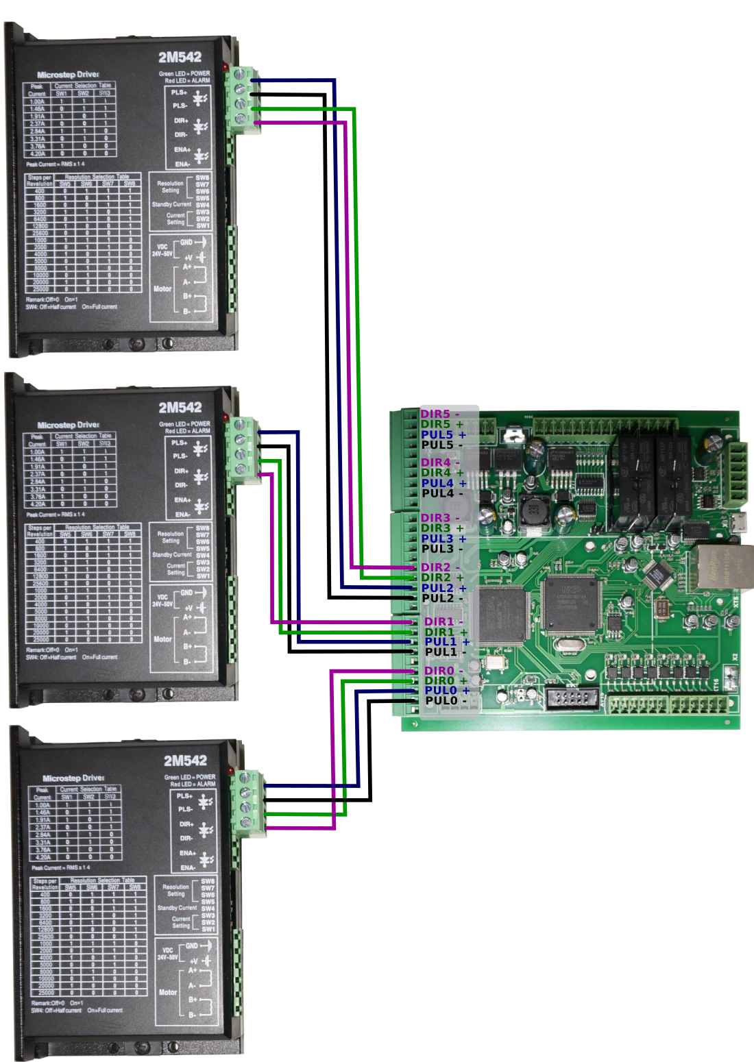
Stepper Drivers
- Connect Pulse-Dir signals from servo or stepper driver to myCNC control board

Spindle and Plasma Cutter connection
The commands such as M03 (turn spindle ON) and M71 (turn plasma cutter ON) are written with some specified input and output numbers in mind - when the signal is sent to that particular output, or when an input state is changed, an action occurs. However, the particular numbers for these inputs and outputs are not specified in the particular PLC procedures, but rather referred to (for example, a change in some output which is defines as OUT_SPINDLE will change the spindle state from OFF to ON). This is done so that it is not necessary to go through all the relevant PLC procedures when an input needs to be changed. Instead, these inputs are define in the pins.h file (Settings > Config > PLC > Hardware PLC > pins.h). When setting up the board, consult the pins.h file to check which input/output is assigned to what action:

Pulse Width
- Check what minimal pulse width your drivers accept and set pulse width of myCNC control board accordingly (equal or more) in MyCNC software → Cfg Settings → Hardware Tab → Common Hardware Settings
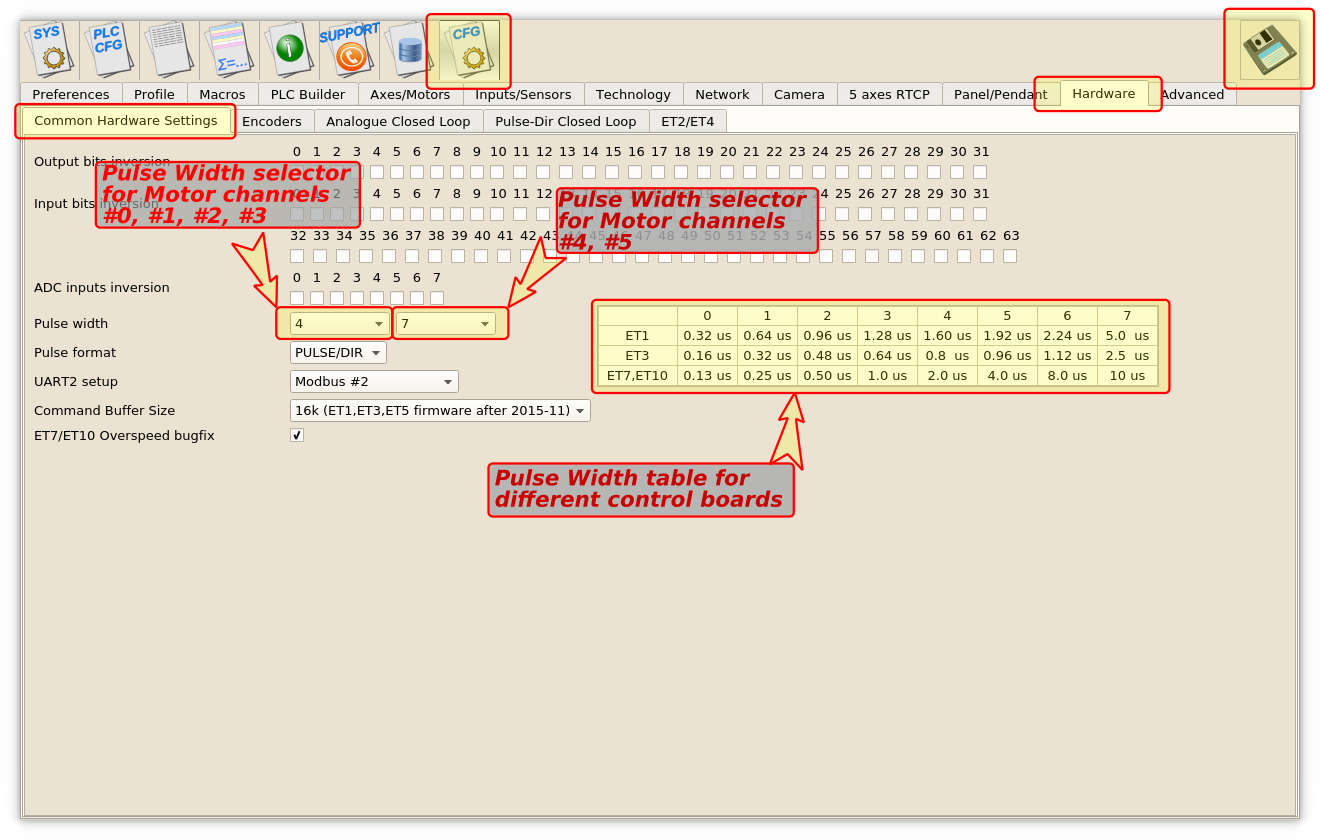 MyCNC-ET6, myCNC-ET7 controllers support separate pulse width settings for the first 4 channels (#0, #1, #2, #3) and the rest 2 (#4, #5). This option can be convenient if use high performance servo drivers with low psed stepper drivers (for example high speed servos for X, Y, Z axes and low speed stepper for rotational A axis). myCNC-ET10 controller use only the first pulse width selector for all motor outputs.
- Read more about the pulse width setup here.
