Table of Contents
MyCNC Plasma Setup Example (X1366P)
NOTE: The myCNC team recommends utilizing the examples provided in this manual (as well as other manuals in this documentation) as a starting point for your machine setup. When possible (and applicable), it is recommended to keep changes to a mininum. In general, using these examples as the basis for your PLCs/macro commands allows for an easier setup process.
In order to familiarize yourself with the layout and main functions of the X1366P profile screen, please consult the Plasma cutting profile 1366P screen description manual.
THC manual available here: Torch Height Control (THC)
In this article, we will show an ET7 control board connection example and the software configuration required to build a typical Middle-Class plasma cutting table. The Cutting table is supposed to have:
- Torch Height control (THC) with Z height control through a standard Z axis (no matter whether it is a stepper or a servo),
- Initial Height Control (IHC) - Probe sensor and ability to find material by lowering a Torch and searching material sheet by probing.
- (Optional) Oxyfuel gas cutting torch control (Oxy Heat low/high pressure valves, Oxy Cutting high/low pressure valves, Gas valve, Ignition valve/relay)
- (Optional) Drill head - Lowering Drill valve, Drill ON relay
- (Optional) Mechanical (or Pneumatic) Scriber to perform marking (etching) operations.
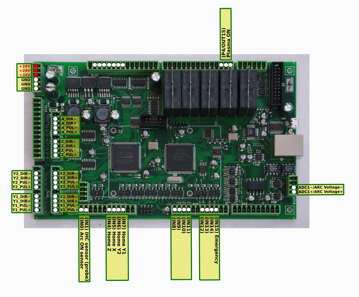
Below is the pin diagram for the myCNC-ET7 board which will be used in this example:
Power supply connection
Connect 24V DC power supply to the +24V and GND contacts:
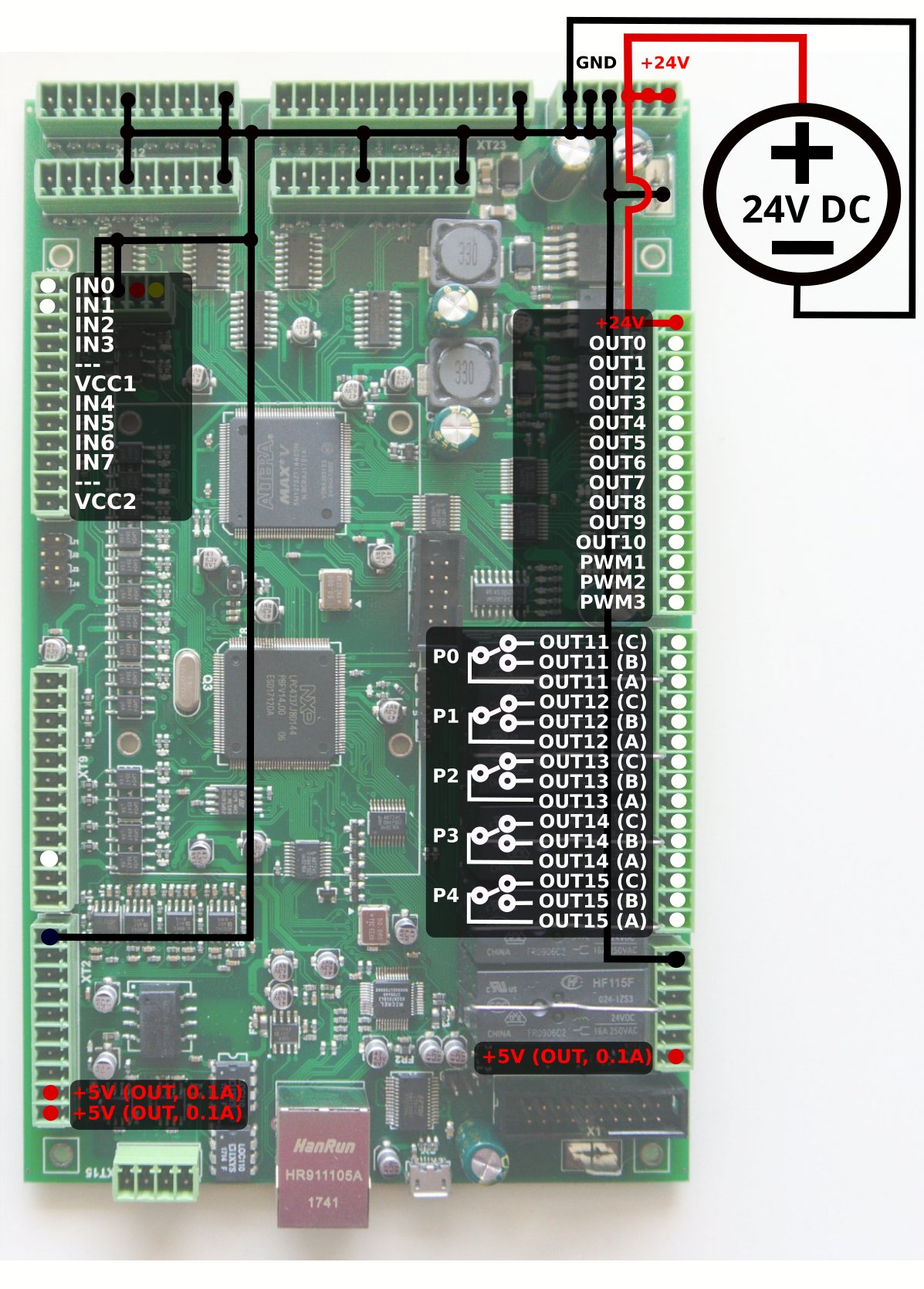
Pulse-Dir connection and configuration
Connect pulse-dir outputs according to the first pinout diagram (shown above).
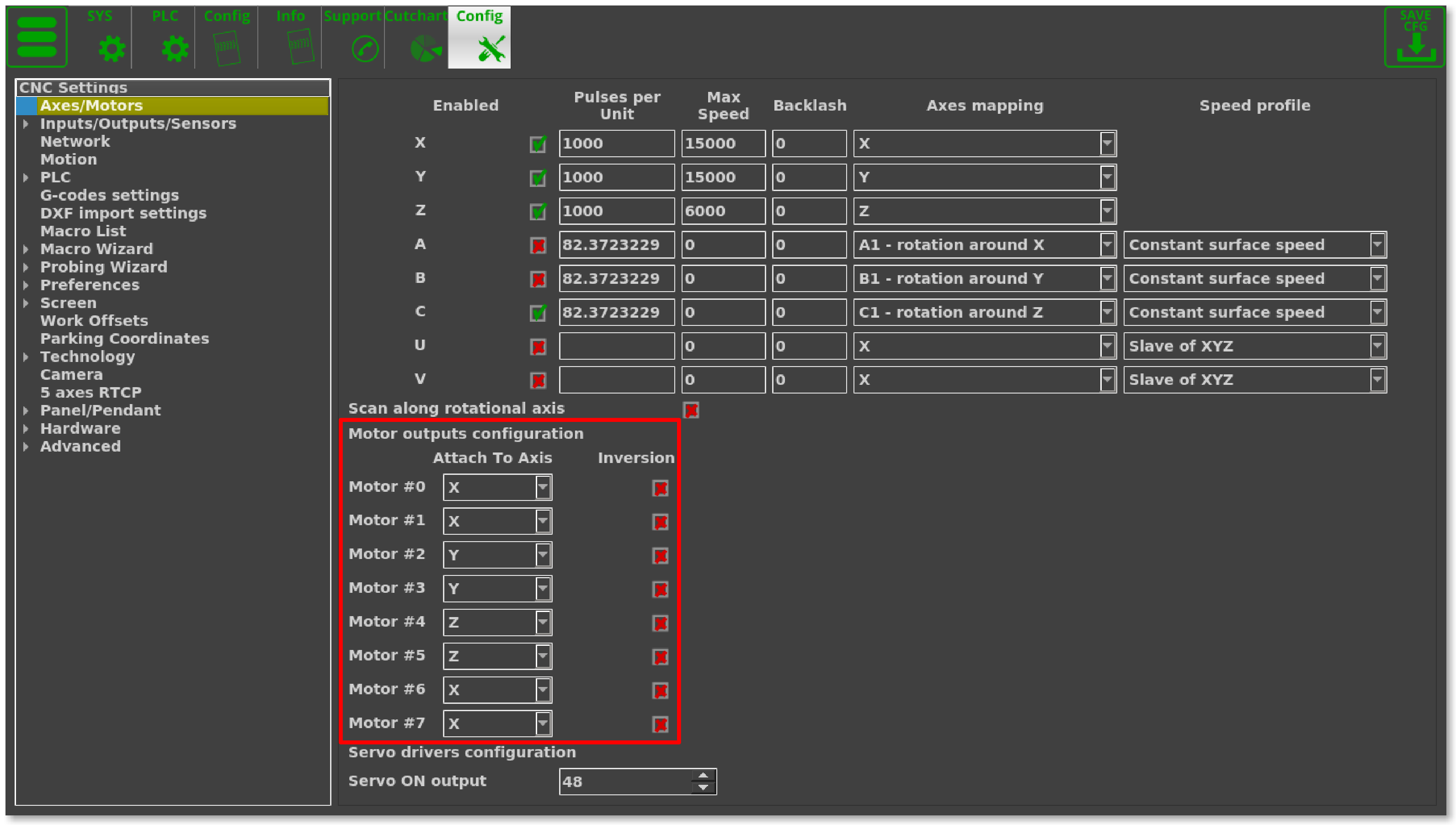
Connection is configured to use dual motors for X and Y axes. Leave motor output unconnected if you have only 1 motor for X or Y axes.
The settings for motor axes configuration can be found by going into Settings > Config > Axes/Motors (read more here). These will be unique for each user depending on how the motors are set up:
Inputs connection
Arc Transfer, IHC sensors
More information on IHC is available in the IHC (Initial Height Control) manual.
In a typical configuration:
- IN0 - Arc Transfer (Arc ON) Sensor from the plasma power source.
- IN1 - Initial Height Control (IHC) Sensor or Probe Sensor - a sensor which triggered when the torch touches the material sheet.
Both inputs should be configured in PLC Builder, in the pins.h file which can be accessed by going to Settings > Config > PLC > Hardware PLC. Either of these can also be re-assigned to other input pins, 0 and 1 have simply been chosen out of convenience to have a default set of connections:
#define INPUT_ARC	0
#define INPUT_IHC	1
A video explaining the pins.h file is available here:
Home Sensors
The inputs for the homing sensors are similarly configured in the pins.h file (Settings > Config > PLC > Hardware PLC).
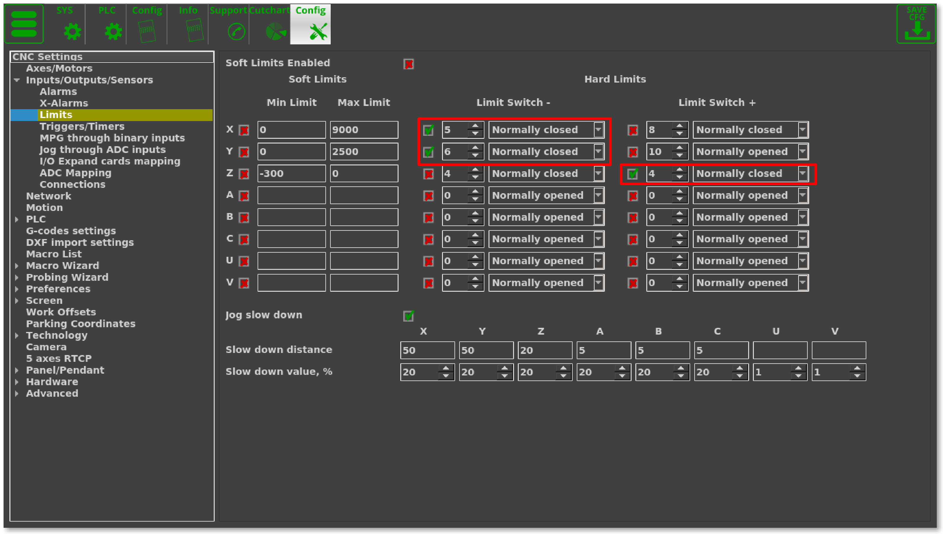
Additionally, the inputs should also be configured in “Inputs/Sensors” - “Limits” settings dialog if Home sensors are used as Limit Switches as well. If Home sensors are used as Limit switches similar to the on the table below,
| Input Number | Home Sensor | Limit Switch |
|---|---|---|
| IN6 | Y1 | -Y |
| IN5 | X | -X |
| IN4 | Z | +Z |
then the settings for setting up those limit switches will be done in the following manner:
If Limit switchers have been configured and if any of them have been activated, the currently running job will be stopped and an error message will be displayed in the centre of the main screen.
Homing Macros
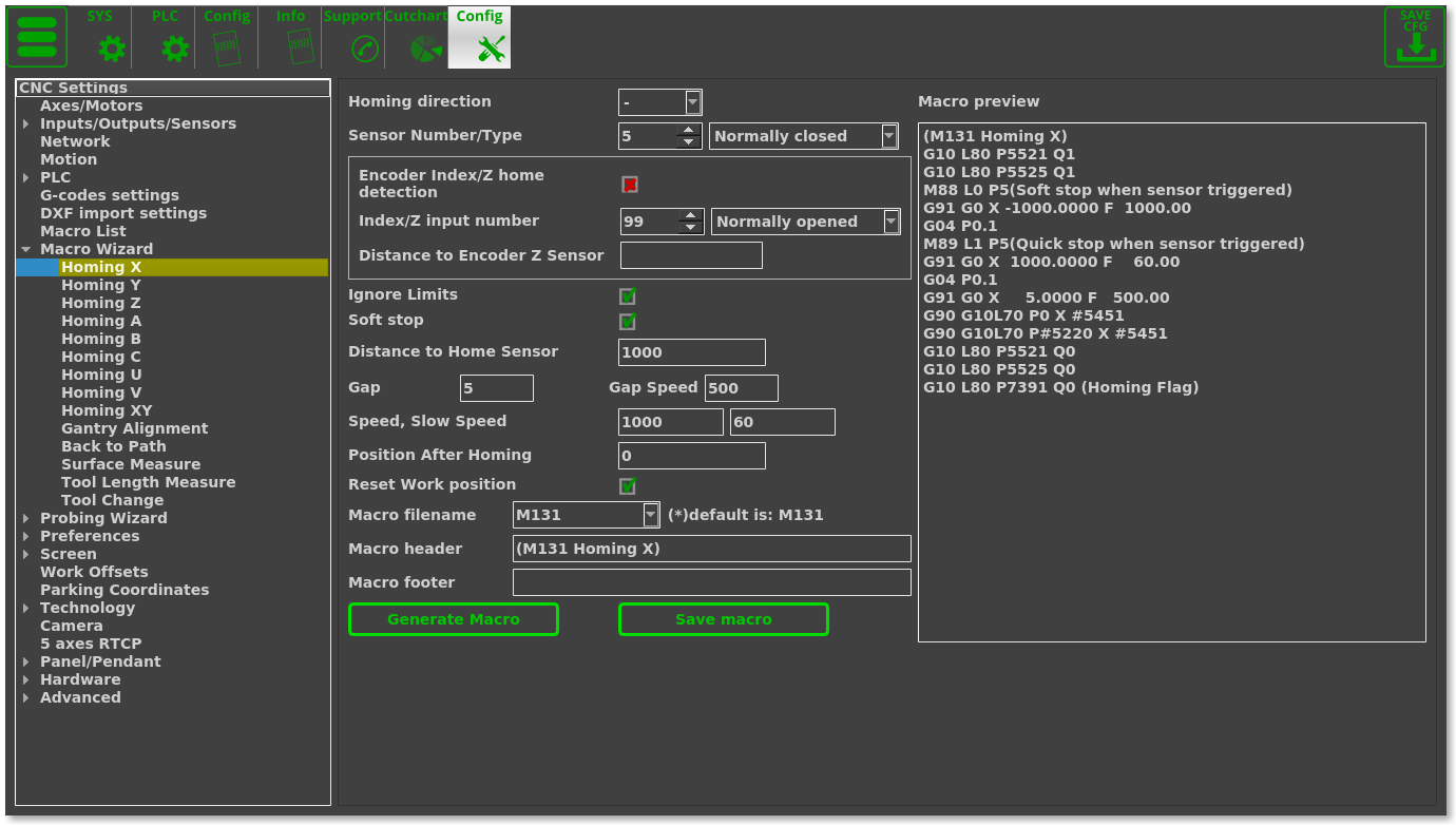
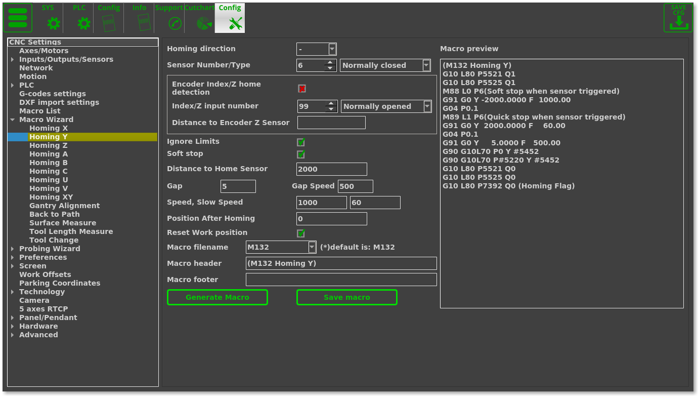
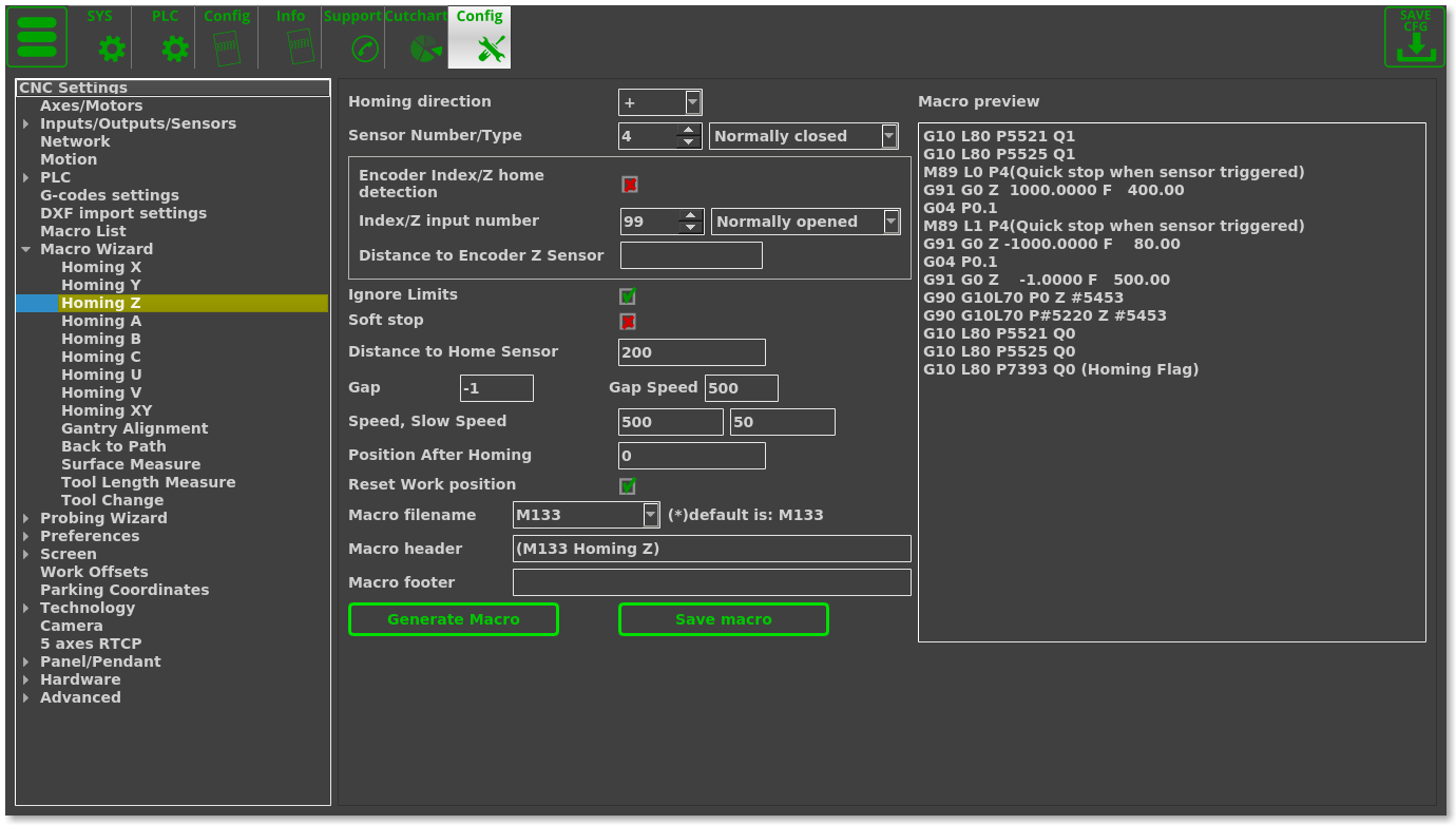
Home sensor numbers should be configured in the Macro Wizard accordingly and the Homing procedures for the X, Y, Z axes must be generated. You can read more on the homing procedure here.
- Change the necessary settings (if required) in the Macro Wizard for Axis X
- Press Generate to generate the Homing X macro in the “macro preview” window, check the generated code
- Press Save Macro to save the Homing X macro to the M131 file on the disk
- Change any necessary settings in the Macro Wizard for Axis Y
- Press Generate to generate the Homing Y macro in the “macro preview” window, check the generated code
- Press Save Macro to save the Homing Y macro to the M132 file on the disk
- Change any necessary settings in the Macro Wizard for Axis Z
- Press Generate to generate the Homing Z macro in the “macro preview” window, check the generated code
- Press Save Macro to save the Homing Z macro to the M133 file on the disk.
Emergency Stop button
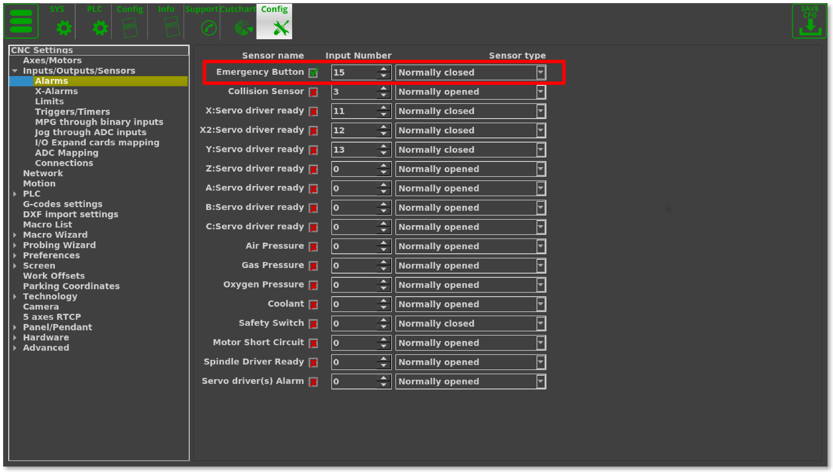
Typically, Input #15 (IN15) is utilized as the emergency stop button (this, like the other inputs, can be re-configured).
An emergency stop should be set up in the Alarms configuration dialog (Settings > Config > Inputs/Outputs/Sensors > Alarms). Such an emergency button setup is shown below:
If the emergency stop button is pressed, the current job (current running process) will be stopped, and any new runs be blocked. In such an event, an alarm message will be displayed on the main screen.
Job Start/Stop buttons
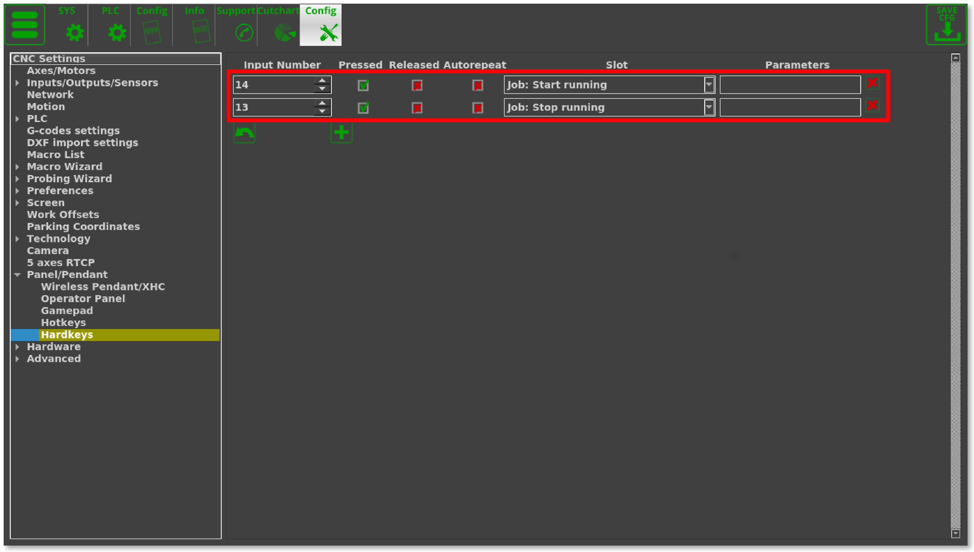
Inputs can be used as Hot Keys. Binary inputs IN14 and IN13 can be configured as “Start” and “Stop” keys in the Settings > Config > Panel/Pendant > Hardkeys configuration dialog. See the inputs configuration in the picture below. To configure additional hot keys, press the “+” button, select an input number that is not yet in use, select the “Pressed” checkbox and choose the following Slots:
- “Job: Start running” - for Start button
- “Job: Stop running” - for Stop button
Outputs
Plasma ON
Plasma On signal is utilized to turn ON the plasma power source. Relay output or Open Collector output can be used as Plasma ON output. In this profile, two outputs are reserved by default (open collector OUT0 and relay output P4 to generate the Power ON signal to the plasma power source.
Output pin number for the plasma power source should also be defined in the PLC Builder, in the pins.h file (found in going into Settings > Config > PLC > Hardware PLC).
- pins.h
#define OUTPUT_PLASMA 0
Scriber
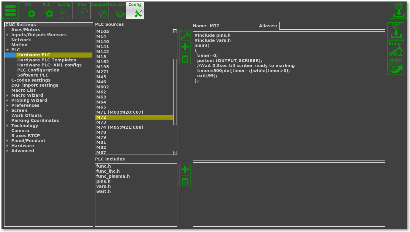
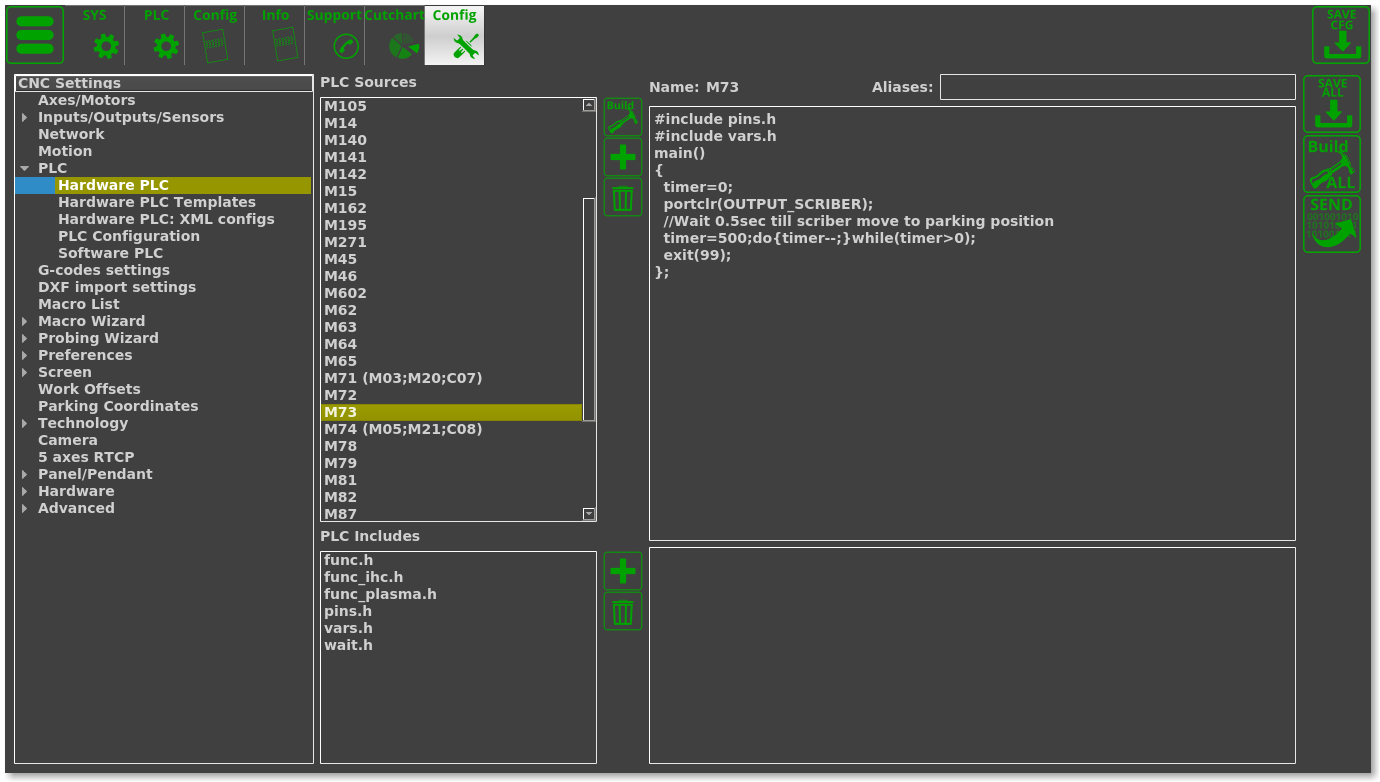
Optional Scriber can be used for marking operations. The scriber is turned ON by the M72 code and turned off by M73. PLC procedures M72.plc and M73.plc are already implemented in the profile to handle the on-off operation for the scriber. We use the OUT13 (relay P2) output to control the scriber.
The output pin for the Scriber should be defined in the pins.h file (Settings > Config > PLC > Hardware PLC > pins.h)
- pins.h
#define OUTPUT_SCRIBER 14
PLC procedure to turn scriber marking ON is M72.plc:
- M72.plc
#include pins.h
#include vars.h
main()
{
  timer=0;
  portset (OUTPUT_SCRIBER);
  //Wait 0.5sec till scriber ready to marking
  timer=500;do{timer--;}while(timer>0);
  exit(99);
};
PLC procedure to turn scriber marking OFF is M73.plc
THC
Arc Voltage
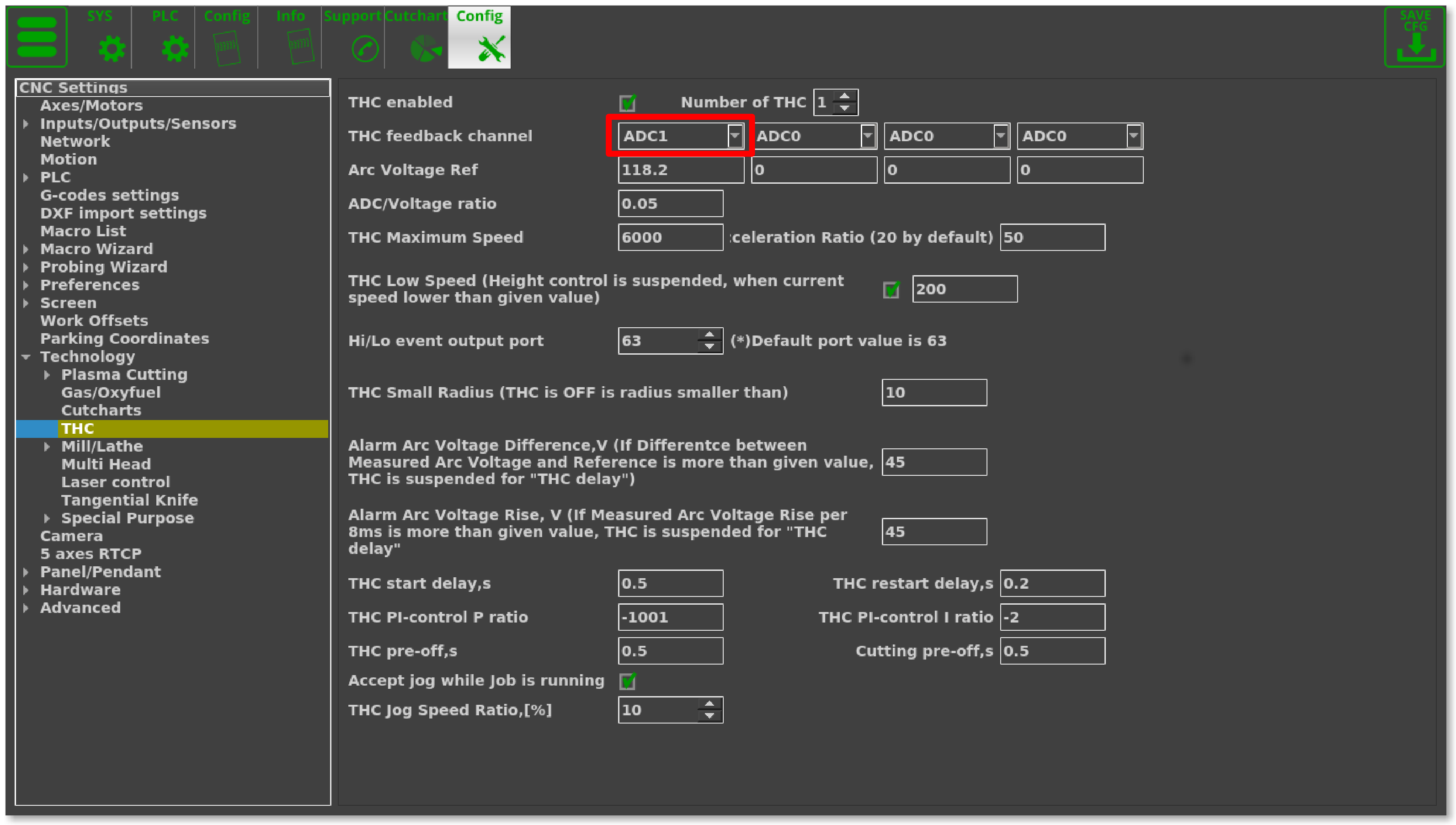
Arc Voltage from Arc voltage divider is connected to the ADC1 galvanic isolated input which is shown in the first diagram (top of the page).
ADC1 channel should be configured as THC#1 feedback channel (THC#2…THC4 are reserved for Multi-Head Gas cutting machines, which are more rarely used).
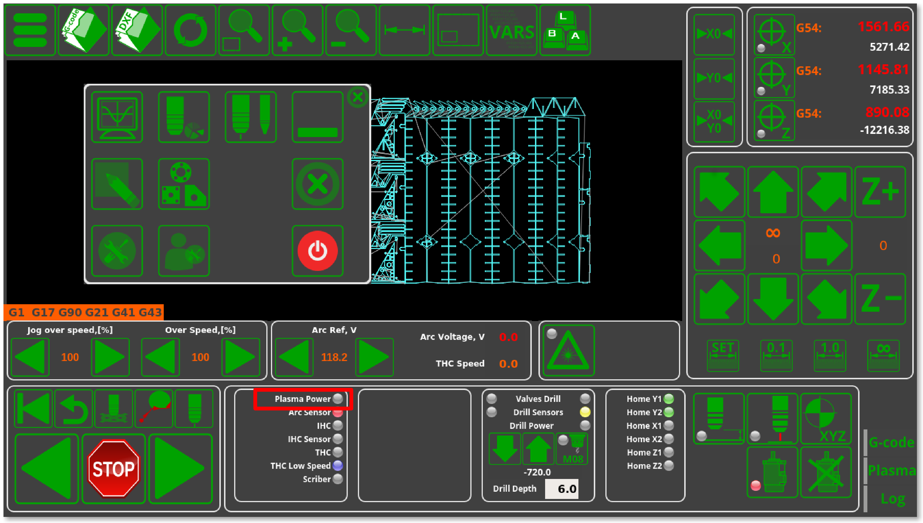
These are the parameters to monitor for the THC process on the main screen:
- Arc Ref - Reference Voltage for THC. THC measures actual Arc Voltage and controls torch height up and down to keep Arc Voltage equal to Reference Voltage. The reference voltage is specified in Global Variable #7011. Reference voltage can be setup:
- Manually on the main screen by operator
- From G-code
- loaded from Cutcharts
- THC can measure actual Arc voltage just after the pierce process has finished and use that arc voltage as a Reference.
- Arc Voltage - actual measured arc voltage (that's ADC#1 in our example).
- ADC/Voltage Ratio
- On the latest versions of the ET7 board, there are 2 galvaniсally isolated ADC inputs with different input voltage ranges - namely, 5V and 12V (instead of 2 12V inputs on earlier board versions). In most cases the 5V input and a 1:50 voltage divider are used.
- That is, in perfect conditions, when 250V are supplied to the input, the voltage divider will divide this value by 50
- 5V at the input supplies the maximum signal, which the ADC then converts to a digital signal (with max value of 4095 for 12bit ADC)
- Meanwhile, the coefficient is used to display the real voltage on the myCNC software screen. This requires to convert the digital value (4095) to 250V by using a coefficient (in our case, a coefficient of 250/4095 = 0.061). Naturally, this coefficient only works for perfectly accurate components with exactly a 1:50 voltage divider, 5V input, etc. Realistically, this value can have a spread of about 20%.
- To see some examples of setting up the coefficient, please consult the full Torch Height Control (THC) manual.
Plasma Cutting Start/Stop Procedures
Typically, the M71 code is recommended as the Start Cutting code, while M74 is recommended as the Stop Cutting code. Codes M03/M05 are also widely used to indicate Cutting ON and OFF commands. Typically, we recommend to use these codes, however any other codes can be selected and PLC procedures for them can be created and compiled in the PLC Builder.
NOTE: The M71/M74 commands often have their internal functionalily disabled by default on many starting plasma cutting profiles (either by commenting lines out or by placing an exit(99) line at the start of the PLC). This allows for a quicker testing/diagnostics process at the early setup stages, however this functionality should typically be enabled during machine setup. If issues with probing/IHC/THC are present at the early setup stages, make sure to check the M71/M74 commands.
Plasma Cutting Start
NOTE: For proper plasma cutting start, it is necessary to set the Direct Move option in Start/Stop settings. Failure to do so may result in incorrect behaviour for certain procedures, such as Cutting from Edge:
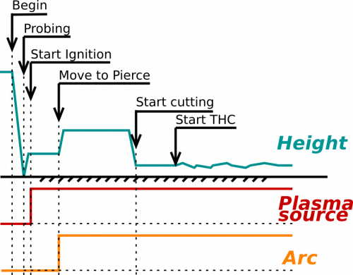
A procedure for start plasma cutting is
- Probe material sheet (move Torch down until the probe sensor pressed)
- Move Torch up to the Ignition Height
- Turn Plasma Power ON, wait until the Arc Transfer (Arc ON) sensor is ready (methods to turn off the Arc Transfer sensor are discussed at the end of this manual)
- Move up to the Pierce Height
- Wait a certain Pierce Time
- Move down to the Cutting Height
- Start Torch Height Control (THC)
- Start XY motion
M71/M03 procedures handle this entire sequence, therefore no additional programming is needed in the G-code. The code provided below is typically used as reference, in case the user wants to compare their current edited code to the default configuration:
- M71.plc
#include vars.h
#include pins.h

#include func_ihc.h
#include func_plasma.h

main()
{
  if (proc==plc_proc_plasma)
  {
    message=PLC_MESSAGE_PLASMA_OK; 	//set OK message and exit
    exit(99);
  };

  timeout_plasma_ready=10000;
  timer=0;

  do_plasma_probe();

  do_move_ignition_height();

  portset(OUTPUT_PLASMA);

  do_wait_plasma();

  do_move_pierce_height();

  do_wait_pierce();

  do_move_cutting_height();

  start_thc();

  start_trigger1();//Arc ON sensor
  //start_trigger2();//Collision Sensor


  proc=plc_proc_plasma; //set OK message and exit
  message=PLC_MESSAGE_PLASMA_OK; 	//set OK message and exit
  exit(99);
};
Functions do_plasma_probe, do_move_ignition_height, do_move_pierce_height, do_move_cutting_height are defined in “func_ihc.h” file (all these are included by default):
- func_ihc.h
// start motion //flags
//  bit 0 - absolute programming
//  bit 1 - machine coordinates
//  bit 7 - delayed start.

//  axes mask
//  bit 0 - X axis
//  bit 1 - Y axis
//  bit 2 - Z axis
//  bit 3 - A axis
//  bit 4 - B axis
//  bit 5 - C axis


do_plasma_probe()
{
  gvarset(7080,ihc_probing_speed);//set speed;
  timer=5;do{timer--;}while(timer>0);


  if (ihc_enabled!=0)
  {
    message=PLCCMD_TRIGGER2_OFF;
    timer=5;do{timer--;}while(timer>0);

    portset(OUTPUT_PROBE);
    timer=200; do{ timer--; }while (timer>0);
    sens=portget(INPUT_IHC);
    if (sens==0)
    {
      g0moveA(0x0,0x4,0-30000);//Z axis,
      timer=200; do{timer--;}while(timer>0);//wait till motion started

      do
      {
        code=gvarget(6060);
        sens=portget(INPUT_IHC);
        if (sens!=0)
        {
          code=1;
          message=PLCCMD_LINE_STOP;//skip line
        };
      }while (code==0);
      do { code=gvarget(6060); }while(code!=0x4d);//wait till motion finished
     };
  };
  portclr(OUTPUT_PROBE);
};


do_move_ignition_height()
{

  speedz=gvarget(7043);
  gvarset(7080,speedz); //Set speed;
  if (ihc_enabled!=0)
  {
     ihc_current_height=ihc_correction_height+ihc_ignition_height;
     if (ihc_current_height>5)
      {
         g0moveA(0x0,0x4,ihc_current_height);//Z axis, ignition_height
         timer=200;do{timer--;}while(timer>0);//wait till motion started
         do { code=gvarget(6060); }while(code!=0x4d);//wait till motion finished
      };
   };
};


do_move_pierce_height()
{
  ihc_current_height=ihc_pierce_height-ihc_ignition_height;

  if (ihc_current_height>5)
  {
    g0moveA(0x0,0x4,ihc_current_height);//Z axis, pierce_height
    timer=200;do{timer--;}while(timer>0);//wait till motion started
    do { code=gvarget(6060); }while(code!=0x4d);//wait till motion finished
  };
};


do_move_cutting_height()
{
  ihc_current_height=ihc_cutting_height-ihc_pierce_height;

  if (ihc_current_height!=0)
  {
    g0moveA(0x0,0x4,ihc_current_height);  //Z axis, cutting_height
    timer=200;do{timer--;}while(timer>0); //wait till motion started
    do { code=gvarget(6060); }while(code!=0x4d); //wait till motion finished
  };
};
How to disable Arc ON input
It is highly recommended to use Arc ON signal from Plasma power source and connect it to ET7 controller Arc ON input to get correct feedback about current plasma state. However Arc ON signal can be disabled in case you don't want to use it. The three potential methods to disable the Arc ON (Arc Transfer signal) are described in this manual.
Setting up IHC and Arc Sensors
The video below shows the steps necessary to set up the IHC/Arc sensors in the X1366P plasma profile:
Necessary steps:
- Connect the Arc and IHC sensors to the control board (can check the port numbers the sensors are connected to in the diagnostics window)
- In Settings > Config > PLC > Hardware PLC > pins.h, locate the INPUT_ARC and INPUT_IHC lines and change the sensor numbers to their correct values if necessary
- pins.h explained:
- Press the Save All, Build All and Send buttons to recompile the PLC procedures on the disk
- After recompiling the PLC, you can check that the sensors are operational in the Plasma tab on the main software screen
- Head into the User Settings window from the main menu and select whether you want the IHC to be ON or OFF. If the IHC is OFF, only the Arc Sensor will need to be triggered for the cutting to proceed, while if the IHC is ON, the IHC Sensor will have to be activated before the cutting process begins.
- The system is now set to recognize the sensors that will be used to begin the cutting process. The IHC sensor MUST be activated before the system will initiate the cut (on the initial lowering of the plasma torch).
The following video illustrates the Initial Height Control process that takes place as the program begins to run:
The sequence will be the following:
- The torch will move down until the IHC Sensor is triggered
- After this, the torch will rise by the defined IHC Ignition Height above the point of contact between the metal and the IHC Sensor and will wait for the arc sensor to be activated
- After the Arc Sensor is activated, the torch goes up to the IHC Pierce Height and stays at that height for the Pierce Time
- After the Pierce Time has passed, the torch will go down to the Cutting Height and begin the THC process.
Drill
Drill setup is done via the program PLCs - as such, the user can accommodate and sort of setup by using capabilities of the built-in PLCs. Such setups are typically unique to the machine, and thus have to be adjusted depending on the machine in questions (plasma/gas, tool change procedure, etc).
Among the possible solutions for drilling setups are the following:
- another Z-axis can be assigned to the drill head
- a spindle can be attached
- the drill head can be used together with plasma (not simultaneously, but within the same g-code program).
- Drill head and plasma are defined as different tools, different tools have offsets, so distance differences are easily taken into account. When switching from drilling to plasma (and vice versa), a tool change procedure is started, in which offsets are taken into account and the necessary tool change actions are performed (for example, putting one head in the parking/working position, switching the Z drive from one drill head to another, etc.).
If a user would like to implement drilling capabilities via myCNC, please contact the Technical Support team which can provide some reference PLC drill programs.
Switching between the Plasma and Gas profiles
This video illustrates the process for switching between plasma/gas without going into the myCNC settings:
- Go to the main software screen
- Click the Main Menu button in the top left corner
- Click the Switch Technology button in the popup menu
- Select the technology you would like to switch to (plasma/gas) and click Confirm
- The profile will reload to the selected cutting technology
- It is then possible to switch back to the original profile from the newly selected gas/plasma profile by following the same steps.
Simulation mode
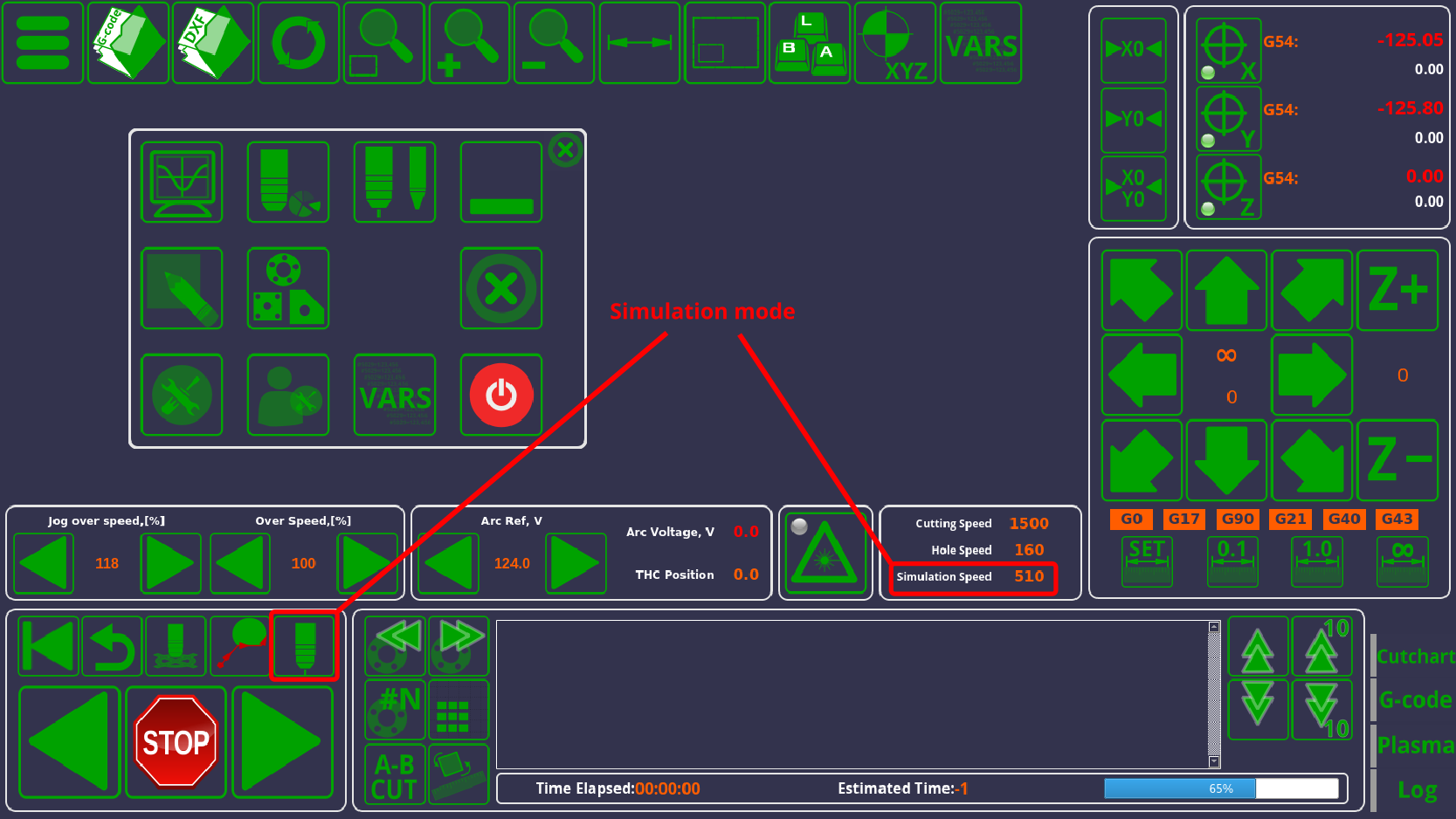
The simulation mode allows the user to run through the program at a separate speed without the cutting commands. This is useful to quickly position the machine to a point that the user requires, or to see how the XYZ movement will play out without the actual cutting commands.
Simulation mode is controlled using the following button and speed selection option:
AB Cut (manual cut)
A manual cut allows the user to utilize two points (A and B) to cut a straight line from one point to the other.
A video on the AB Cut function is available:
Controller connection examples
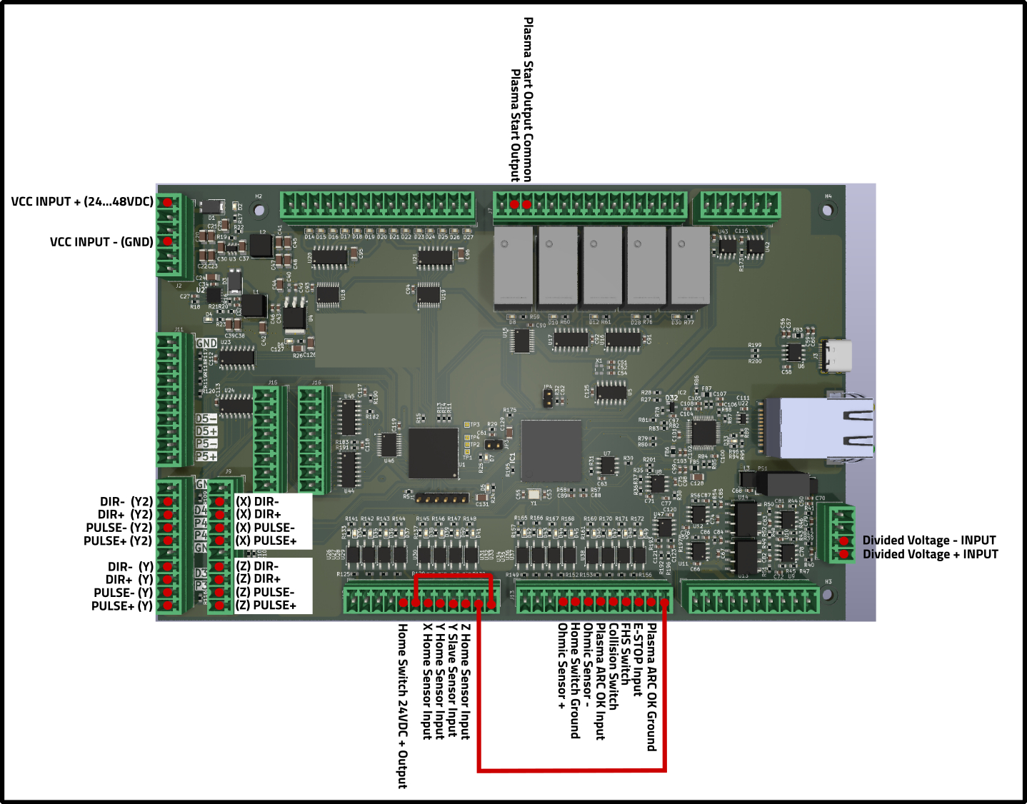
Below is an example of some of the ports that can be utilized on an ET7A (ET9) board when using a typical plasma cutting table:
The diagram demonstrates the following connections:
- Power (VCC inputs)
- 4x pulse-dir motors. In this example, the table has a motor on the X, a motor on the Z, and two motors on the Y axis (Y/S side of the gantry).
- Voltage input from the plasma unit for THC
- Inputs for homing sensors (X, Y, S, and Z)
- E-Stop, FHS, Ohmic sensor inputs
- Plasma Start relay output
Note that the diagram above is only an example. The specific outputs and combinations of sensors can be changed depending on the user needs.
Hypertherm Powermax Connections
ET7
An example of connecting the ET7 control board to the Hypertherm Powermax 45 XP power source is available below:
| Socket Number | Hypertherm wire colour | Signal Description | myCNC Pin |
|---|---|---|---|
| 3 | Black | Start plasma | OUT15(A) |
| 4 | Red | Start plasma | OUT15(B) |
| 12 | White | Transfer (start machine motion) | VCC1 |
| 14 | Green | Transfer (start machine motion) | IN3 |
| 5 | Black (-) | Voltage divider | ADC0(-) |
| 6 | Red (+) | Voltage divider | ADC0(+) |
In this example, the OUTPUT_PLASMA is defined as OUT15 (relay 4), while INPUT_ARC is defined as IN3. The system uses ADC0 which is designed for the 1:50 voltage divider from the power source.
ET10
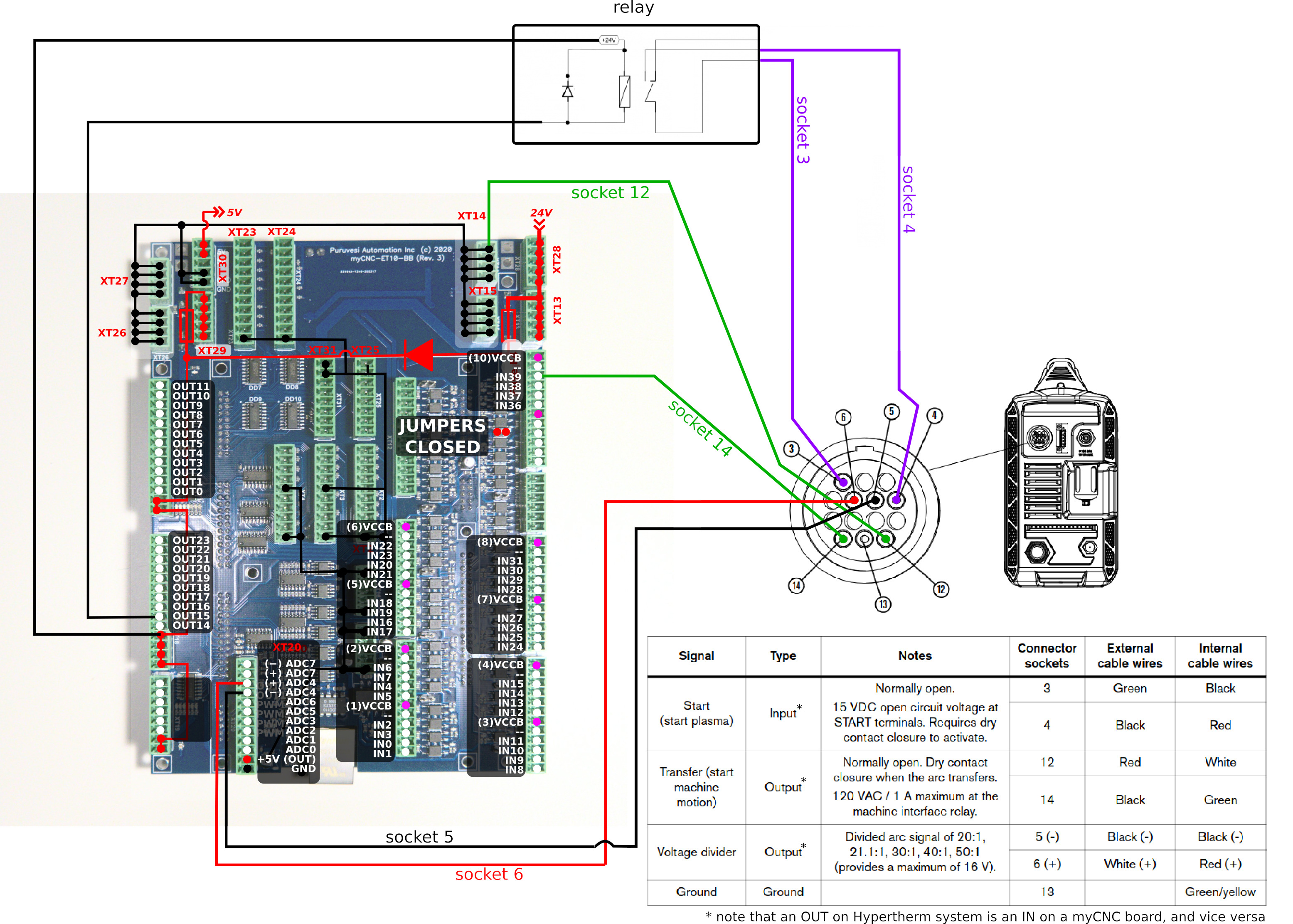
An example of connecting the ET7 control board to the Hypertherm Powermax 45 XP power source is available below:
Unlike the ET7 which features relay ports on the control board itself, for the ET10 the system requires an additional relay connected to an output port (not provided in the myCNC kits). See the diagram above for connection information.
Note that the IN and OUT ports are selected arbitrarily, i.e. you can utilize different port numbers depending on your system setup. For instance, IN39 is used in the diagram above as the Transfer (Start Machine Motion) input, however the user can select any other input, provided it is wired correctly (proper jumpers closed, etc).
To ensure that the system functions with the port numbers that the Hypertherm power source has been connected to, make sure to check the following:
- pins.h file. The pins.h file was already described in the above manual, in the Inputs connection > Arc Transfer, IHC sensors section. Here, make sure to use the actual INPUT_ARC and OUTPUT_PLASMA that are connected to the board (if those differ from the profile defaults).
- ADC channel number. The system requires a correct ADC channel number to monitor arc voltage for THC feedback. See the Arc Voltage section in the manual above for more information. In this example, the system uses ADC4 which is designed for the 1:50 voltage divider from the power source.
- Trigger settings (to stop the program when Arc signal fails during cutting). The manual on triggers (and specifically on the arc signal trigger) is available here: Triggers
- for the trigger, use the correct Transfer input and the Falling Edge option


