Table of Contents
Main Advantages of myCNC Software
The primary purpose of a CNC system is to move the machine and to control the peripheral devices according to the control program written in G-code. Practically all CNC systems are able to cope with this main task, and in this regard, all CNC machines are roughly on the same level.
When comparing CNC systems, one must therefore talk about various additional opportunities that are present within the CNC control system. Although these additional features are often optional, their presence allows for: - increased productivity, - improved accuracy and quality of cutting, - reduced machine downtime, - improved usability and - reduced training requirements for the personnel working on the machine.
This article goes over a number of such advantages and opportunities that are present in myCNC software compared to the other major CNC control systems.
Stopping and resuming the program
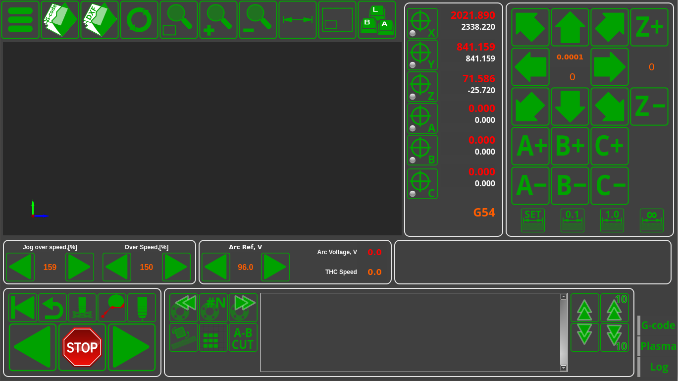
At any point, the operator can stop the running program by pressing the Stop button, and then resume the program by pressing the Run button. Stopping and then running the program again is possible even during the process of linear or circular interpolation. When resuming the program, the CNC system will automatically detect and, if necessary, add an ignition cycle.
Furthermore, after stopping you can manually move the cutter to a position that is convenient for the operator (for example, to inspect the plasma torch and replace the nozzle or an electrode), and then return the cutter to its original stopping point by pressing the “Return” button.
Despite its simplicity, such a function is absent in some major CNC systems that are designed primarily with milling in mind (such as Mach3 or LinuxCNC).
Stopping the program using the arc sensor
This function is similar to the one described above, however, the program is stopped automatically due to a break in the plasma torch arc. The program can be resumed by pressing the Run button after eliminating the source of the break (by cleaning the plasma torch, replacing the nozzle, etc).
Simulation mode
By pressing a button on the remote control or on the screen of the control system, the system can be set to a simulation (jog toolpath) mode. This will ignore the start commands for cutting, initial positioning and firing cycles. When launching the control program, the machine will only perform idle movements within the program (movements at the working cutting speed or accelerated movements at the idle stages speed are also possible).
Running the program backwards and forwards
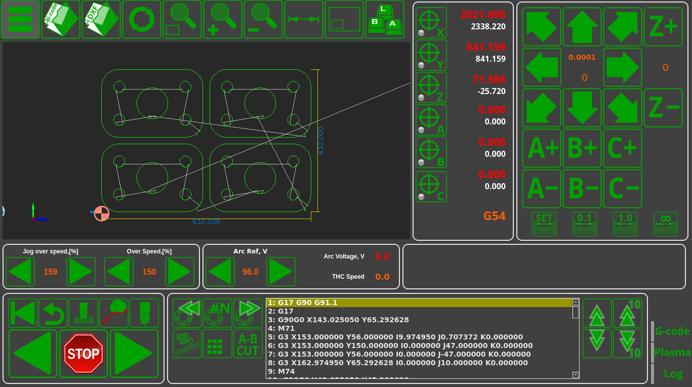
In simulation mode, one can move within the program both forwards and backwards. This is extremely useful in case the operator needs to cut out a part from the few remaining bits of material, and an idle run is necessary to check that the part can fit in the space that remains before the actual cutting starts.
Fast forwarding for cutting commands
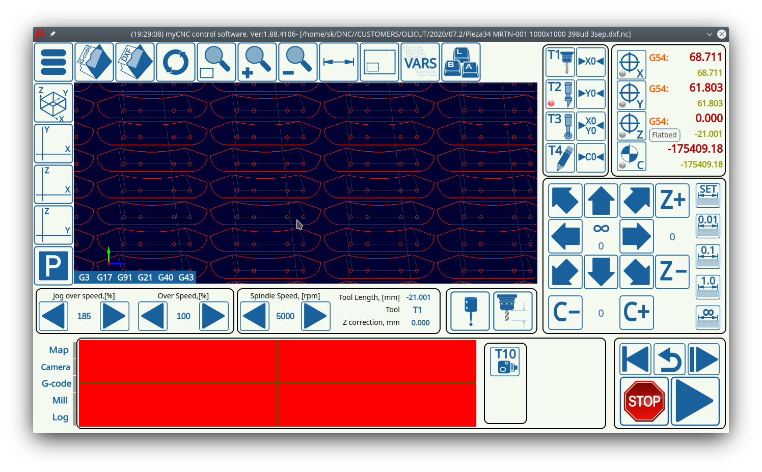
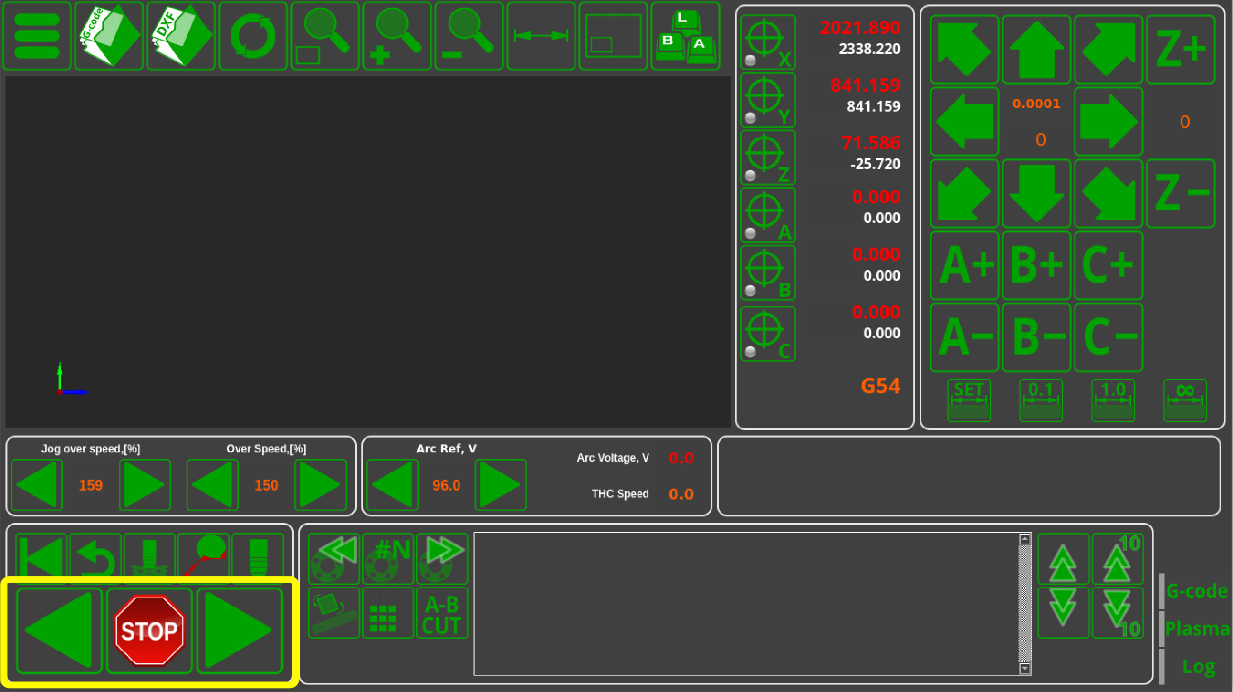
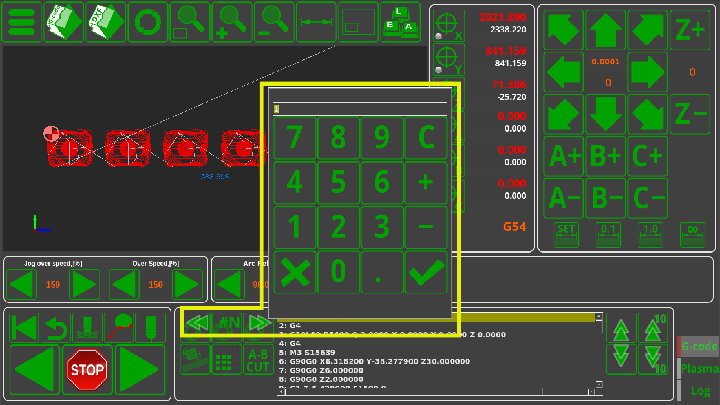
By pressing the remote control buttons, one can run the current command indicator through the cutting commands, in order to have a clear visual way of selecting the necessary part from the cutting map. It is possible to sequentially move through the cutting commands or select the desired cutting command by typing in its number. The function is very useful if you need to, for example, re-cut only Part 27 out of 50.
In comparison with the “search by frame number” method employed by traditional CNC systems, this implementation performs significantly better in terms of time spent and ease of operation.
Hole Cutting
A 2D (or a 2.5D) file such as the one shown above contains both the outer and the inner contours of the part being cut. In certain applications (such as plasma cutting, tangential knife cutting) it is preferable to have a separate (often lower) speed for the holes that are located inside the main contour. However, a number of CAM programs do not accommodate for this need if they do not have an implementation for two separate speeds.
To solve this issue, myCNC features an Arcs Slow Speed Control settings (Settings > Motion) which allows the user to quickly set up hole cutting speed based on the arc diameter of the hole in question:
Detail Multiplication
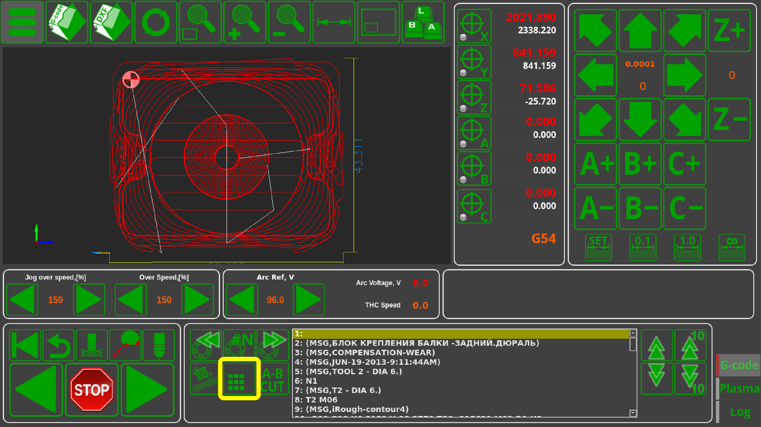
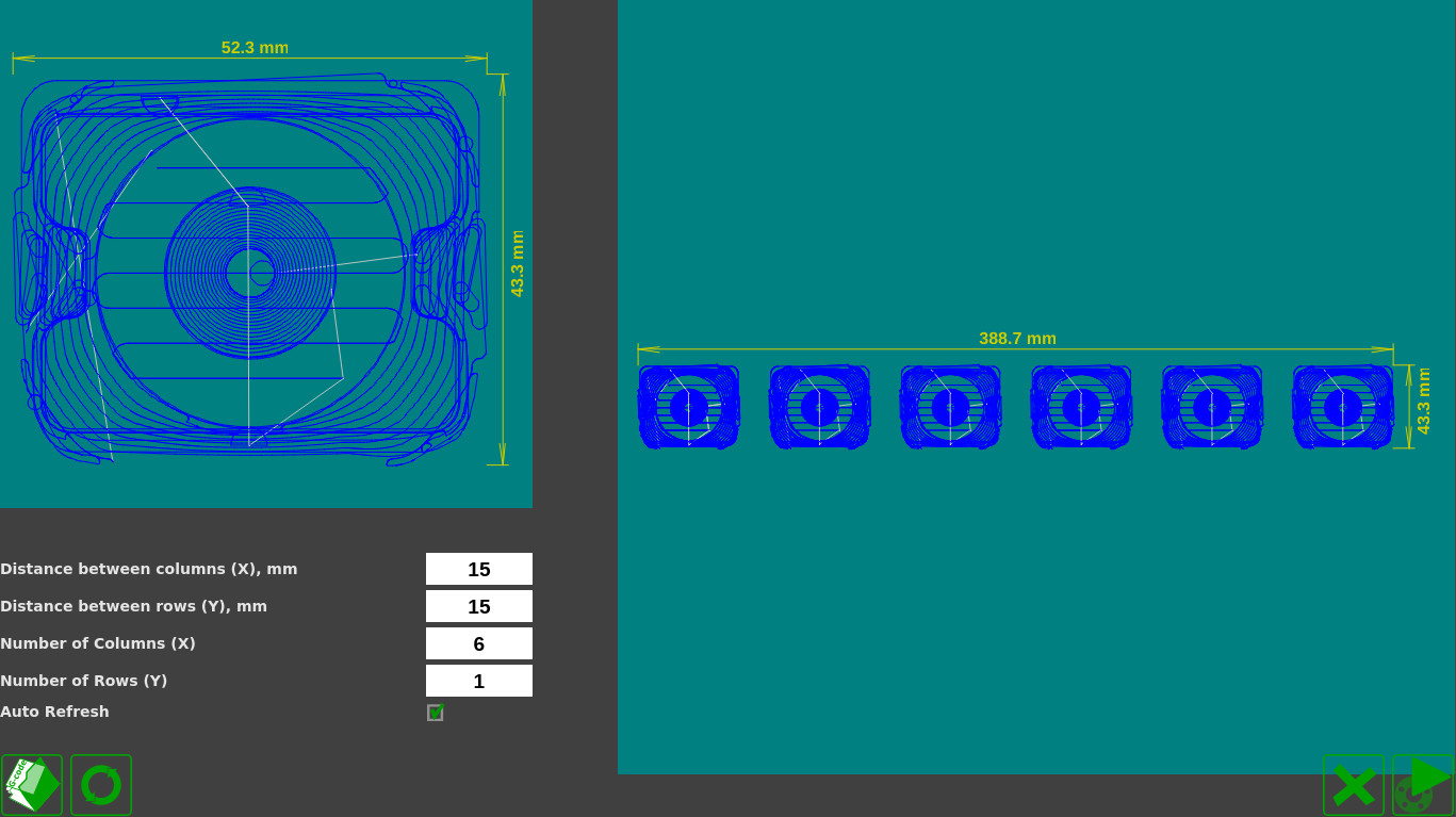
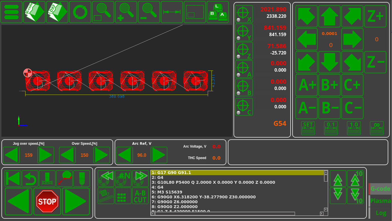
In a few easy clicks, multiples of the part can be set up, by setting a desired number of parts and the distances between them. For further information, please consult the row and column nesting manual.
Rotating the program file by a specific angle
The control program can be rotated by an angle that is desirable for the operator. This can be done by inputting the value for the rotation angle manually, or by allowing the system to determine this value using two specified points. Mirror rotation around the OX, OY and XY (x=y) axes is also possible.
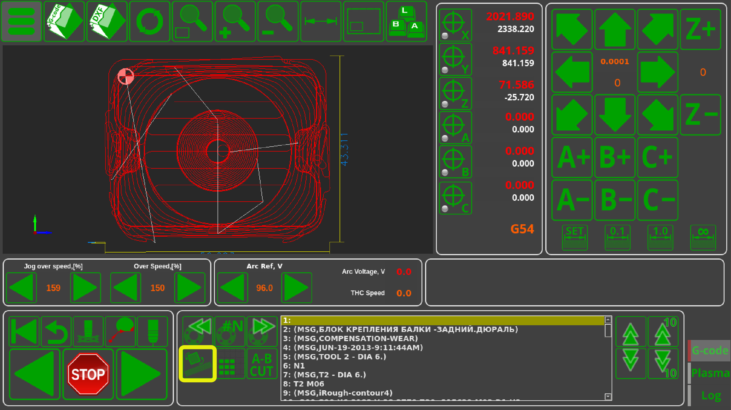
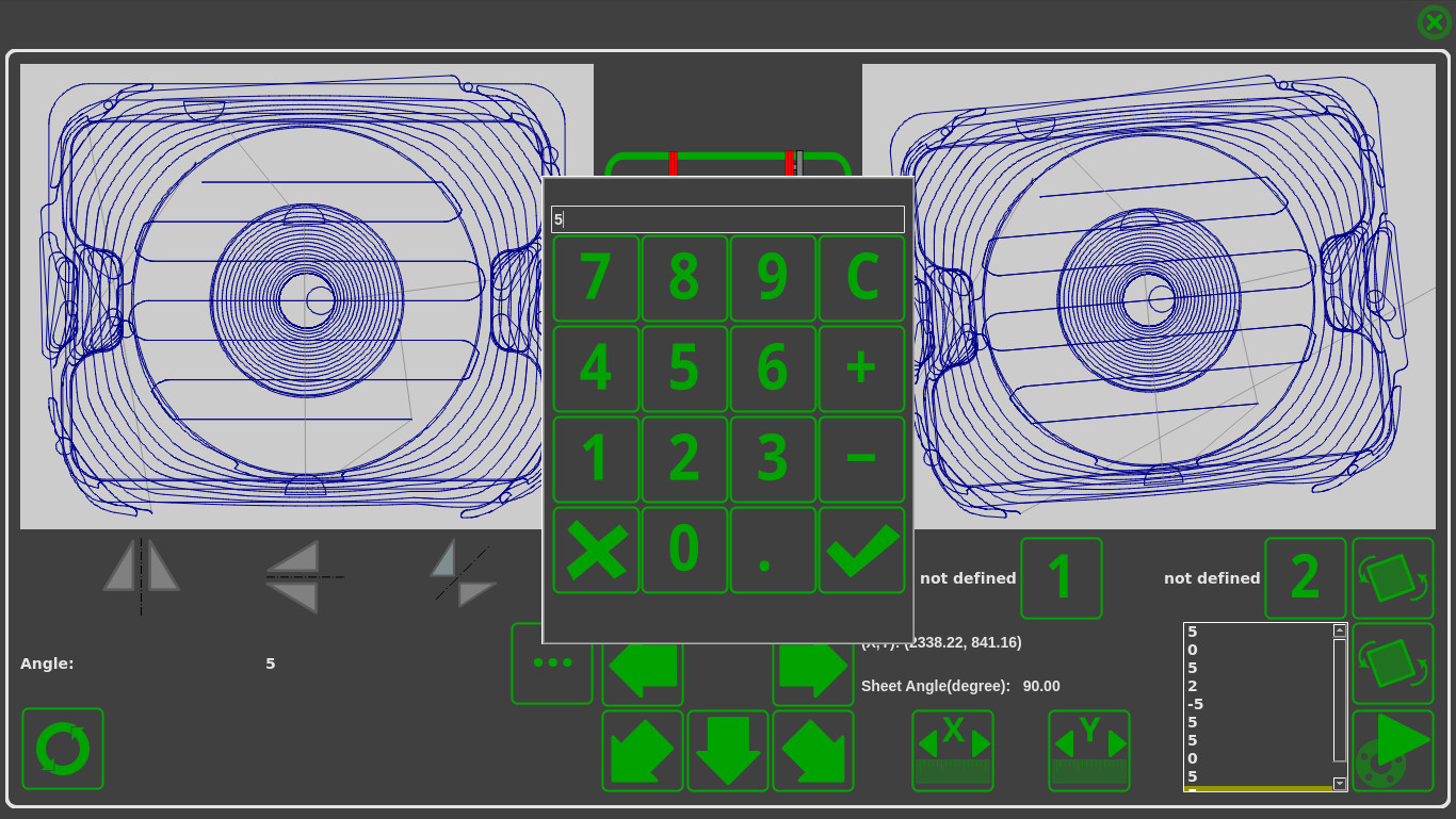
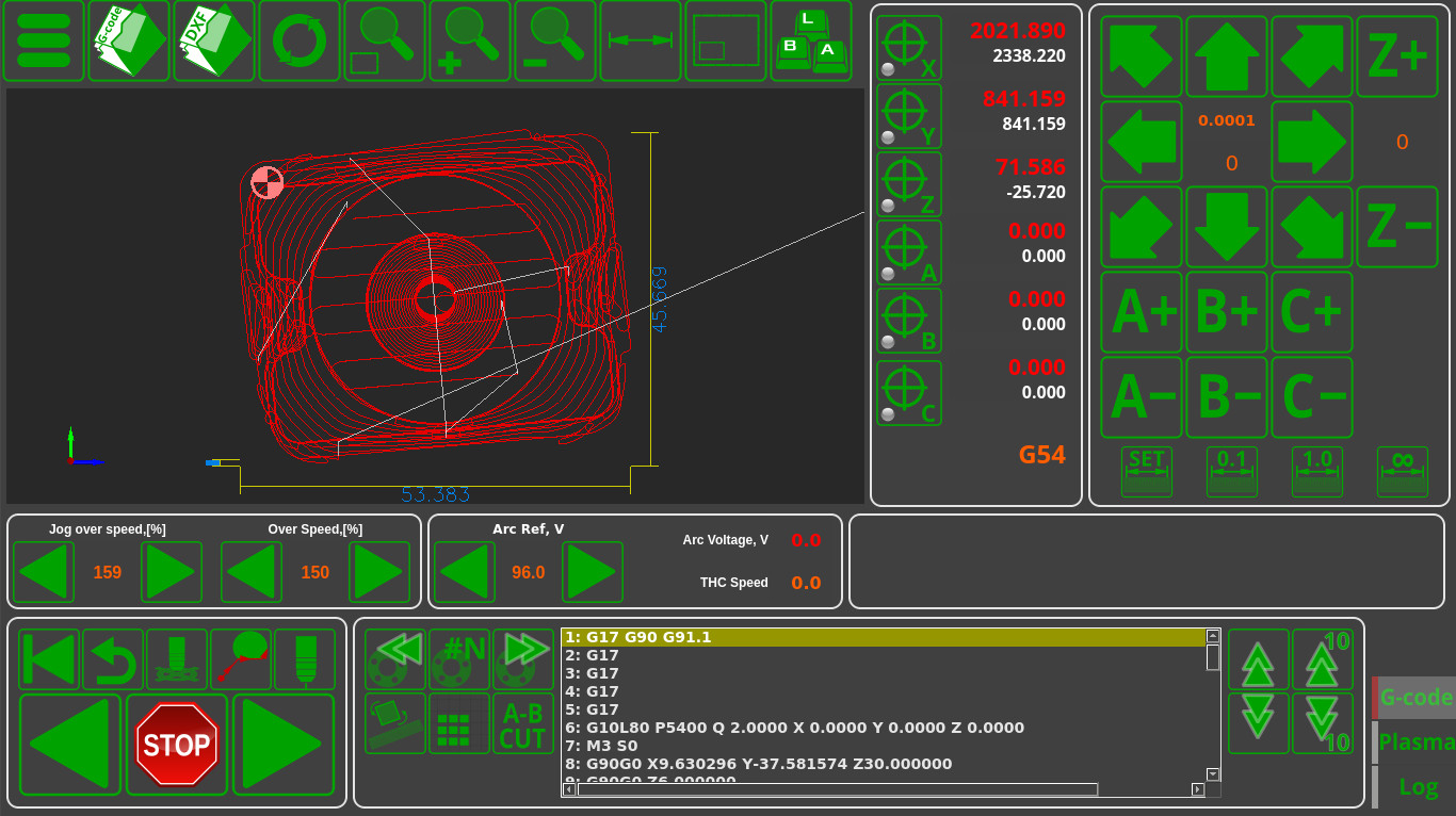
The rotation function is highly useful in situations like:
- A heavy sheet that has been put down slightly asymmetrically, with the cutting map having to be adjusted to take this sheet rotation into account
- Using the last remaining bits of material that require the part to be rotated or mirrored in order to fit it in
Read more about this feature here.
Cutting from the edge of the sheet
In case the cutting is done on a thick sheet, it can be hard to perform the initial cut in order to punch through the material for the first time. In this case, the edge cutting function can be used, since the breakthrough process is a lot less demanding if performed on the edge of the sheet. In this mode, a spot for the cut will be selected, the part itself is selected through scrolling to the necessary cutting command (as shown above), after which the operator can move the machine from the cutting position to the closest point at the edge of the material sheet and turn on the edge cutting mode.
This will automatically start the initial contact and ignition procedure, after which the machine will move directly to its actual cutting position upon reaching which it will continue to execute the cutting program.
Parts Library
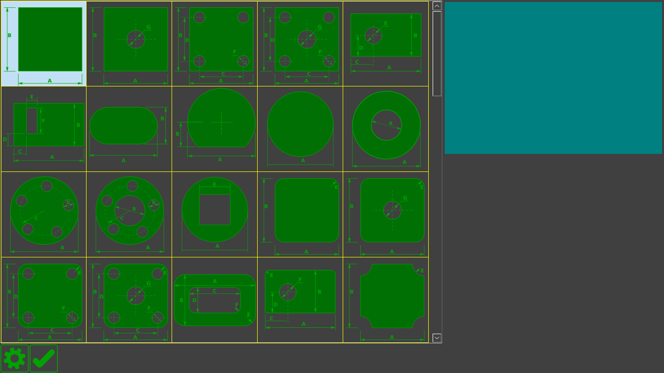
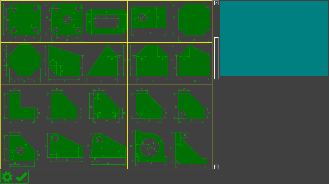
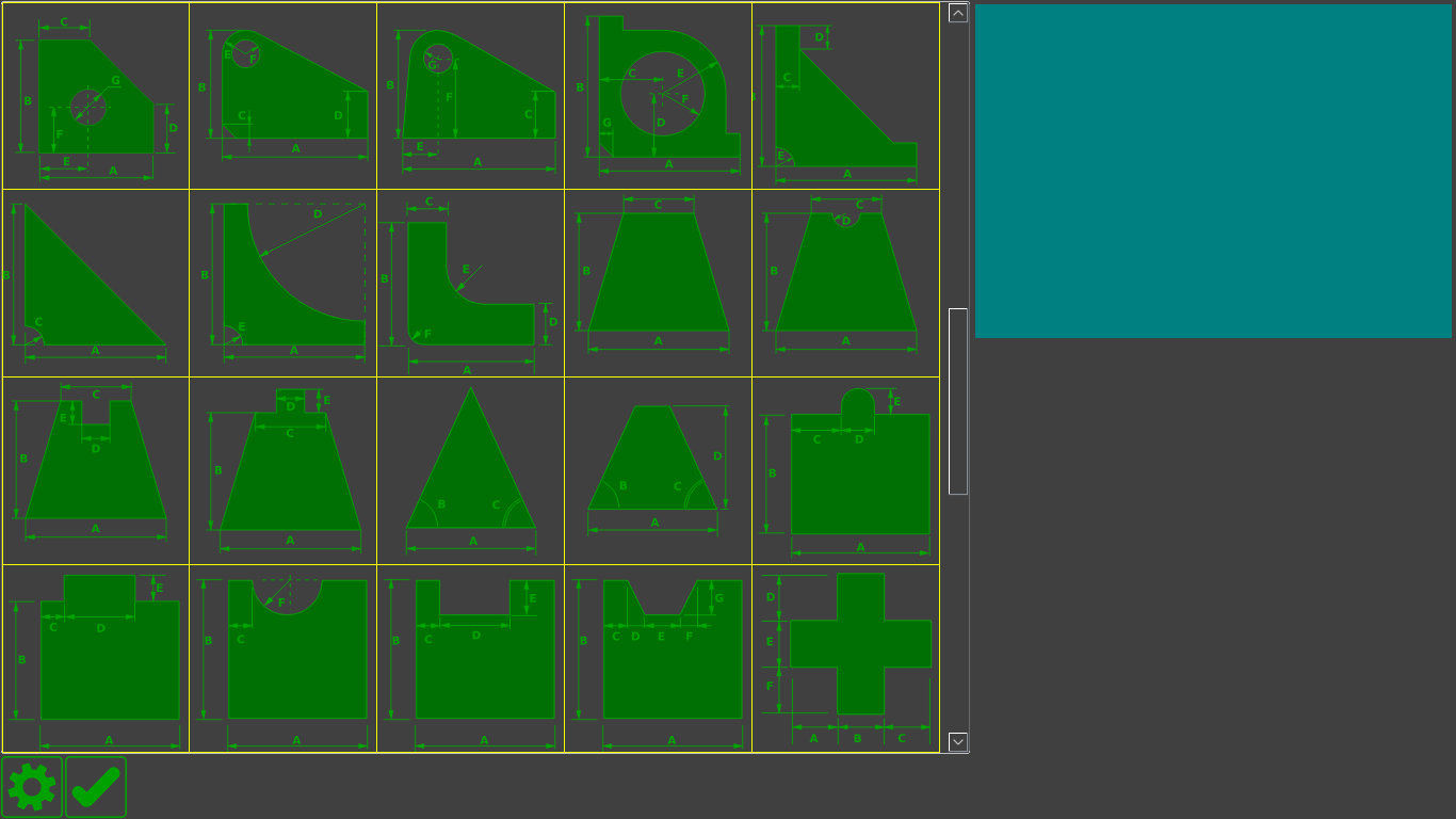
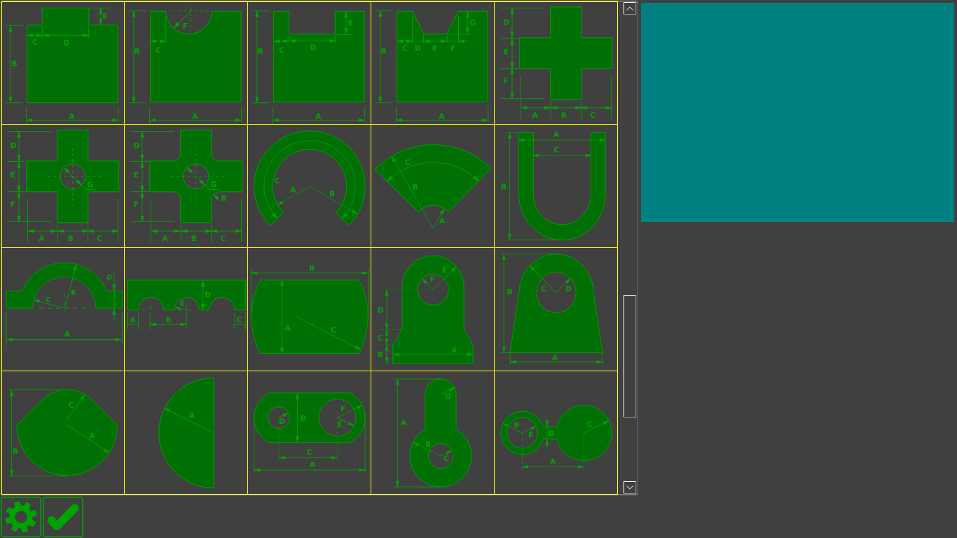
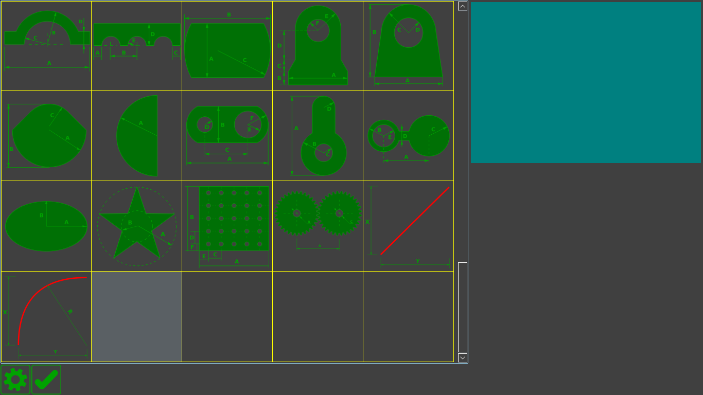
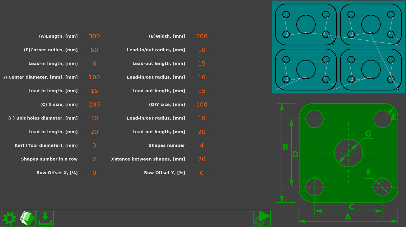
myCNC includes a library of more than 70 default parts which can be altered according to the user's specifications. The parameters that can be changed are:
- the size of the part
- the cutting method (plasma, oxy-fuel, etc, milling, etc)
- the number of parts per row and the overall number of parts
- distances between parts
- corrections for the tool cutting width
- type and size of cut
- part shifting
Using the software functions provided, the operator can create a simple cutting control program straight from the CNC machine in a couple of minutes, without having to consult the engineering department or having to use expensive CAM software. In certain cases, the user can forego using CAM software entirely, by simply using the bundled-in functions of the myCNC parts library.
Importing and converting DXF into G-code
myCNC software allows to import simple CAD files in the DXF format and is able to convert them to control programs in G-code. As well as importing the movement trajectory, one can also add the cutting specifications and the reverse movements for the machine by entering the length and the type of the cut (straight or on a curve).
The results of the system working with such an imported DXF file, library parts, or part multiplication are saved as G-code files. Therefore, the myCNC software can be used with third-party CNC control systems to prepare the necessary G-code commands.
Cut Charts
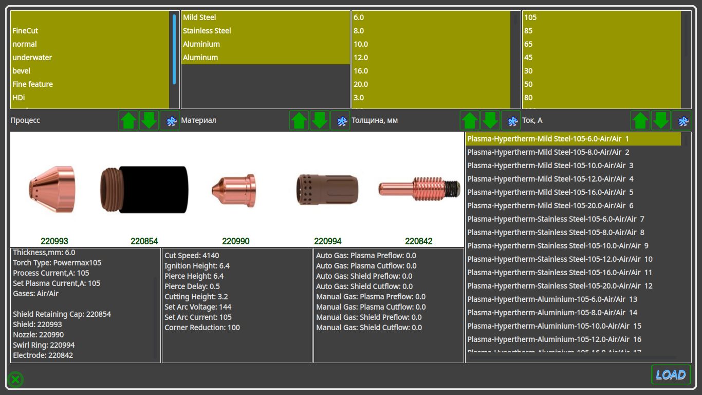
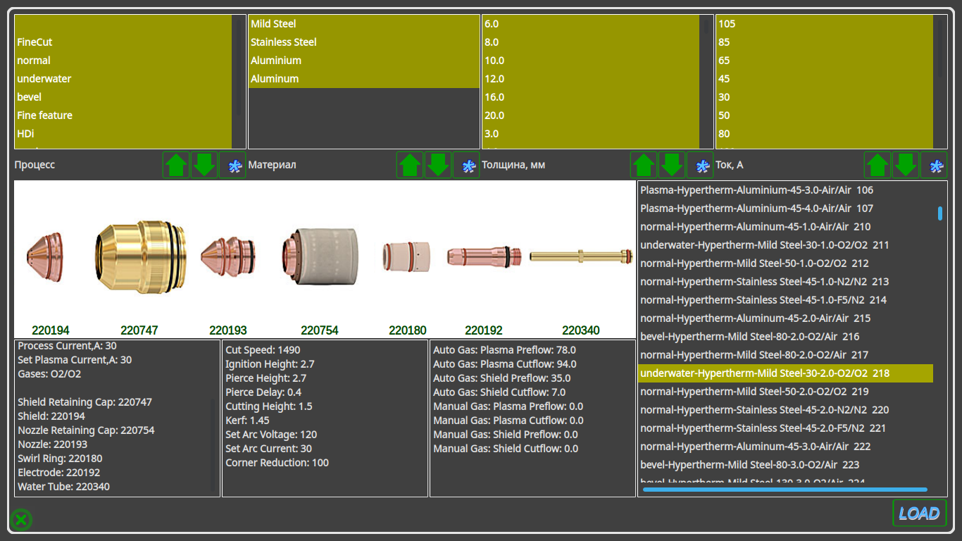
myCNC software makes it possible to create cut charts for different types of plasma cutting sources. The list of parameters that the operator indicates when loading a module from a table can be configured. Usually the following parameters are considered:
- material (regular steel, stainless steel, aluminum, titanium, etc)
- thickness
- cutting current
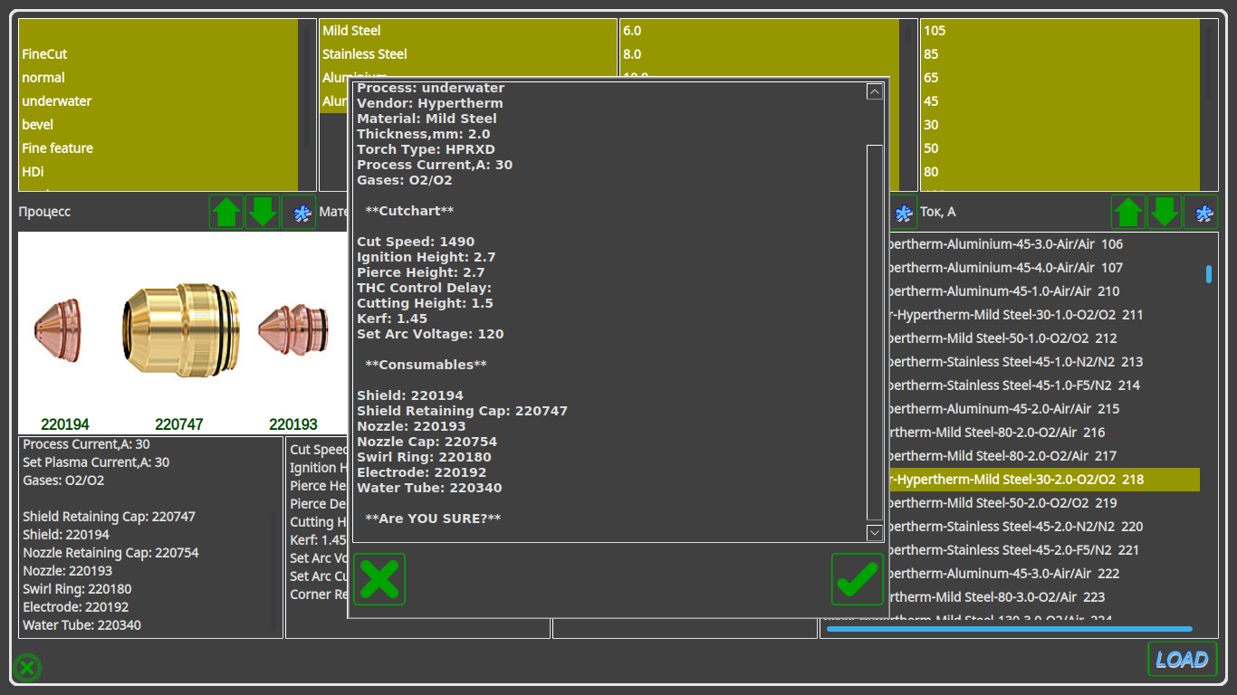
When loading the control system, the following parameters will be loaded from the cut charts (provided they have been inputted)
- Cutting speed
- Ignition height
- Punching height
- Punching time
- Cutting height (arc reference voltage for THC)
- Cutting current
- Magnitude of current decrease at the trajectory corners
- Cut width adjustment (kerf)
- Crawling speed (during punching through)
- Driving time at creeping speed (when punching)
- The delay time to enable tracking after punching
- Gas parameters for manual and automatic Hypertherm console (type of cutting and shielding gases, MixGas1, MixGas2 gas mix values, plasma torch cutting and shielding channel pressure values during Preflow and Cut)
- Consumable components of the plasma torch as auxiliary information for the operator of the machine (types of electrodes, nozzle, protective nozzle, protective cap, swirl and water tube)
Torch Height Control
Unlike many CNC systems, myCNC has full integration of the THC (torch height control) system. This brings along the following benefits:
- Cutting height (THC reference voltage) is set in the CNC system itself (not on an external THC, as in many other systems). In addition, the optimal value for the cutting height can be loaded from the Cut Chart when selecting the material thickness.
- The system implements several algorithms to prevent the plasma torch from diving - a THC start delay, THC preemptive shutdown, and THC momentary shutdown when cutting speed drops below a predetermined value, as well as during abrupt voltage surges.
NOTE:

Arc voltage is not stable for the first few tens or hundreds of milliseconds
after the material has been punched through.

At the end of the cutting process, the plasma torch passes over an already cut out trajectory,
where the arc length and the arc voltage increase.

The arc also lengthens and its voltage increases at the corners of its path as the
cutting speeds lower and and more material is burned though.

When the arc passes through the cut, the arc voltage can increase
up to a few dozen volts.

All of these factors can lead to short-term diving when running THC,
leading to the plasma torch nearly touching the material

Timely reactions to such situations and short-term blocking of
torch height control in such scenarios is an effective method of diving prevention.
- In addition to the work on the pre-set arc voltage (loaded from the table), the THC myCNC system is able to measure the real arc voltage after punching and is to maintain this voltage during the cutting process. This tracking method is becoming increasingly popular, as it allows you to get away from the effect of “floating” the arc voltage during the life cycle of the plasma torch consumables. The arc voltage when using new nozzle electrodes will differ from the arc voltage when using nozzle electrodes that have completed several hundred ignitions. In this case, when the arc voltage is preset (loaded from the table), the system will control the constant voltage level by changing the height of the plasma torch. Turning on the voltage tracking mode will ensure that the plasma torch height remains constant.

