Table of Contents
Importing DXF files into myCNC
NOTE: The myCNC DXF import is provided AS IS, and may not be suitable as a full-fledged CAM software package replacement. The DXF import functionality performs best on simple contours, and is limited in scope for certain applications (plasma, etc). Please consult the myCNC team for more information on DXF import functionality.
The following manual is designed to give the reader a quick introduction on importing DXF files into myCNC software to convert to G-Code. Note that the DXF import window allows the user to combine different technologies, provided that their tool paths have been drawn in different layers (DXF files) or in different pens/colours (HPGL files). That will allow to assign a particular technology to each such layer/pen (for example, using a spindle or a marker alongside a tangential knife). The myCNC software will automatically add all the necessary tool change and tool lift macros when generating the G-code file from the imported drawing.
A quick overview of the DXF import functions is available here:
An introduction to combining different technologies for different layers of the original drawing can also be seen in the camera vision video (relevant information begins at 5:20). Note that while the examples shown are specifically for the tangential knife and camera tools, the principle remains the same for all the other available options (half-knife, creasing wheel, spindle, plasma, marker, etc):
DXF Import Main Screen
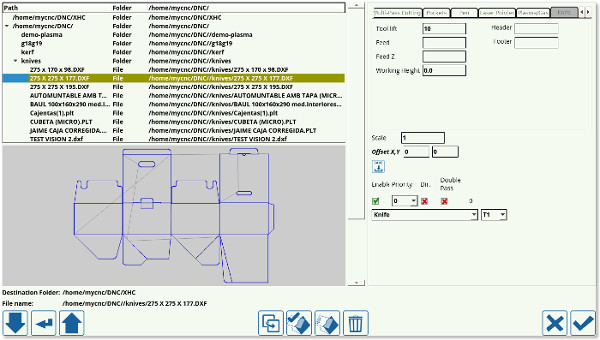
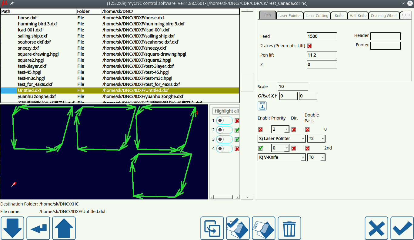
Upon pressing the Open DXF file and navigating to the particular file you would like to open, the following window is shown:
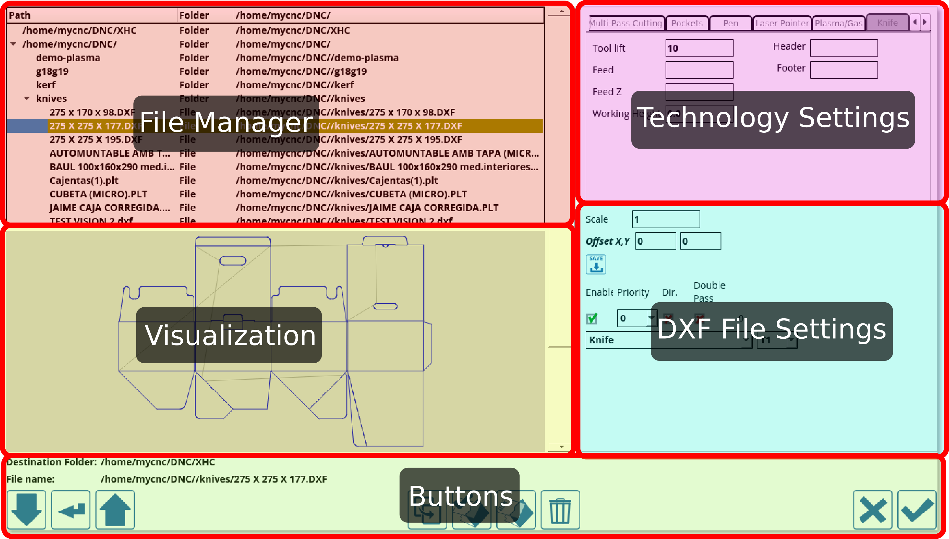
This window can be split into the following areas:
File Manager
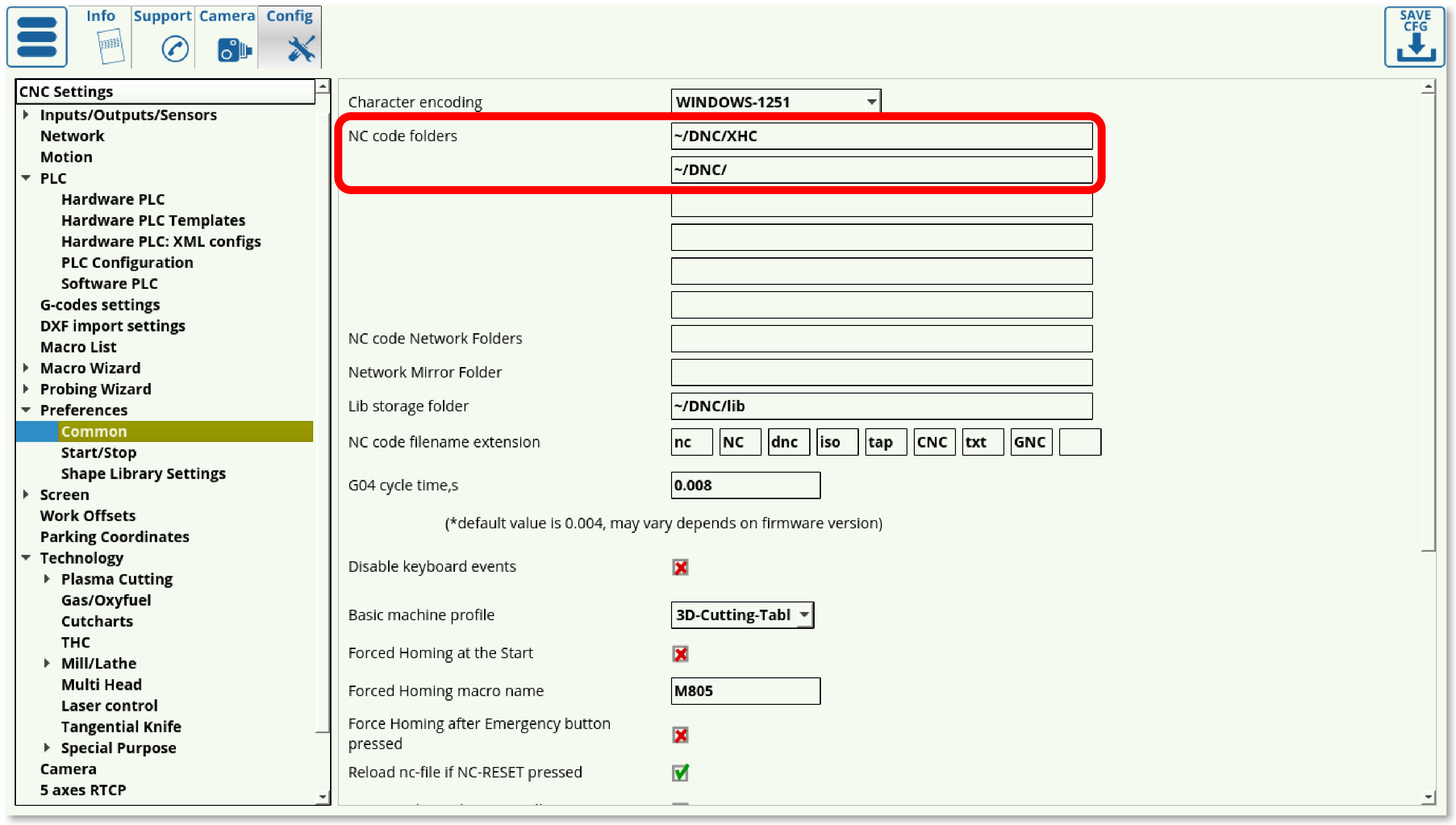
The file manager allows the user to pick the particular DXF file they would like to open. Note that the folders available to the user through myCNC software's DXF import feature are listed in Settings > Config > Preferences > Common. Only the folders listed there can be accessed during the importing process.
Technology Settings
As can be seen in the Technology Settings section, the list of available technologies is as follows:
- Engraving
- Multipass cutting
- Pockets
- Pen
- Laser Pointer
- Plasma/Gas
- Knife
- Half-knife
- Creasing wheel
- Knife-45
- Marking
- S-knife
- V-knife
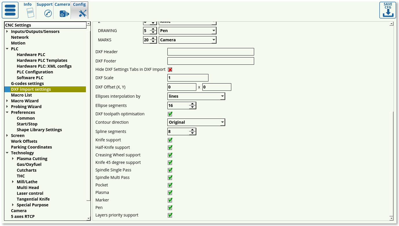
The settings for these technologies can also be accessed through Settings > Config > DXF import settings. Depending on the user's needs, unnecessary technologies can be disabled to reduce screen clutter.
Below are the descriptions of the available settings for each of the technologies listed in the Technology Settings:
Engraving
- Tool lift: Specifies the height to which the tool is lifted as it travels between the parts
- Z: Working height (usually a small negative value for engraving)
- Feed: Specifies the speed with which the machine is moving in the XY plane
- Feed Z: Specifies the speed with which the machine is moving in the Z axis
Multipass cutting
- Tool lift: Specifies the height to which the tool is lifted as it travels between the parts
- Material thickness: Specifies the thickness of the material in mm
- Cut depth: Specifies each consecutive cut depth
- Feed: Specifies the speed with which the machine is moving in the Z axis
Pockets
- Tool lift: Specifies the height to which the tool is lifted as it travels between the parts
- Pocket bottom: Specifies the total depth of the pocket
- Cut depth: Specifies the depth of each consecutive cut
- Tool diameter: Specifies the diameter of the tool
- Finishing: Specifies the depth of the last cut layer (allows to add a small finishing cut for higher precision)
- Feed: Specifies the speed with which the machine is moving in the XY plane
Pen
- Pen lift: Specifies the height to which the pen is lifted as it travels between the parts
- Z: Specifies the working height
- Feed: Specifies the speed with which the machine is moving in the XY plane
Laser Pointer
- Laser pointer lift: Specifies the height to which the laser pointer is lifted as it travels between the parts
- Feed: Specifies the speed with which the machine is moving in the XY plane
Plasma/Gas
NOTE: The DXF import functionality performs best on simple contours, and is limited in scope for plasma and gas cutting applications.
- Mode: Select between Line, Arc, and Tangent
- Line length: Specifies the line length
- Line angle: Specifies the angle of the line
- Arc Radius: Specifies the radius of the arc
- Lead In from the middle: Specifies whether you want to lead into the cut from the middle of the cutting area
- Feed: Specifies the speed with which the machine is moving in the XY plane
Knife
- Tool lift: Specifies the height by which the knife will be lifted as it travels between parts.
- Feed: Specifies the speed with which the knife moves in the XY plane
- Feed Z: Specifies the speed with which the knife moves in the Z plane (during lift)
- Working height: Sets the working height (usually left at 0)
- Header: Inserts macros into the beginning of the generated G-code
- Footer: Inserts macros at the end of the generated G-code
Half-knife
- Tool lift: Specifies the height by which the half-knife will be lifted as it travels between parts.
- Feed: Specifies the speed with which the knife moves in the XY plane
- Feed Z: Specifies the speed with which the knife moves in the Z plane (during lift)
- Working height: Sets the working height (usually left at 0)
- Header: Inserts macros into the beginning of the generated G-code
- Footer: Inserts macros at the end of the generated G-code
Creasing wheel
- Tool lift: Specifies the height by which the creasing wheel will be lifted as it travels between parts.
- Feed: Specifies the speed with which the knife moves in the XY plane
- Feed Z: Specifies the speed with which the knife moves in the Z plane (lift/descend)
- Working height: Sets the working height (usually left at 0)
- Header: Inserts macros into the beginning of the generated G-code
- Footer: Inserts macros at the end of the generated G-code
V-knife
Knife that's held at an angle (often a 45-degree knife). Typically used for simple shaped (lines, rectangles, etc). Double Pass option is currently (as of September 2022) only used on the V-knife, allowing to go back and forth cutting the material from both sides.
A typical task that is solved by using a V-knife is to create boxes for ventilation - strips are cut out and rolled into a square pipe.
- Tool lift: Specifies the height by which the 45-degree knife will be lifted as it travels between parts
- Material thickness: Specifies the material thickness in mm
- Knife 45 degree width compensation: Specifies the necessary width compensation
- Knife XX angle: The angle of the inclined knife can be set to other than 45 (such as 22.5 degrees)
- Feed: Specifies the speed with which the 45-degree knife moves in the XY plane
- Feed Z: Specifies the speed with which the 45-degree knife moves in the Z plane (lift/descend)
- Working height: Usually left at 0.
V-knife also has the direction of cut functionality for its contours:
In the examples above, two contours are selected to be cut clockwise, while two are selected as counterclockwise.
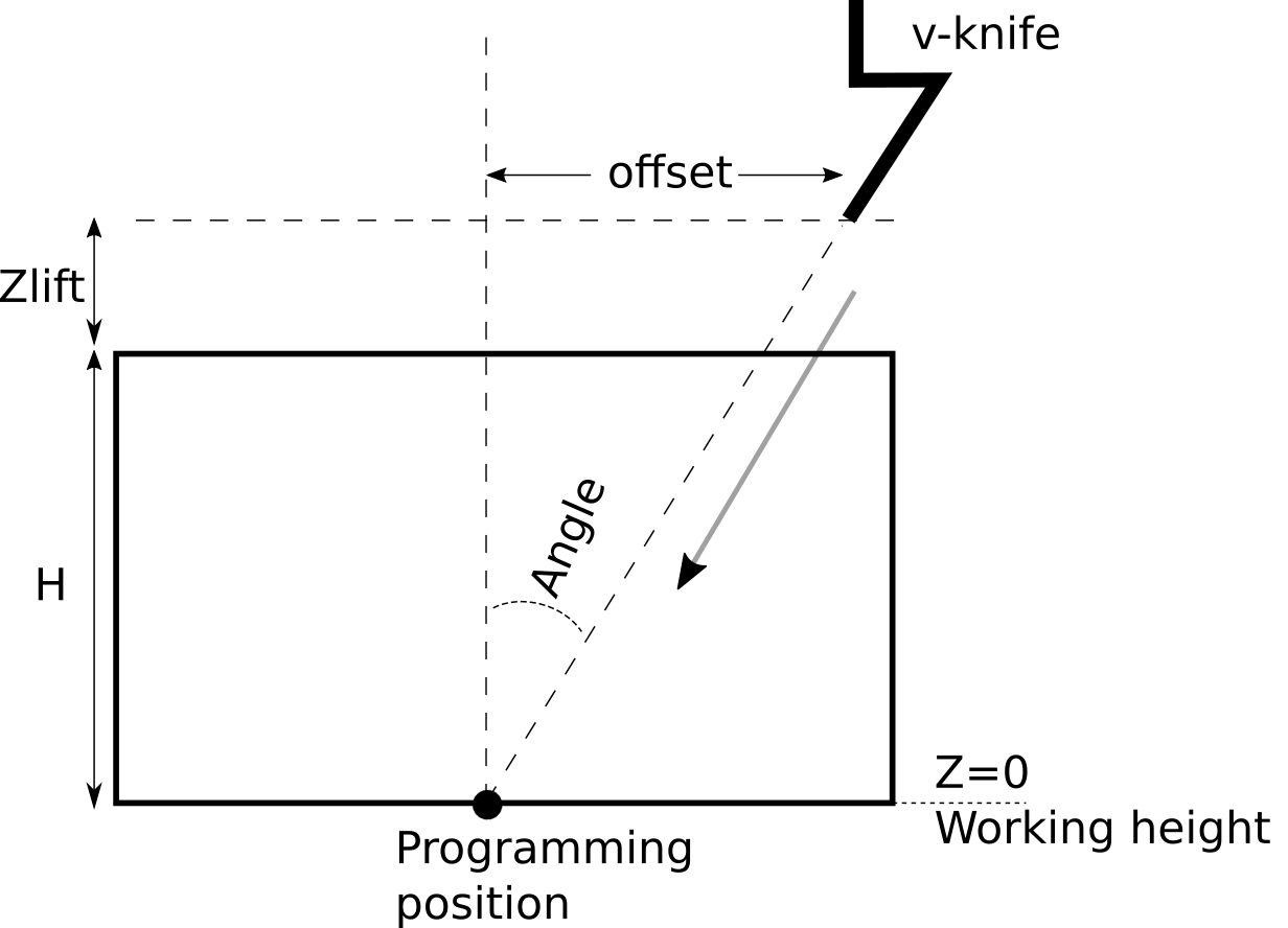
A diagram illustrating a typical v-knife setup:
In the diagram above, the working height is the cutting height. The entry is made at H, the material thickness, plus the lift height.
NOTE: As V-cut and V-knife functionality is primarily designed to cut materials such as thick foams (of a set given thickness), no additional options are provided for applications such as chamfering.
For each straight cutting section, a displacement perpendicular to the movement is taken depending on the thickness of the material and the lift value, an incision is made so that the knife will arrive to a given XY coordinate when it reaches the working height.
At the end of the cutting line, the knife is removed from the material and is moved ont the next line (taking correction into account). For this reason, the current implementation does not works on circles/arcs - when attempting to make a curve, the knife will be inserted and removed at joint points, resulting in an uneven/chopped edge. Therefore, V-knife functionality is currently recommended for straight line cutting only.
S-knife

Similar to regular knife (“straight-knife”), however the rotation is limited to +-180 degrees.
Knife-L180

Similar to S-knife, custom client modification.
DXF File settings
The DXF file settings allow the user to specify the particular tools and tool numbers used for each layer of the DXF file, as well as edit the following options:
- Scale: of the DXF file
- Offset XY for the offset values
- Enable toggle to quickly turn the tool ON and OFF
- Priority
- Direction toggle
- Double-pass toggle
Layers and colours for tool paths
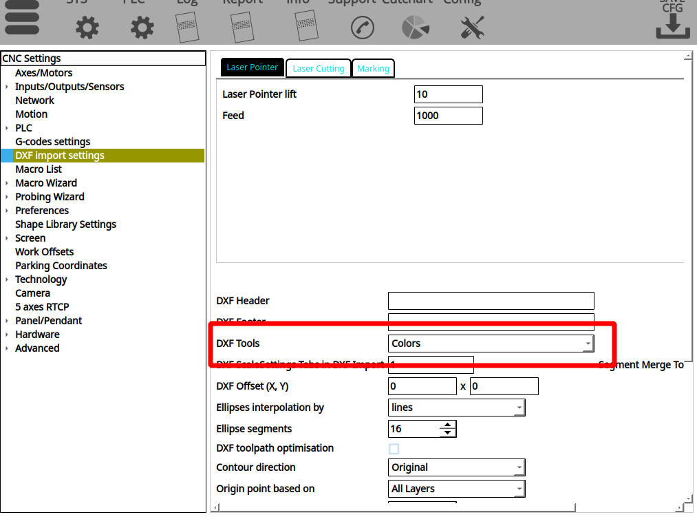
myCNC (as of version 1.88.5609) allows the users to assign different tools within the generated files to different colours (as opposed to the standard layers). In order to enable this option, head into Settings > Config > DXF Import Settings, and enable the Colors option for DXF Tools:
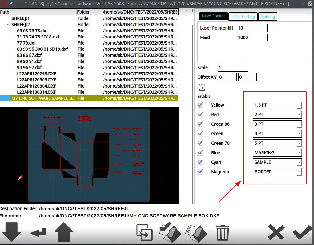
This will make the DXF files with different colours per specific contours to be recognized as distinct tool paths, which you can then assign to the necessary tools at the DXF Import screen:
(NOTE: The above screenshot also features the laser cutting DXF import mode: Laser Cutting)
DXF toolpath optimization
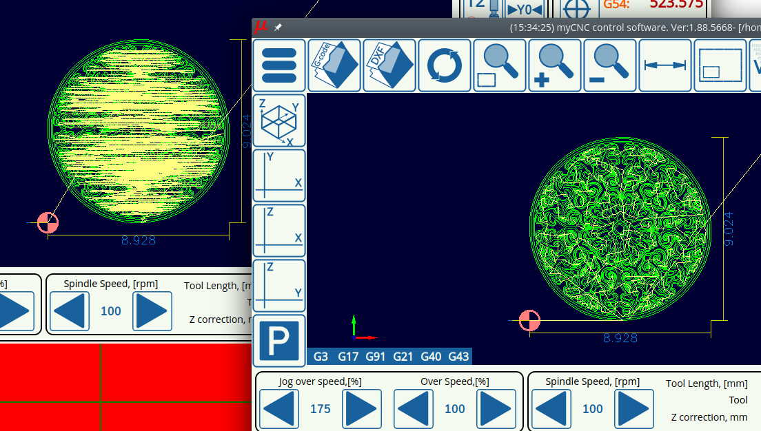
The DXF toolpath optimization toggle allows the myCNC software to optimize cut time in DXF/HPGL files by choosing the closest next cut as the program is running. This setting is usually left ON, as it allows to create a valid toolpath for a simple Photoshop file etc, however in case that the file you are importing already has a specified toolpath it can be toggled OFF so that the toolpaths do not conflict. See the screenshot below for a comparison of unoptimized versus optimized HPGL import:
Example of setting up DXF import functionality
In our example, we will be enabling DXF import for plasma cutting. Please note, that plasma cutting using DXF files is limited in functionality (lacking features such as kerf compensation, etc), and should not be used as a dedicated CAM software replacement.
1) Enable the checkmark in the Plasma line within DXF settings and disable other tabs (unless multiple tools are used):

2) A tab with plasma cutting settings should appear in the DXF import window, fill in the parameters such as feed and lead-in:
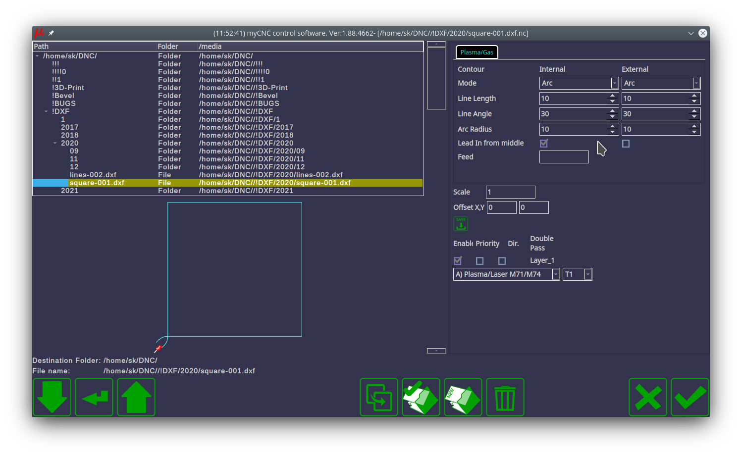
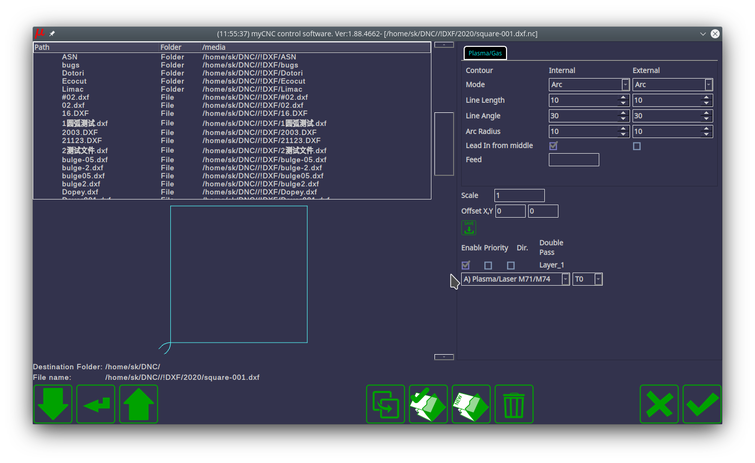
3) Assign the layer in which your part is drawn to the Plasma tool M71 / M74. Check the Enable checkbox for this layer:
Visualization
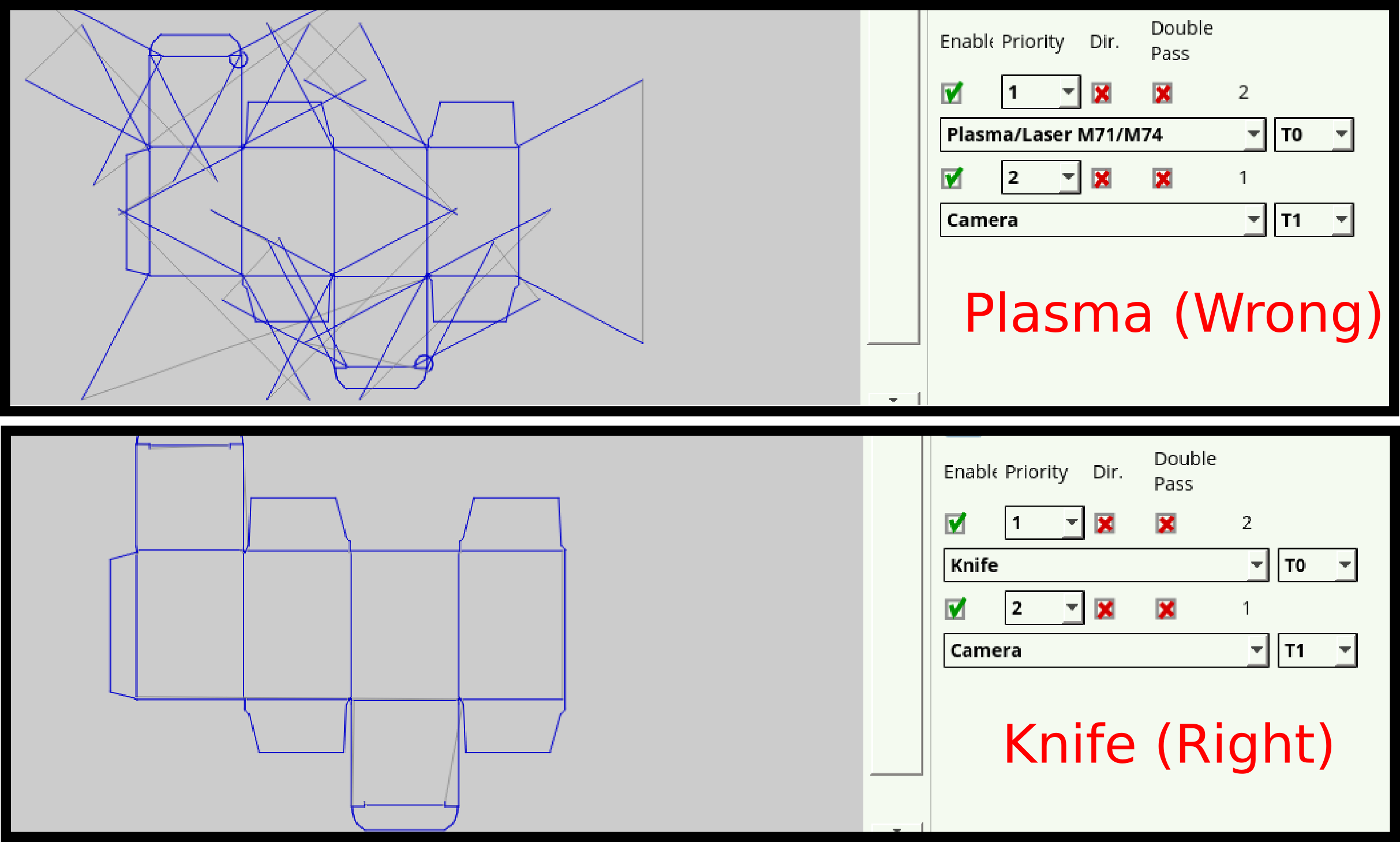
The visualization window serves as a visual indication for the user as to how the DXF file that is being imported will look. It also allows to catch some simple mistakes in file settings such as the wrong technology or the wrong priority being selected for each layer of the DXF file.
As an example, below is a visualization of a DXF file designed with a tangential knife in mind. If the tool has been incorrectly selected to be a plasma cutter, the visualization can serve as a useful reminder to the user:
DXF import settings configuration dialogue
For a full description of the DXF settings configuration dialogue, please consult the myCNC Configuration Dialogues page.
Segment Merge Tolerance
Segment Merge Tolerance has been introduced to fix an issue where the visualization at the Import screen would appear to have disconnected lines. For HPGL files this Tolerance value must be at least 0.03mm (as the files tend to contain integer values with a precision of approximately 0.025, and even with correct rendering, there may be discrepancies in rounding). For DXF files, this value depends on the original drawing method and the software used to design the file. Ideally, DXF files should work well with a Tolerance value of around 0.001mm, however the actual necessary value may be different depending on the imported files.
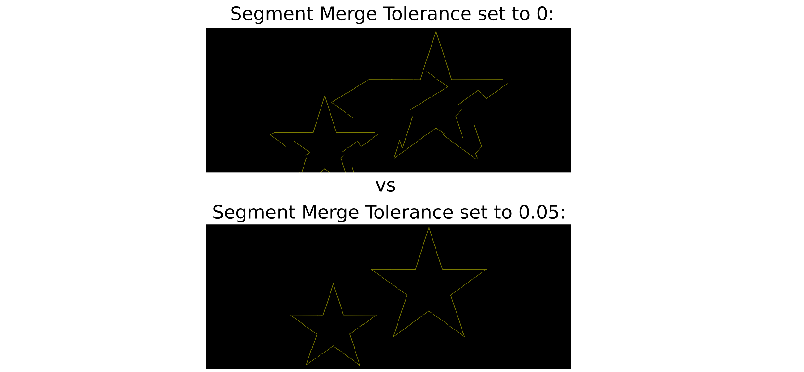
If this issue appears, a value of around 0.05 may be a good starting point to try and fix this visual problem.
DXF2-Import (Plasma Update)
For more info, see the CAM Module article.
The UI and functionalty overhaul for DXF import is available as of the late 2023. The highlights are as follows:
- For closed contours, a correction for the width of the cut (kerf) can now be considered - internal cutouts and external parts are taken into account
- For open contours, the system still follows a given toolpath
- Lead-in/lead-out editing, size, position and type of lead-in/lead-out adjustiments
- Ability to freely move, scale, mirror and rotate imported DXF file(s) in the CAM editor
- Cut Sequence functionality, allowing to change the cutting sequence for the imported files
- Ability to save/load existing CAM projects within the DXF Import window.
The video below showcases the functionality of DXF2-Import in more detail:
To enable the new DXF2 Import functionality:
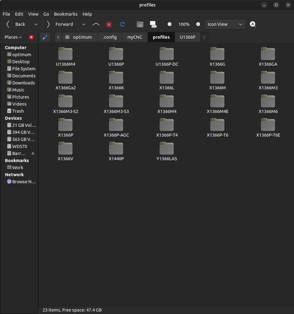
1. On your PC, open your profile folder (for plasma cutting, typically X1366P):
On Linux, this folder will be located in
/home/user_name/.config/myCNC/profiles...
On Windows, this folder will be located in
C:/Users/User_Name/myCNC/profiles...
Read more about myCNC profiles here: MyCNC profiles
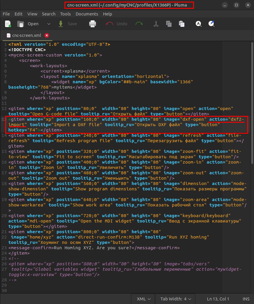
2. Within your current profile folder (for plasma cutting, this is typically X1366P), open the cnc-screen.xml file in your text editor of choice (Pluma by default on Ubuntu MATE).
3. Within the opened file, locate the following block of code:
<gitem where="xp" position="160;0" width="80" height="80"
image="dxf-open" action="dxf-import"
tooltip="Import a DXF file" tooltip_ru="Открыть DXF файл"
type="button" hotkey="F4"></gitem>
Note: The exact block of code may look slightly different (with regards to the position value, etc), with the important part being the dxf-import line.
Replace the section
action="dxf-import"
with
action="dxf2-import"
:
Save the file and close the text editor program.
4. Reload the myCNC software for the changes to take effect.
To switch back to the original DXF Import window, repeat the steps and replace the line back to action=“dxf-import”.
A video showcasing the steps to enable DXF2 Import:

