Table of Contents
G-Codes list
Below is a list of G-codes currently implemented in the myCNC system.
| G-codes | |||
|---|---|---|---|
| Code | Description | Mill (M) Lathe(L) Cutting table (C) | Comments |
| G00 | Rapid Positioning | 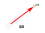 . See note on G53. . See note on G53. |
|
| G01 | Linear Interpolation | 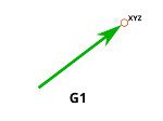 |
|
| G02 | Arc CCW Interpolation | 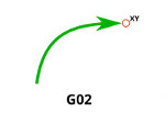 |
|
| G03 | Arc CW InterpolatioMotion Mode Canceln |  |
|
| G04 | Dwell | In milliseconds. Will prevent the axes from moving during the specified time period | |
| G5.1 | | ||
| G5.2 | | ||
| G5.3 | | ||
| G10 | Data Set | ||
| G11 | Mirror Cancel | ||
| G12 | Mirror X | ||
| G13 | Mirror Y | ||
| G14 | Mirror XY | ||
| G15 | Polar coordinates Off | ||
| G16 | Polar coordinates On | ||
| G17 | Plane XY | ||
| G18 | Plane ZX | ||
| G19 | Plane YZ | ||
| G20 | Set Units to Inches | ||
| G21 | Set Units to Metric | ||
| G28 | G28 Home | ||
| G28.1 | Home Position Set | ||
| G28.2 | Home Position #1 Save | ||
| G28.3 | Home Position #2 Save | ||
| G28.4 | Home Position #3 Save | ||
| G28.5 | Home Position #1 Restore | ||
| G28.6 | Home Position #2 Restore | ||
| G28.7 | Home Position #3 Restore | ||
| G28.9 | Home Position Address | ||
| G30 | G30 Home | ||
| G30.1 | G30 Home Set | ||
| G33 | Spindle Synchronization | ||
| G33 | Spindle Synchronization | ||
| G38.2 | G38.2 Probing | Probing codes G38.2-G38.5 are typically not used in myCNC systems, as their functions have been largely replaced and expanded by the PLC commands (specific probing M-codes) | |
| G38.3 | G38.3 Probing | ||
| G38.4 | G38.4 Probing | ||
| G38.5 | G38.5 Probing | ||
| G38.9 | Tool Measure | ||
| G40 | Tool Correction Cancel | 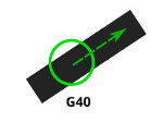 |
|
| G41 | Tool Correction Left | 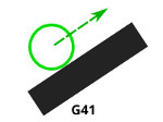 YouTube link |
|
| G42 | Tool Correction Right | 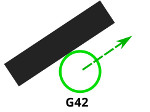 |
|
| G43 | G43 Tool Length Offset | ||
| G44 | G44 Tool Length Offset | ||
| G49 | G49 Cancel Tool Length Offset | ||
| G50 | G50 Scaling Cancel | M | |
| G51 | G51 Scaling Set | M | |
| G50 | G50 Set Max Spindle Speed (Lathe) | L | |
| G53 | Machine Coordinates | M L | The toolpath planner (as well as the the line/circle interpolation commands) work only in program coordinates. Therefore, the G53 code only works with G0 positioning commands. See note below on G53 & G0 usage. |
| G54 | Use Coordinate System #1 | M L | Coordinate system switching codes G54-G59 change the offset between machine and work coordinates. As the toolpath planner does not have access to these commands, it is necessary to position the tool in the new coordinate system after switching (using G0) |
| G55 | Use Coordinate System #2 | M L | |
| G56 | Use Coordinate System #3 | M L | |
| G57 | Use Coordinate System #4 | M L | |
| G58 | Use Coordinate System #5 | M L | |
| G59 | Use Coordinate System #6 | M L | |
| G59.1 | Use Coordinate System #7 | M L | |
| G59.2 | Use Coordinate System #8 | M L | |
| G59.3 | Use Coordinate System #9 | M L | |
| G59 | Set Hypertherm Power Source Parameters (Plasma Cutting table only) | ||
| G61 | | M | |
| G62 | | M | |
| G63 | | M | |
| G64 | | M | |
| G65 | G-code macro | M | |
| G73 | Cycle Deep Hole Drilling | M |  |
| G74 | Cycle Left Hand Tapping | M | |
| G76 | Cycle Lathe Thread | L | G76 Thread Cycle |
| G80 | Cancel Motion Mode | ||
| G81 | Cycle Drilling |  |
|
| G82 | Cycle Drilling Dwell | ||
| G83 | Cycle Peck Drilling | 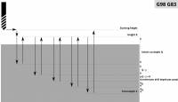 |
|
| G84 | Cycle Right Hand Tapping | ||
| G85 | Cycle Boring No Dwell Feed Out | ||
| G86 | Cycle Boring Spindle Stop Rapid Out | ||
| G87 | Cycle Back Boring | ||
| G88 | Cycle Boring Spindle Stop Manual Out | ||
| G89 | Cycle Boring Dwell Feed Out | ||
| G90 | Absolute Programming | ||
| G91 | Incremental Programming | ||
| G90.1 | Arc Center Absolute Programming | ||
| G91.1 | Arc Center Incremental Programming | ||
| G92 | Set Work Position | M | |
| G92 | Lathe Thread | L | For example, G92 S3300 will set a max spindle speed of 3300 in the constant cutting speed mode |
| G94 | Feedrate Per Minute | L | |
| G95 | Feedrate Per Revolution | ||
| G96 | Lathe Surface Speed | L | Constant surface speed for a lathe with a given speed. For example, G96 S220 M3 will set system to constant cutting speed mode at 220 units/min |
| G97 | Set Spindle Speed | L | (revolutions per minute) |
| G98 | Turn Feedrate per Minute | L | |
| G98 | Canned Return Back to initial height | M | On mill machines, G98 allows to return the tool back to initial height Z during the canned return process.  |
| G99 | Turn Feedrate per Revolution | L | |
| G99 | Canned Return to a set height | M | As opposed to G98, which returns the tool to the initial height (height before cutting), G99 returns the tool to some set height Z.  |
| G130 | Experimental feature - select a specific cutcharts mode from within a G-code program (for example, G130 P217 will select mode #217) | ||
| G131 | Cut on/off. The P parameter loads in different cutting modes. | G131 P0 - disable, G131 P1….16 - enable the corresponding mode. Power control (DAC-PWM) is activated accordingly per mode. | |
| G150 | Tool Correction Radius Set | ||
| Miscellaneous M-codes | |||
| Code | Description | Implementation | Comments |
| M00 | | ||
| M01 | Optional Stop | PLC | |
| M02 | End Program | Native + PLC | |
| M03 | Spindle On CW | PLC | |
| M04 | Spindle On CCW | PLC | |
| M05 | Spindle Stop | PLC | |
| M06 | Change Tool | Macro | |
| M07 | Mist On (Cutting On) | PLC | |
| M07 | Plasma Dot Marking | PLC | |
| M08 | Flood On (Cutting On) | PLC | |
| M08 | Plasma table - Drill Marking | PLC | |
| M09 | All Coolant Off (Cutting Off) | PLC | |
| M14 | THC Off | Native + PLC | Cutting tables |
| M15 | THC On | Native + PLC | Cutting tables |
| M19 | Spindle Orientation On | PLC | Lathe |
| M20 | Spindle Orientation Off | PLC | Lathe |
| M20 | Start Cutting | PLC | Cutting Tables |
| M21 | Stop Cutting | PLC | Cutting Tables |
| M23 | Thread Finishing ON | PLC | Lathe |
| M24 | Thread Finishing OFF | PLC | Lathe |
| M30 | End Program with Rewind Pointer | Macro | |
| M41 | Set Low Gears | PLC | |
| M41 | Set High Gears | PLC | |
| M45 | Start Plasma Marking | PLC | Cutting Tables |
| M46 | Stop Plasma Marking | PLC | Cutting Tables |
| M50 (1) | THC Off | PLC | Cutting Tables |
| M50 (2) | Hypertherm HPR source Off On-the-fly | Native + PLC | Cutting Tables |
| M50 (3) | Feed Override On/Off | Native + PLC | |
| M51 | THC On | PLC | Cutting Tables |
| M62 | Turn On binary output pin | PLC | |
| M63 | Turn Off binary output pin | PLC | |
| M64 | Turn On binary output pin | PLC | |
| M65 | Turn Off binary output pin | PLC | |
| M71 | Start Cutting YouTube video | PLC | Cutting Tables |
| M72 | Begin Plasma Marking Section | PLC | Cutting Tables |
| M73 | End Plasma Marking Section | PLC | Cutting Tables |
| M74 | Stop Cutting | PLC | Cutting Tables |
| M75-M88 | User defined M-codes (Section 1) | ||
| M92 | Start Cutting | PLC | Cutting Tables |
| M93 | Stop Cutting | PLC | Cutting Tables |
| M89 | Start Marking | PLC | Cutting Tables |
| M90 | Stop Marking | PLC | Cutting Tables |
| M98 | Subroutine Run | Native | Cutting Tables |
| M99 | Subroutine End | Native | Cutting Tables |
| M101-199 | User defined M-codes (Section 2) | ||
| M200-999 | User defined M-codes (Section 3) | ||
| M421 | Tool Length Measure | ||
| M422 | Tool Breakage Check | ||
| M440-M470 | Probing tool macros (locating surface, edges, etc) | ||
| Misc Macros | |||
| Code | Description | Implementation | Comments |
| Homing | |||
| M131 | Homing X axis | Macro | |
| M132 | Homing Y axis | Macro | |
| M133 | Homing Z axis | Macro | |
| M134 | Homing A axis | Macro | |
| M135 | Homing B axis | Macro | |
| M136 | Homing C axis | Macro | |
| M138 | Homing All axes | Macro | |
G10 Data Set
G10 L P Q X Y Z A B C U V W
- G10 - data set
- L - code operation
- P - Parameter #1
- Q - Parameter #2
- X,Y,Z,A,B,C,U,V,W - coordinates/values
- L2 - set an offset between program and machine coordinates. P1 to P9 for coordinate systems G54 to G59.3
G10 L2 P1 X1 Y1 Z1 (Set G54 offset X to 1, Y to 1, Z to 1)
- L70 - set position to given values
- P0 - Set Machine Position to given values
G10L70 P0 X0 Y0 (Set Machine coordinates X=0, Y=0)
- P1 - Set Work Position in G54 Coordinates system to given values
G10L70 P1 X10 Y20 Z30 (Set G54/Work coordinates X=10, Y=20, Z=30)
G10L70 P1 X0 Y0 Z0 A0 B0 C0 (Set G54/Work coordinates X=0,Y=0,Z=0,A=0,B=0,C=0)
- P2 - Set Work Position in G55 Coordinates system to given values
G10L70 P2 X0 Y10 Z20 (Set G55/Work coordinates X=0, Y=10, Z=20)
G10L70 P2 X0 Y0 Z0 A0 B0 C0 (Set G55/Work coordinates X=0,Y=0,Z=0,A=0,B=0,C=0)
- P3 - Set Work Position in G56 Coordinates system to given values
G10L70 P2 X0 Y10 Z20 (Set G56/Work coordinates X=0, Y=10, Z=20)
G10L70 P3 X0 Y0 Z0 A0 B0 C0 (Set G56/Work coordinates X=0,Y=0,Z=0,A=0,B=0,C=0)
- P4 - Set Work Position in G57 Coordinates system to given values
G10L70 P4 X0 Y10 Z20 (Set G57/Work coordinates X=0, Y=10, Z=20)
G10L70 P4 X0 Y0 Z0 A0 B0 C0 (Set G57/Work coordinates X=0,Y=0,Z=0,A=0,B=0,C=0)
- P5 - Set Work Position in G58 Coordinates system to given values
G10L70 P5 X0 Y10 Z20 (Set G58/Work coordinates X=0, Y=10, Z=20)
G10L70 P5 X0 Y0 Z0 A0 B0 C0 (Set G58/Work coordinates X=0,Y=0,Z=0,A=0,B=0,C=0)
- P6 - Set Work Position in G59 Coordinates system to given values
G10L70 P6 X0 Y10 Z20 (Set G59/Work coordinates X=0, Y=10, Z=20)
G10L70 P6 X0 Y0 Z0 A0 B0 C0 (Set G59/Work coordinates X=0,Y=0,Z=0,A=0,B=0,C=0)
- P7 - Set Work Position in G59.1 Coordinates system to given values
G10L70 P7 X0 Y10 Z20 (Set G59.1/Work coordinates X=0, Y=10, Z=20)
G10L70 P7 X0 Y0 Z0 A0 B0 C0 (Set G59.1/Work coordinates X=0,Y=0,Z=0,A=0,B=0,C=0)
- P8 - Set Work Position in G59.2 Coordinates system to given values
- P9 - Set Work Position in G59.3 Coordinates system to given values
- Current coordinates number is stored in Global variables register #5220. This register can be used to set Work coordinates in the Current Coordinates System
G10L70 P#5220 X0 Y10 Z20 (Set The Current Work coordinates X=0, Y=10, Z=20)
G10L70 P#5220 X0 Y0 Z0 A0 B0 C0 (Set The Current Work coordinates to X=0,Y=0,Z=0,A=0,B=0,C=0)
- L80 - Assign value from Q to Register Address P
G10L80 P100 Q10 (//Assign "10" to Register #100 // #100=10 //)
- L81 - Copy value from Register Address Q to Register Address P
G10L81 P100 Q10 (//Assign a value of Register #10 to Register #100 // #100=#10 //)
- L180 - Add Q value to Register Address P and store the result to Register Address P
G10L180 P100 Q10 (//Add 10 to Register #100 // #100=#100 + 10 //)
- L181 - Subtract Q value from Register Address P and store the result to Register Address P
G10L181 P100 Q10 (//Subtract 10 from Register #100 // #100=#100 - 10 //)
- L182 - Mul Register Address P by Q value and store the iresult to Register Address P
G10L182 P100 Q10 (//Multiply Register #100 by 10 // #100=#100 * 10 //)
- L183 - Divide Register Address P to Qvalue and store the result to Register Address P
G10L183 P100 Q10 (//Divide Register #100 by 10 // #100=#100 / 10 //)
- L184 - Binary AND value Q with Register Address P and store the result to Register Address P
G10L184 P100 Q66 (//Binary AND Register #100 with 66 // #100=#100 & 66 //)
- L185 - Binary OR value Q with Register Address P and store the result to Register Address P
G10L185 P100 Q66 (//Binary OR Register #100 with 66 // #100=#100 | 66 //)
- L186 - Binary XOR value Q with Register Address P and store the result to Register Address P
G10L186 P100 Q77 (//Binary XOR Register #100 with 77 // #100=#100 ^ 77 //)
- L190 - Add value from Register Address Q with Register Address P and store the result to Register Address P
G10L190 P100 Q101 (//Add Register #100 with Register #101 // #100=#100 + #101 //)
- L191 - Subtract value from Register Address Q from Register Address P and store the result to Register Address P
G10L191 P100 Q101 (//Subtract Register #101 from Register #100 // #100=#100 - #101 //)
- L192 - Mul value from Register Address Q by Register Address P and store the result to Register Address P
G10L192 P100 Q105 (//Multiply Register #100 by Register #105 // #100=#100 * #105 //)
- L193 - Divide value from Register Address P to Register Address Q and store the result to Register Address P
G10L193 P100 Q101 (//Divide Register #100 to Register #101 // #100=#100 / #101 //)
- L194 - ABS calculate absolute value of Register Address P and store the result to Register Address P
G10L194 P100 (//Absolute value of Register #100 // #100=ABS(#100) //)
- L200 - trigonometric functions support, a command with the format “P_reg1 Q_reg2” where Register Address reg1 = sin(reg2)
- L201 - reg1 = cos(reg2)
- L202 - reg1 = tan(reg2)
- L203 - reg1 = asin(reg2)
- L204 - reg1 = acos(reg2)
- L205 - reg1 = atan(reg2)
G92/G96 for lathe cutting
In a lathe system, G92 is used to set the maximum spindle speed (in the constant cutting speed mode), while G96 sets a constant surface cutting speed. In the code below,
N17 G97 S2500 M3
N18 G0 X14 Z1
N19 G92 S2500
N20 G96 S220 M3
the G92 line will set the maximum speed to 2500 rpm, while the G96 line will switch the system to a 220 m/min constant cutting speed mode.
In this mode, the spindle speed is recalculated depending on the current diameter (the current X coordinate).
The rotation speed changes depending on the diameter, so that the cutting tool moves along the surface at a set speed of 220 meters/min. The larger the diameter, the slower the system will rotate the part, and if the diameter is smaller, then the rotation speed will increase. By this logic, the rotation speed can go to infinity when the diameter reaches 0, so G92 is used to set a maximum value.
In a lathe configuration, both G92 and G50 work the same way if the “S” parameter is used. If the G92 command features an F-code parameter however, then the command is treaded as a threading command.
For example,
G92 S2500
and
G50 S2500
should produce the same result (although some users may prefer G92 due to the general convention). However, a command such as
G92 Z-12 X10 F1
G92 Z-12 X20 F1 L2 P99
is automatically recognized by the system as a threading command instead.
M07 - Plasma Dot Marking
M07 is used as Plasma Dot Marking. Dot Marking procedure is -
- Plasma Torch moves down till probe sensor activated
- The torch moves up to Ignition Height
- Plasma Power source is turned ON
- System wait Dot Time which is sum of Plasma Power Source Delay Time and Dot Time
- Plasma Power source is OFF
- Torch moves up to 20mm
M07 PLC procedure source code is below
- M07.plc
#include pins.h
#include vars.h
#include func_ihc.h

main()
{
  portclr (OUTPUT_MARKER1);
  portclr (OUTPUT_MARKER2);

  do_plasma_probe();

  if (marker_ihc_dot_height<10) {marker_ihc_dot_height=10;}; //fix dot height parameter is not correct

  gvarset(7080,ihc_move_down_speed);//set speed;

  g0moveA(0x0,0x4,marker_ihc_dot_height); //Z axis, ignition_height
  timer=200;do{ timer--; }while(timer>0); //wait 0.1sec till motion started
  do { code=gvarget(6060); }while(code!=0x4d);//wait till motion finished

  portset(OUTPUT_PLASMA); //PLASMA ON
  portset(OUTPUT_MARKER1);

  timer=marker_dot_time; //dot time
  timer=timer+marker_dot_delay; do{ timer--;}while(timer>0); //dot time delay

  portclr(OUTPUT_PLASMA); //PLASM OFF
  portclr(OUTPUT_MARKER1);

  g0moveA(0x0,0x4,2000); //Z axis, ignition_height 20mm up
  timer=200;do{timer--;}while(timer>0); //pause 0.1sec for motion starts
  do { code=gvarget(6060); }while(code!=0x4d);//wait till motion finished

  proc=plc_proc_idle;
  exit(99);
};
M08 - Plasma cutting table - Drill Marking
M08 is used for Drill Marking operations on Plasma Cutting machines which have drill head. Drill Marking procedure is the following:
- Drill Head Cylinder and Drill Power turned ON
- Drill Head moves down on Probing Speed until Drill probe sensor activated
- Moving speed switched to Drill Speed and the Head move lower to programmed Drill Depth
- Drill Head moves up to Lift Height
- Drill Head Cylinder and Drill Power turned OFF
M08 PLC source code example is shown below
- M08.plc
#include pins.h
#include vars.h
main()
{
  portset(OUTPUT_DRILL_VALVE);
  portset(OUTPUT_DRILL_POWER);

  gvarset(7080,drill_probe_speed ); //set speed;
  timer=200;do{timer--;}while(timer>0); //wait till drill head down

  sens=portget(INPUT_DRILL);
  if (sens==0)
  {
    g0moveA(0x0,0x4,0-30000); //Z axis
    timer=200;do{timer--;}while(timer>0); //wait till motion started
    do{
        code=gvarget(6060);
        sens=portget(INPUT_DRILL);
        if (sens!=0)
        {
          code=1;
          message=PLCCMD_LINE_STOP;//skip line
        };
      }while (code==0);
      do { code=gvarget(6060); }while(code!=0x4d); //wait till motion finished
  };

  gvarset(7080,drill_speed);//set speed;
  if (drill_depth>50)
  {
    depth=0-drill_depth;
    g0moveA(0x0,0x4,depth);  //Z axis
    timer=200;do{timer--;}while(timer>0);   //wait till motion started
    do{code=gvarget(6060);}while(code!=0x4d);//wait till motion finished
  };

  gvarset(7080,1000);//set speed up;

  if (drill_lift_height<100)
  {
    drill_lift_height=100;
  };

  g0moveA(0x0,0x4,drill_lift_height);   //drill head lift height
  timer=200;do{timer--;}while(timer>0); //wait till motion started
  do { code=gvarget(6060); }while(code!=0x4d); //wait till motion finished

  portclr(OUTPUT_DRILL_VALVE);
  portclr(OUTPUT_DRILL_POWER);

  exit(99);
};
M45 - Start Plasma Marking
M45 - Start Plasma Marking is implemented through Hardware PLC procedure. The M45 source example is listed below. Functions should be described in include files “func_ihc.h” and “func_plasma.h”
- do_plasma_probe();
- do_move_ignition_height();
- do_wait_plasma();
- do_move_pcutting_height();
- M45.plc
#include pins.h
#include vars.h
#include "func_ihc.h"
#include "func_plasma.h"

main()
{

    portclr (OUTPUT_MARKER1);
    portclr (OUTPUT_MARKER2);

    do_plasma_probe();
    do_move_ignition_height();

    portset(OUTPUT_PLASMA);
    portset(OUTPUT_MARKER1);

    do_wait_plasma();
    do_move_cutting_height();

    texit=timer+ihc_pierce_time;
    do{timer++;}while(timer<texit);

    start_thc();

    //set OK message and exit
    proc=plc_proc_plasma;
    message=PLC_MESSAGE_PLASMA_OK;
    exit(99);
};
G0G53 vs G1/G2/G3 commands
Keywords: Simulator Displacement Error, Critical Compiler Stop.
When using G0G53 commands in machine coordinates, the controller switches to the machine coordinate position and the program coordinates become undefined at that given moment as a result. This means that the G1/G2/G3 interpolation commands cannot be used under these circumstances (instead, G0 must be used).
Therefore, after such a switch, it is necessary to first give a positioning command using G0. This command must be given for those axes that were used as machine axes so that the controller can apply the appropriate offsets for the program coordinates.
For example, this issue will occur when a macro present within a G-code program will contain G0G53 commands (for instance, the M6 tool change macro), after which the G1/G2/G3 interpolation is used immediately. To go further with this example, the user CANNOT use the following combination:
M6T1 (in this example, M6 utilizes G0G53)
G1 Z5
G1 Y5 X5
The code above will lead to a simulator displacement error. Instead, for the example above, the following code must be used:
M6T1 (in this example, M6 utilizes G0G53)
G0 Z5
G0 Y5 X5
In this second code example, as the tool change macro uses G53 G0 XYZ, the first movement after a tool change will be G0 (for XYZ). This can either be done in G-code (via a post-processor which will correctly output G0 instead of G1 for that section), or within the tool change macro itself.
