This is an old revision of the document!
Table of Contents
Linear encoder closed-loop setup
Read more about the topic in the MyCNC closed loop configuration manual.
Linear encoders are typically used on higher-end machines to allow for a more precise monitoring of the difference between the real and the expected machine position (incremental change from the absolute position). This article focuses on the linear encoder setup and on the methods to make the information obtained from the encoders useful within the myCNC software.
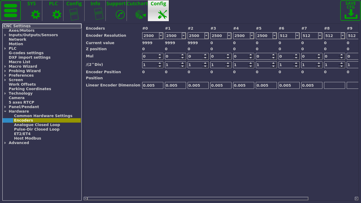
The following window is available upon navigating to Settings > Config > Hardware > Encoders:
The following settings are available:
- Encoder resolution for each particular encoder number.
- The current encoder value is displayed on this screen. This is the fastest way to check if the encoder is connected/working - for example, turning an MPG wheel handle should immediately change the current encoder value in this field for the selected encoder.
- Z-position
- Mul coefficients (multiplication value), and
- /(2^Div). These Mul and Div coefficients are used due to the fact that the controller cannot handle floating number data in calculations, therefore it is necessary to first multiply and then divide a number by certain coefficients. They are used to bring the value of the encoder in line with the pulses/unit value specified in the Axes/Motors tab. Larger numbers allow to reduce the error. For example, if the ratio between the Axes/Motors value and the encoder pulse/unit value is 3.5, then the multiplication value (Mul) can be set to 7, while Div can be set to 1 (2^1 =2, 7/2 = 3.5).
- Encoder position
- Position
- Linear encoder dimension. This should be set to the proper encoder dimension to convert the impulses from a linear encoder to mm (the most common values for this setting are 1 and 5 micrometers, as shown in the screenshot).
The following global variables deal with encoder values:
| 9000 | (+16) Registers represent Encoder values. Writing to this registers does not affect anything. Selected channel Current Encoder value will be returned when reading these registers. Reading these registers from the controller Hardware PLC will return actual Encoder value. Encoder values in the software are updated about every 128ms. This delay should be counted when using Encoder values from the Software PLC. 9000 - Encoder #0 value 9001 - Encoder #1 value 9002 - Encoder #2 value 9003 - Encoder #3 value 9004 - Encoder #4 value 9005 - Encoder #5 value 9006 - Encoder #6 value 9007 - Encoder #7 value |
| 9200 | +16. Reserved to display the encoder position on an infinite scale (no value turnover on every full encoder turn, instead the value will keep climbing indefinitely into the positives/negatives depending on where the encoder handle is spun) |
| 9216 | +16. Reserved to display the encoder position on an infinite scale WITH the current encoder dimension (to indicate the current encoder position) |
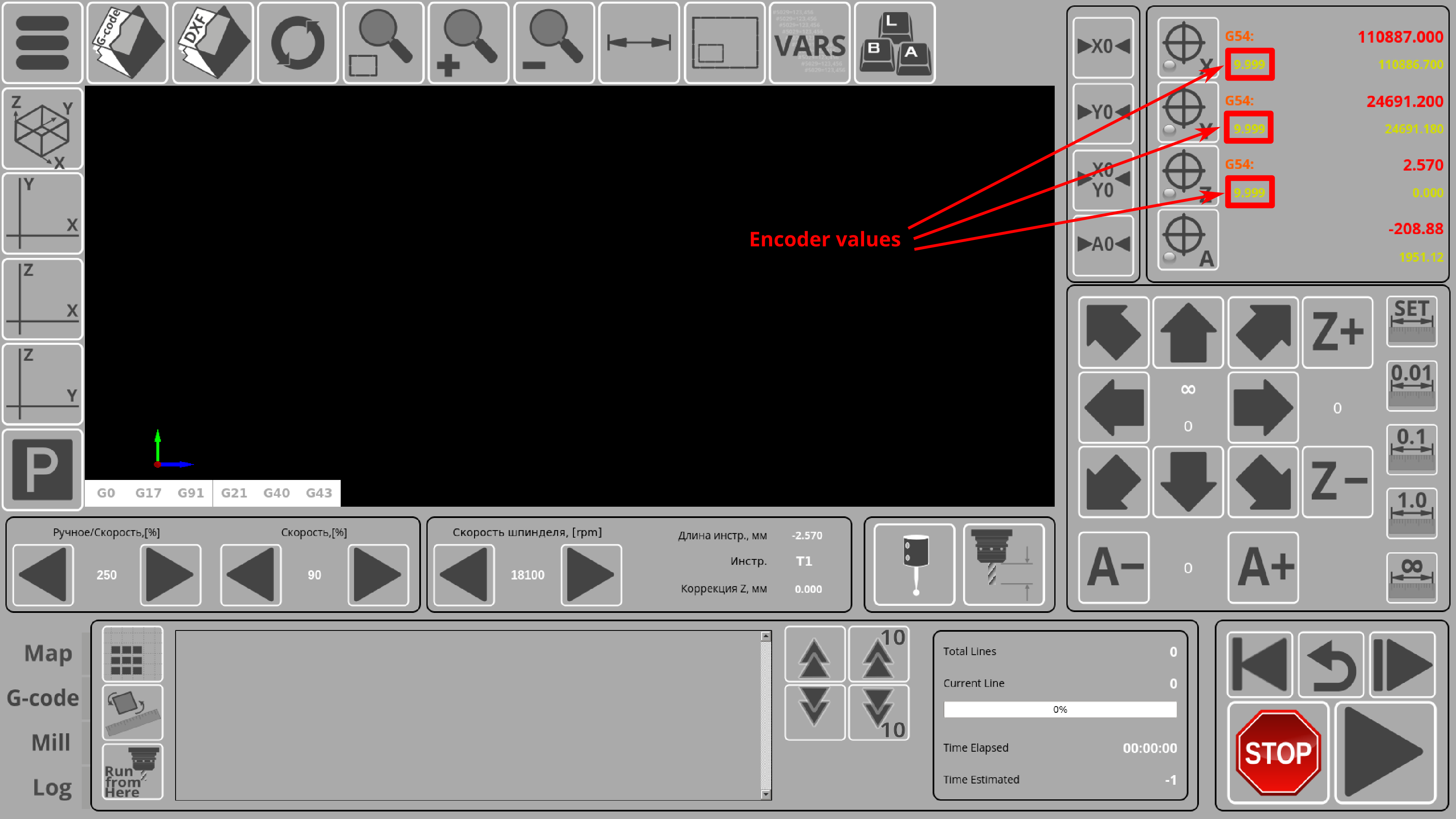
These global variables allow to display encoder values on the main screen of myCNC profiles that are geared towards encoder setups (such as 1366M4E and 1366PE):
Step-by-step setup example
THIS SECTION OF THE MANUAL IS A WORK-IN-PROGRESS. Please contact the myCNC Support Team should any questions arise.
Going through the setup process for linear encoder feedback:
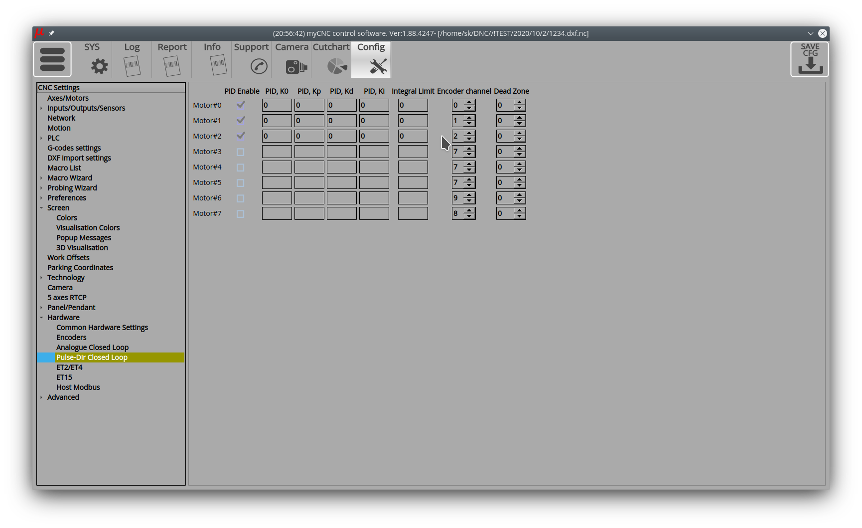
1. At this point, the PID number, motor output and encoder channel number should be respectively equal. I.e - PID0, Motor0, Encoder0 PID1, Motor1, Encoder1 PID2, Motor2, Encoder2
It is possible to customize arbitrarily, but so far it is strongly discouraged.
2. Registers for displaying the magnitude of the PID mismatch error - 9016, 9017, 9018, 9019 … and so on for PID 0, 1, 2, 3 … respectively
3. Baseline Profile for Ruler, Feedback and PID - X1366M4E
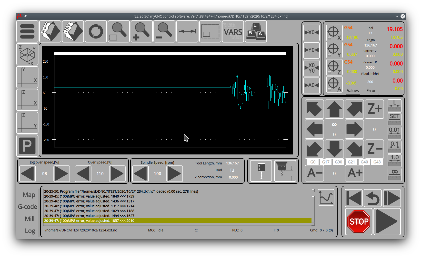
For PID tuning, it is recommended to output these registers to display the error value on the error indicator and on the corresponding “oscillograms”
Now the XML settings in the profile are different, the version will be updated. For those who have a profile already in work and a complete update is difficult, you need to make changes manually
4. Error magnitude display, coordinates-4.xml file
<!--Encoder values -->
<gitem where="x-coordinates" position="74;40" width="120" height="30"  displayAlignment="left;vcenter"
 fgColor="##f-machinepos" format="%8.3f" fontFamily="Open Sans" fontSize="16" type="display" deviation="0.0005"
 name="display-cnc-gvariable-9016"
 tooltip="Encoder error value for axis X"
 bgColor="##b-display" displayWidth="120" fontStyle="bold"></gitem>

<gitem where="x-coordinates" position="74;100" width="120" height="30"  displayAlignment="left;vcenter"
 fgColor="##f-machinepos" format="%8.3f" fontFamily="Open Sans" fontSize="16" type="display" deviation="0.0005"
 name="display-cnc-gvariable-9017"
 tooltip="Encoder error value for axis Y"
 bgColor="##b-display" displayWidth="120" fontStyle="bold"></gitem>

<gitem where="x-coordinates" position="74;160" width="120" height="30"  displayAlignment="left;vcenter"
 fgColor="##f-machinepos" format="%8.3f" fontFamily="Open Sans" fontSize="16" type="display" deviation="0.0005"
 name="display-cnc-gvariable-9018"
 tooltip="Encoder error value for axis Z"
 bgColor="##b-display" displayWidth="120" fontStyle="bold"></gitem>

<gitem where="x-coordinates" position="74;200" width="120" height="30"  displayAlignment="left;vcenter"
 fgColor="##f-machinepos" format="%8.3f" fontFamily="Open Sans" fontSize="16" type="display" deviation="0.0005"
 name="display-cnc-gvariable-9019"
 tooltip="Encoder error value for axis A"
 bgColor="##b-display" displayWidth="120" fontStyle="bold"></gitem>
In the current version, registers 9232, 9233, … were used at this location.
five. Display of the following error graphs X-bottab-left-mill.xml file The type myscope is responsible for displaying oscillograms Find and correct for displaying 3 graphs on one oscillogram with variables 9016, 9017, 9018 - for errors PID0, PID1, PID2
<gitem where="x-graph" position="10;10" width="880" height="380"
 name="myscope1" type="myscope" yrange="-300;300" K="1"
 source="cnc-gvariable-9016;cnc-gvariable-9017;cnc-gvariable-9018" sampling="50" />
6. In order for registers 9016, … to show an error, the PID must be enabled.
This requires 2 steps - 1) Check enable in the PID settings pullse-dir closed-loop 2) Start the Servo-ON procedure by writing “1” to register 60000
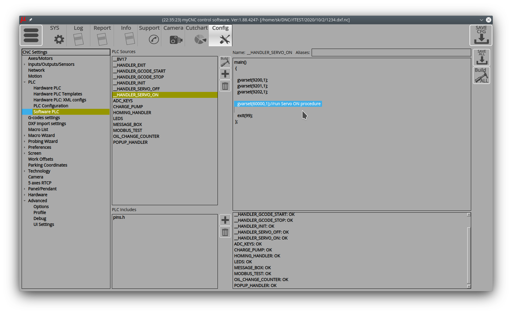
gvarset (60000,1); // run Servo ON procedure
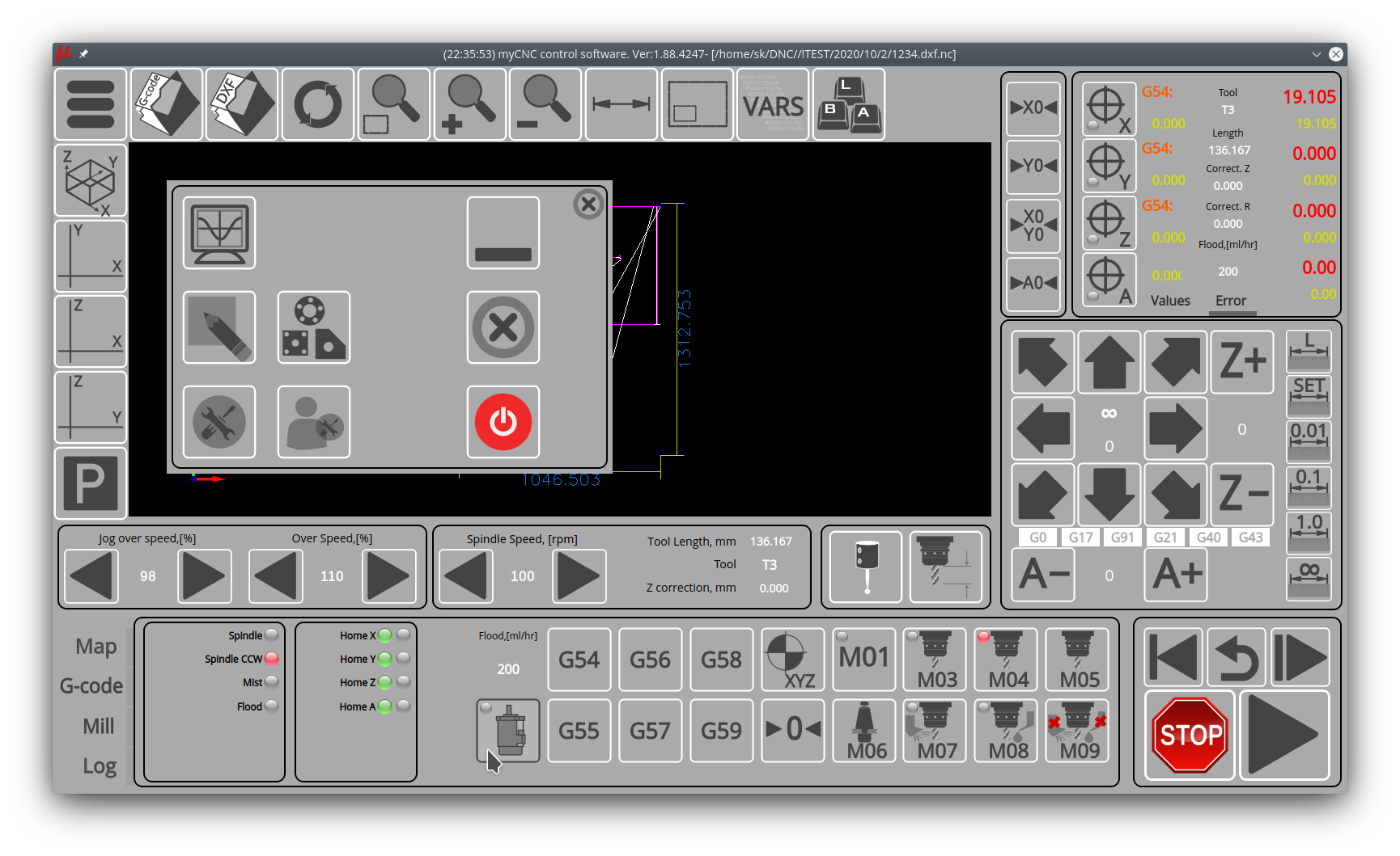
For automatic inclusion, this line can be added to HANDLER_INIT For manual start, there is a Servo-ON button, which, in turn, starts the HANDLER_SERVO_ON procedure And in it, in turn, there is a necessary entry in the register (after some other actions, for example, to include Servo-ON signals on drives, etc.)
By means of a multiplier and a divider, the “software” resolution of the linear encoder must be brought to the “pulse-per-mm” resolution. The controller will then operate with this program value. That is, in the “Linear Encoder Dimension” field, you must specify the resolution taking into account these factors and divisors.
(If the PIDs are turned off and not used, but you just need to have a position indication, then other registers are used for display, the multiplier and divider fields are not used, and then the real resolution of the ruler is indicated in the “Linear Encoder Dimension”. In general, in this place it turned out very unobvious setting, if we figure out how to do it more clearly, we will redo it)
Now also write the correct “K” for displaying graphs and error values.

