This is an old revision of the document!
Table of Contents
MyCNC Configuration Dialogs
Preferences Tab
Common

- Character Encoding. -
myCNC software uses Unicode Text encoding system. If input g-code files contain symbols encoded in other Encoding system, this system should be set in Character Encoding. combobox to show local symbols correctly in myCNC software
- NC code folders -
In File Open Dialog and DXF Import Dialog software search nc-files in folders provided in input lines NC code folders
For example, if set NC code folders as “~/DNC” and “/media” -

Only this folders will be available to open g-codes or dxf files -


Start/Stop

- Cutting ON commands
- Cutting OFF commands
- Soft stop time
- Limit Stop time
- After Stop Handler (on developing)
- Check Soft Limits for the full toolpath -
(V) - (checked) - myCNC tests the full toolpath if any of toolpath points going outside of Working Area (Soft Limits test) and does not start running if it is true. However, for very long g-code files this testing may take a very long time.
( ) - (clear) - The software tests for Soft Limits only a part toolpath file (which is about 2000 lines).
- Toolpath Position checking, axes - The control software knows Current Tool Position and Current Program Position (the position when a program was stopped or start program position in case g-code just loaded). When Start button pressed myCNC tests for each selected axis if “Current Tool” and “Current Program” positions are the same and block running if Not.
For example, X and Y axes are selected to check for Plasma Cutting 
Screen

3D Visualisation

G-code settings

Profile
XML configuration

Macros
Macro List

Macro Wizard

Probing wizard
Probing config

Probing macro wizard

PLC Builder
Hardware PLC

Hardware PLC: XML configs

Software PLC

PLC Configuration

Axes/Motors

The main axes-motors parameters can be configured in the dialog
1. Enabled. Each of axes X,Y,Z,A,B,C,U,W,V can be enabled or disabled. If any axis is disabled the software ignores All coordinates for this axis and does not send any motion to this axis. It is convenient to disable axes you don't use on the machine.
2. Pulses per unit. This parameter set number of pulses controller sends to the motor drivers to move on 1 unit (the unit depends on CNC configuration can be either “mm” or “inch”)
3. MaxSpeed - CNC control will limit machine speed for each axis with this value. Note that MaxSpeed does not count override % value. Be caution if you use override values more than 100%
4. Backlash - Backlash value in units (mm/inch) for each axis
5. Axes Mapping - Toolpath planner uses this setting for tool motion speed calculation. Possible settings are-
- “X”, “Y”, “Z”, “U”, “V”, “W” - linear axes X, Y, Z, U, V, W
- “A1”, “B1”, “C1” - rotation around axes X, Y, Z. Tooltip makes a circle-like motion on a material surface while A/B/C axis turning. An example is a rotary table, 4th rotary axis.
- “A2”, “B2”, “C2” - tilt around axes X,Y,Z. Tooltip position is not changed while A/B/C axis turning. Tool orientation changed only. An example is rotating tangential knife or 3D plasma bevel head.
- “Linear axis” - additional linear axis (any linear axis which behaviour cannot be described as X/Y/Z/U/V/W axis)
- “Rotary axis” - additional rotary axis (any rotary axis which behaviour cannot be described as A/B/C axis)
6. Speed profile - additional settings to optimize Speed profile for rotary axes
- “Constant surface speed” - Tooltip is moving on the surface of turning material. Turning speed is calculated depends on given F-feedrate and cutting speed of tooltip on the surface (It's supposed Tooltip moving on the arc with radius depends on current XYZ position).
- “Slave Of XYZ” - Current speed calculated for X,Y,Z axes depends on given F-feed rate. Turning speeds for rotary axes adjusted to get synchronous motion.
- “Spherical correction” - Settings for 3D bevel cutting head and RTCP kinematic correction.
7. Scan along rotational axis - special purpose settings if Y-axis is used as a rotary axis for tube cutting configuration. Obsolete
8. Attach to axis. Any of 6/8 motor output can be attached to any axis. Here you can select what axis is used for every motor outputs.
9. Inversion - Put checkbox if need to change rotation direction for any axis.
For Dual axis configuration just attach one axis simultaneously to two (or more) motor outputs.
For example, on a picture Motor outputs #0 and #1 are used for X-axis.
Invertion is selected for Output #1, so both motors connected to Output#0 and Output#1
will be rotated simultaneously, but in opposite direction
Inputs/Sensors
Alarms

myCNC software supports a number of Alarm input.
Any of myCNC controller binary input can be programmed as Alarm input. Alarm inputs setup is available in Alarms configuration dialog. In the dialog -
- Each Alarm can be enabled or disabled
- Any binary input can be assigned as selected Alarm
- Input type Normally opened or Normally closed can be selected to the alarm.
MyCNC software has different Handlers for Alarm.
Emergency Button
If Emergency button Alarm is triggered, the myCNC software stops running any Motion program or Jogging and Run PLC Handler for Emergency alarm - “EST.plc” PLC procedure. “Emergency button pressed. Program stopped!” message will be shown in the messages list

A user can define any behaviour for Emergency Stop event like -
- Power off servo-drivers
- Power off Spindle/Plasma power source
- Switch Off coolant, mist, air
- etc.
PLC procedure “EST.plc” is available in PLC Builder/Hardware PLC

If Emergency button activated, all further Job running, or jogging will be locked.
“Emergency button pressed.” message will be shown on the main screen

Example of Emergency button configuration is shown in a picture below
- Emergency button is enabled
- Binary input #53 is used as an Emergency key
- Emergency button is Normally closed, an Emergency event will be activated if the button is open

Limits

 To configure software limits -
- Set “Soft Limits Enabled” checkbox
- Set checkboxes for each axis you like to enable software limits
- Set Minimum and Maximum range for each axis
- Press “Save” button to save the settings
It's possible to reduce jog speed near the limits. If operator jogs toward the software limit, jog speed will be reduced on given distance from limit to given value (in % of normal jog speed). To enable this option -
- Set “Jog slow down” checkbox
- for each axis -
- “Slow down distance” - distance from software limit when jog speed will be slow down
- “Slow down value, %” - Slow Jog speed (in % of normal jog speed)
- Press “Save” button to save the settings
For example
Slow distance = 50, Slow value= 20% -
If jog toward software limit and distance to limit less than 50mm,
jog speed will be 5 times less normal jog speed (20%)
Slow distance = 10, Slow value= 100%  -
No reducing speed (because slow value is 100% of jog speed)
Hardware limits can be configured in myCNC software besides of software limits. There is a limit switch for negative and positive direction for each axis reserved in myCNC software. Any switch can be enabled, assigned to any of CNC control board binary input and configured as “Normally Open” or “Normally Closed”. To enable hardware limit for selected axis -
- Choose the axis (X, Y, Z, A, B, C) and side (positive or negative) and set respected checkbox;
- Set binary input number where hardware limit connected;
- Choose sensor type “Normally Open” or “Normally closed” in Combobox;
- Press “Save” button to save the settings
Triggers

MPG through binary inputs

Jog through ADC inputs
This function is useful to set up a joystick in order to regulate the speed at which the machine's working tool moves through analog means, allowing for more granular controls.
In order to do so, go to CNC Settings > Config > Inputs/Outputs/Sensors > Jog through ADC inputs. The following screen will be presented to you:

On this screen, we can set up the joystick inputs to adhere to the physical configuration and specifications of the joystick.
After connecting the joystick to the ADC ports of the controller, we can open the System Diagnostics window to check the actual ADC inputs.


While on the system diagnostics screen, move the joystick around to check which axis corresponds to which ADC input channel. In this example, ADC2 corresponds to the y-axis, while ADC3 corresponds to the x-axis movements of the joystick. These values are inputted back on the Settings screen:

NOTE: If the axes for the joystick need to be inverted for any reason, this can be done in Settings > Config > Hardware > Common Hardware Settings

By moving the joystick the furthest it can go in all directions and noting the maximum and the minimum values, those can be set as the Max and Min range in settings. In this example, the joystick Min Range is equal to roughly 430 for both the x- and y-axis inputs, and is around 3820 for the Max Range of the x-axis and 3830 for the Max Range of the y-axis:

The Dead Zone is set to be from 2100 to 2150 for the joystick used in this example, as this is taken to be the zero position by letting the joystick return to its center. This value has a range so that small accidental movements of the joystick do not trigger the movement of the machine:

As this joystick does not drop to zero for its minimum range of inputs, it allows us to set up a failsafe in case the joystick is accidentally unplugged. In order to do so, both checkmarks for the Ignore Zero and the Ignore Max have been switched to green, and the Min Alarm and Max Alarm have been set to be slightly outside the Min and Max Ranges (however, the Min Alarm is ALWAYS set to be above zero in this case):

NOTE: Not all joystick controllers allow to set the failsafe Min Alarm properly.
Please consult your joystick manual to find out if the input values do not drop to zero
so that the failsafe can be set up correctly.
The full settings window then looks as follows:

I/O Expand cards mapping

ADC mapping

Technology
PWM PIDs

Plasma Cutting
Plasma settings

Hypertherm communication

Hypertherm diagnostics

Cutcharts

THC

Lathe

Tools

Spindle


- Spindle Speed, [rpm] - A minimum, maximum range of Spindle, a step value (current spindle speed will be increased/decreased by this value while pressing on-screen SpinBox Default Spindle Speed)
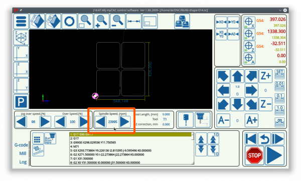
Maximum spindle speed value is used to adjust 0-10V analogue DAC output as well. - Spindle Overspeed, [%] - A minimum, maximum range of Spindle Overspeed, a step value (current spindle overspeed will be increased/decreased by this value while pressing optional on-screen SpinBox Spindle Overspeed). Both “Default Spindle Speed” and “Spindle Overspeed” can be used to adjust spindle speed on-the-fly, but there is a difference between parameters
- Default Spindle Speed will be overwritten while running next M3 Sxxxx or Sxxxx code. For instance, you change spindle speed to 12000rpm, then M3 S8000 comes from G-code, spindle speed will be changed to 8000rpm
- If you change Spindle Overspeed, [%] value, it will be applied for next Sxxxx code as well. For instance, current spindle speed is 5000rpm, you set “Spindle overspeed” to 120%, spindle speed increased up to 6000rpm (5000rpm*120%/100%). Then M3S8000 code comes from G-code program, spindle speed raised up to 9600rpm (8000rpm*120%/100%)
- Encoder channel. If feedback encoder is installed on the Spindle for threading, it might be configured in this position. Control boards ET5, ET10 have 6 encoder inputs (with hardware decoder), ET7 has 3 encoder inputs (hardware decoding as well). Encoder channel # should be configured here.
- Encoder pulsed per revolution. If Spindle Encoder feedback is used, the number of encoder pulses per spindle revolution should be set up here.
- Voltage offset, units - see below
- Voltage ratio, units - these two parameters are used to adjust DAC output voltage.
These parameters are active in case RS485/Modbus Communication is disabled
There is 12bit register is used for the DAC output. In theory, while writing values from 0 to 4095, the DAC output voltage is changed from 0 to 10V. A real maximum DAC voltage depends on the control board can be 11-12V. However, most of Spindle frequency inverters use 0-10V, there are many models on the market that use different voltage range for spindle speed control like 0-5V, 1-6V, 0-6V.
If spindle speed changed (PLC procedures M03, M04, SPN) the control software sends the to PLC procedures spindle speed value in eparam variable. The value is adjusted by the software by using the parameters offset and ratio. Eparam variable value can be calculated aseparam = Offset + 4095*(Spindle Speed)*Ratio/(Max Spindle Speed)
- If you don't need any adjustment, set Offset to “0” and Ratio to “1”.
- If you use spindle inverter with 0-5V range for instance, then you might need to set the Ratio to “0.5”
- For spindle range 1-6V you might need to set the Offset as well. Minimum voltage is “1V”, then Offset should be about 10% (1V of 10V) of 12bit range (4095), the Offset value is about “410”.
It's better to tune Offset and Ratio values by experiments with real VFD unit connected.
- RS485/Modbus communication. The checkbox enables communication with VFD through RS485/Modbus instead of analogue control.
- Spindle ratio (Modbus). If Modbus is enabled, the myCNC control software sends to PLC procedure variable eparam RAW spindle speed value (in rpm) multiplied by Spindle ratio (Modbus) parameter value.
- For instance, if Spindle speed is 10000rpm and Speed ratio (modus) is “1”, then eparam value will be “10000” (exact spindle speed).
- If the ratio variable is not enough to adjust Spindle speed register according to VFD type requirements, this can vbe made in PLC source.
- RS485 speed - RS485 communication baudrate selector
- Connection - RS485 connection configuration
- 8 or 7 bits
- No Parity, Odd or Even Parity
- 1 or 2 stop bits
- Inverter Address - up to 4 VFD can be connected through Modbus to arrange 4-spindle automatical polling. It needs to select the checkbox and set up Modbus ID for each VFD to enable VFD automatical polling
- Write Registers. For automatical Modbus polling registers, there are usually 2 control registers fo VFD.
- Frequency (SPidnel Speed) is changed by writing to “WR/Frequency” register
- Spindle control ON/OFF by writing some value to “WR/Operate” register.
Register addresses should be set up in these parameters
- Read Registers. VFD might have some status/diagnostic registers to read. The values may contain useful information like current power, current speed, temperature, errors, current status etc. You may select some register to automatical reading and show the value in this window.
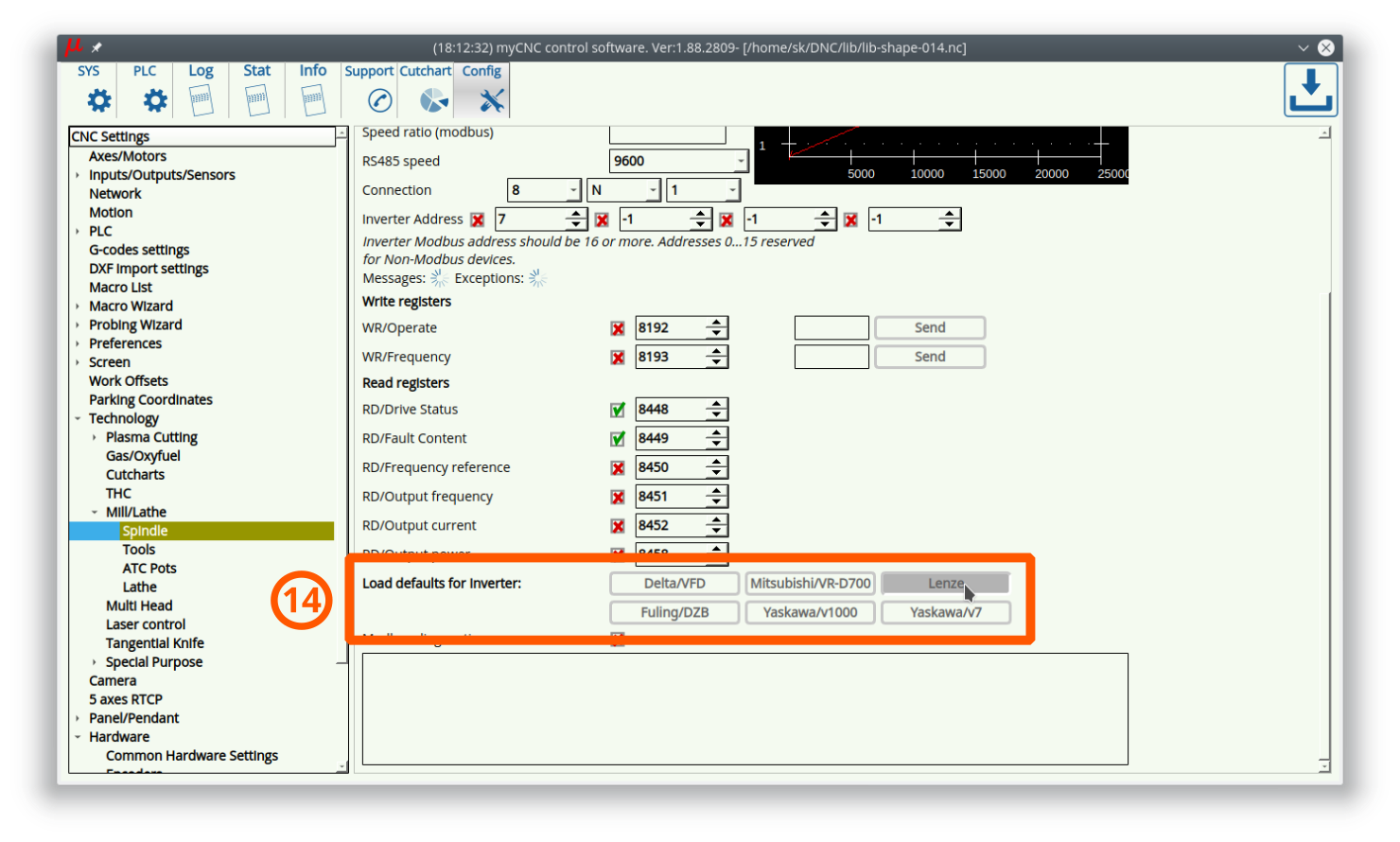
- “Write registers” and “Read registers” are different for different VFD manufacturers. We have pre-defined register addresses for the VFD inverters we tested. To set up register addresses just press the button with VFD type.


Gas/Oxyfuel

Multi Head

3D Printer

Multi-device

Multi-devices/Inputs

Multi-devices/Test

Multi-devices/PID Config

MaxLaser

Laser control

Circular Saw

Tangential Knife

Modbus Servo

Exhaust/Extraction control

Network

Camera

5 axes RTCP

Panel/Pendant
Wireless Pendant/XHC

Operator Panel

- Enable - Enable Operator Panel through Serial Port (UART) communication
- Serial Port - choose serial port Operator Panel connected
- Serial Speed - choose UART speed communication
- Serial Debug - Enable debug information while communication with operator panel.
ET7 Operator panel board id connected by default and does not use Serial communication settings above
- Key configuration settings
- Key Number Key ID
- Pressed - select checkbox to define Handler for Press event
- Release - select checkbox to define Handler for Release event (2 Handlers will be displayed if both Press and Release checkbox selected)
- Shift - select checkbox if Shift button should be pressed with the button to activate Handler
- Slot - Combobox with the Handler name
- Parameters - Optional parameters line for the Handler
Panel/Pendand/Hardkeys/Hotkeys Handler List
| Handler name | Description |
|---|---|
| CNC Action | Custom defined action |
| CNC Variable: Switch | Switch Global gariable value betweek given list of values. Parameters contain variable Number, “/“ separator, values list separated by ”;”. Example: CNC Variable: Switch Parameters: 5522/0.001;0.01;0.1;1.0;10 |
| CNC Variable: Toggle | Toggle Global gariable value. Parameter contains variable Number. Example: CNC Variable: Toggle Parameters: 5522 |
| CNC Variable: Change | Add to Global gariable value given “delta”. Parameter contains variable Number and Delta value separated by symbol “/“. Example: CNC Variable: Change Parameters: 5522/-0.2 CNC Variable: Change Parameters: 5522/0.01 |
| CNC Variable: Clear | Clear Global gariable value (=0). Parameter contains variable Number. Example: CNC Variable: Clear Parameters: 5522 |
| CNC Variable: Set | Set to “1” Global gariable value (=1). Parameter contains variable Number. Example: CNC Variable: Set Parameters: 5522 |
| CNC Variable: Assign | Assign Global gariable to given value. Parameter contains variable Number and the value separated by symbol ”/“. Example: CNC Variable: Assign Parameters: 5522/0.01 CNC Variable: Assign Parameters: 5522/0.1 CNC Variable: Assign Parameters: 5522/1.0 |
| File: Open | Show “File Open” dialog |
| File: Open DXF/HPGL | Show “DXF/HPGL File Open” dialog |
| File: Refresh | Reload current g-code file |
| Hardware: Direct Binary Set | Set given output pin (write “1”). Parameter contains Pin Number. Example: Hardware: Direct Binary Set Parameters: 15 |
| Hardware: Direct Binary Clear | Clear given output pin (write “0”). Parameter contains Pin Number. Example: Hardware: Direct Binary Clear Parameters: 15 |
| Hardware: Direct DAC Set | Write to DAC register given value. Parameters contain DAC Channel# and the value separated by symbol ”/“. Example: Hardware: Direct DAC Set Parameters: 0/2048 |
| Hardware: Direct PWM Set | Write to PWM register given value. Parameters contain PWM Channel# and the value separated by symbol ”/“. Example: Hardware: Direct PWM Set Parameters: 2/1024 |
| Hide: Custom widget by name | |
| Job: Play 1 line | |
| Job: Play 1 line backward | |
| Job: Run G-code | |
| Job: Run G-code with Confirmation | |
| Job: Start running | |
| Job: Start Cutting from Edge | |
| Job: Start running backward | |
| Job: Stop running | |
| Job: Reset current pointer | |
| Job: Back To Path | |
| Job: Skip Forward | |
| Job: Skip Backward | |
| Job: Skip Forward 10 | |
| Job: Skip Backward 10 | |
| Jog: X- | |
| Jog: X+ | |
| Jog: Stop X | |
| Jog: X- Y- | |
| Jog: X- Y+ | |
| Jog: X+ Y- | |
| Jog: X+ Y+ | |
| Jog: All Stop | |
| Jog: Y- | |
| Jog: Y+ | |
| Jog: Stop Y | |
| Jog: Z- | |
| Jog: Z+ | |
| Jog: Stop Z | |
| Jog: A- | |
| Jog: A+ | |
| Jog: Stop A | |
| Jog: B- | |
| Jog: B+ | |
| Jog: Stop B | |
| Jog: C- | |
| Jog: C+ | |
| Jog: Stop C | |
| Jog: X- && Key: | |
| Jog: X+ && Key: | |
| Jog: Y- && Key: | |
| Jog: Y+ && Key: | |
| Jog: Z- && Key: | |
| Jog: Z+ && Key: | |
| Jog: A- && Key: | |
| Jog: A+ && Key: | |
| Jog: B- && Key: | |
| Jog: B+ && Key: | |
| Jog: C- && Key: | |
| Jog: C+ && Key: | |
| Jog: Stop X | |
| Jog: Stop Y | |
| Jog: Stop Z | |
| Jog: Stop A | |
| Jog: Stop B | |
| Jog: Stop C | |
| Jog: Shift Set | |
| Jog: Shift Clear | |
| Jog: Shift Toggle | |
| Jog: Ctrl Set | |
| Jog: Ctrl Clear | |
| Jog: Ctrl Toggle | |
| Jog Speed Override: inc | |
| Jog Speed Override: dec | |
| Key Press: | |
| Key Release: | |
| (Dlg)Key Press: Shift | |
| (Dlg)Key Release: Shift | |
| (Dlg)Key Press: Up | |
| (Dlg)Key Press: Down | |
| (Dlg)Key Press: Left | |
| (Dlg)Key Press: Right | |
| (Dlg)Key Press: Escape | |
| (Dlg)Key Press: Enter | |
| (Dlg)Key Press: Dot | |
| (Dlg)Key Press: Delete | |
| (Dlg)Key Press: Backspace | |
| (Dlg)Key Press: 0 | |
| (Dlg)Key Press: 1 | |
| (Dlg)Key Press: 2 | |
| (Dlg)Key Press: 3 | |
| (Dlg)Key Press: 4 | |
| (Dlg)Key Press: 5 | |
| (Dlg)Key Press: 6 | |
| (Dlg)Key Press: 7 | |
| (Dlg)Key Press: 8 | |
| (Dlg)Key Press: 9 | |
| Move to Toolpath | |
| Parking Position: Save | |
| Parking Position: Move To | |
| Pendant: Axis (*) | |
| Pendant: Mul (*) | |
| Pendant: Wheel CW | |
| Pendant: Wheel CCW | |
| Pendant: Mul increment | |
| Pendant: Mul decrement | |
| Pendant: Axis change+ | |
| Pendant: Axis change- | |
| Pendant0: x0.001 | |
| Pendant0: x0.01 | |
| Pendant0: x0.1 | |
| Pendant0: x1 | |
| Pendant0: Axis Off | |
| Pendant0: Axis X | |
| Pendant0: Axis Y | |
| Pendant0: Axis Z | |
| Pendant0: Axis A | |
| Pendant0: Axis B | |
| Pendant0: Axis C | |
| Pendant: Work Coordinate Half | |
| Pendant: Work Coordinate Reset | |
| PLC: Run procedure | |
| PLC: Run external unit procedure | |
| Run Numpad: | |
| Show: Pendant control widget | |
| Select Axis | |
| Show: MDI widget | |
| Show: Config widget | |
| Show: Editor widget | |
| Show: Work widget | |
| Show: Library Shape widget | |
| Show: Diagnostic widget | |
| Show: User widget | |
| Show: Centring widget | |
| Show: Rotation widget | |
| Show: Rotation tab | |
| Show: Saw Cutting widget | |
| Show: Log widget | |
| Show: Report widget | |
| Show: Support widget | |
| Show: Custom widget by name | |
| Speed Override: inc | |
| Speed Override: dec | |
| Speed Override: Set % | |
| Spindle Speed: inc | |
| Spindle Speed: dec | |
| Spindle Speed: Set | |
| Tie Toolpath position to current work position | |
| Toggle Machine/Work DRO (if applicable) | |
| Toggle Jog enable/disable | |
| Toggle Jog mode unlimited/step | |
| Toggle Soft Limits enable/disable | |
| Toggle Flood On/Off | |
| Toggle Spindle On/Off | |
| Toggle Spindle CCW On/Off | |
| Toggle Constant Velocity (CV) On/Off | |
| Toggle Virtual Keyboard | |
| Toggle: Custom widget by name | |
| View: Zoom In | |
| View: Zoom Out | |
| View: Fit to Window | |
| Work Coordinate: Set | |
| Work Coordinate: Reset | |
| Work Coordinate: 1/2 |
Gamepad

Hotkeys

Hardkeys

Hardware
Common Hardware Settings

- Output bits inversion - any of output bits 0…63 can be inverted by setup checkbox
- Input bits inversion - any of input bits 0…63 can be inverted by setup checkbox
- ADC inputs inversion - any of ADC inputs 0…7 can be inverted by setup checkbox
- Pulse width - Pulse width for PULSE outputs can be adjusted by changing the combo box value.
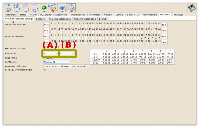

Control boards ET6, ET7 -
(A) Combo Box represents motor outputs 0,1,2,3;
(B) Combo Box represents channels 4,5.
Control boards ET1, ET10 -
(A) combo box is used to setup pulse width.
(B) combo box should be set to "0"
- Pulse width - selection pulses format - either PULSE/DIR or CW/CCW
Encoders

Analogue Closed Loop

Pulse-dir Closed Loop

ET2/ET4

Advanced
Config Manager
(Obsolete settings)

Load default settings
It's possible to select and set to default value some of settings like
- absolute/incremental programming(absolute)
- Feedrate dimension (unit/min)
- Linear programming unit (mm)
- Some of Tab Widgets visible state (Library, Diagnose, Settings, Editor, ROtate, Curtcharts)

Debug
Enable log of keys pressed by operator.

UI settings

Allow to edit cnc-screen.xml

This experimental option is very first attempt to graphic editor for UI. The option is activated if the checkbox selected and Save button pressed.
A window “Edit XML config item” with an item attributes will be shown by a mouse right click on the item. At the moment “button”, “display” and some other items are supported by “Edit XML config item”.
- It's possible to change attributes “Position X”, “PositionY”, “width”, “height” on-the-fly. The item will be moved/resized immediately
- It's possible to drag-n-drop the item with a mouse right button pressed
- Changing other attributes will take effect after the software restarted.
- If “Save” button pressed on the “Edit XML config item” window, new file “cnc-screen-custom.xml” will be created and used as the config. Original “cnc-screen.xml” will be untouched. To roll-back all the changes made in “Edit XML config item” window, just remove “cnc-screen-custom.xml”
The checkbox is cleared every time the Software loaded
and is not stored in configuration file for safety reason.

It turned out that a profile can be ruined very quickly with this feature.
We are considering to remove it for future releases.

