This is an old revision of the document!
Table of Contents
PLC
PLC - programmable logic controller.
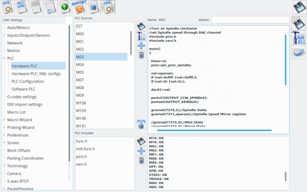
PLC controller can load and run small binary programs (PLC procedures). PLC procedure should be written in a simplified C-like language, compiled and stored in PLC controller memory to be ready to run. myCNC software includes PLC Builder - tiny IDE (Integrated Development Environment) to create and modify PLC procedure source files, compile them to binary code and upload it as RomFS iso image disk to PLC controller memory.
myCNC control has 2 types of built-in PLC systems that named Hardware PLC and Software PLC
Hardware PLC
“Hardware PLC” means PLC system runs inside the CNC control board and able to access directly to CNC controller peripherals (inputs, outputs, PWMs, DACs, ADCs etc). PLC has also API to access to Motion Controller of a myCNC control board, so positioning commands are possible from Hardware PLC.
Hardware PLC is a tiny virtual machine that runs pre-compiled PLC procedures. PLC procedure can be started from
- G-code program M-code
- On-screen button
- Input Pin
- From TCP Ethernet Socket through Server API
Hardware PLC loop cycle time is 1ms. PLC core runs PLC procedure until the end of next loop. At the end of each loop PLC sleeps for 1ms, then continue running PLC. N-times repeat loop (even empty) will be executed N milliseconds. For example, delay for 10ms can be programmes as
timer=10; do{timer--;}while(timer>0);
IMPORTANT.
Hardware PLC is single-tasking. Only one PLC process can be executed at the moment.
If new PLC procedure loaded, previous PLC process will be terminated immediately
and replaced by the new one.
PLC Language
- PLC operates with 32 bits integer values only. Floating point operations don't work in PLC.
- There is no need to declare variables. There is very limited space of 32 elements for variables.
- There a number of pre-defined variables in the PLC
- eparam - External Parameter variable. If M-code running from G-code program, 16-bit integer parameters P and L are sent to the PLC procedure in the eparam variable.
P-parameter in a low word of the eparam value and
L-parameter in high word of eparam value. To decode P and L parameters from eparam simple 2-lines code can be usedP=eparam&0xFFFF;//P-parameter L=eparam>>16; //L-parameter
- proc - variable is used to identify a process running in the PLC.
The value is sent to the CNC control software and can be used to display Current PLC state (like Idle, Ignition (for plasma cutting), preheat (gas cutting), Tool change, Probing etc) - timer - value can be used as time counter inside PLC procedure
- vexit - variable contains additional exit code. In case of error CNC control software can display Error message depends on vexit exit code.
- message. The message variable is handled every loop delay time. If message value is not “0” PLC controller sends to CNC control software message code and reset the variable to “0”.
- pwm01 - variable mapped to PWM #0 register. Writing to this variable will change PWM #0 value.
- pwm02 - variable mapped to PWM #1 register. Writing to this variable will change PWM #1 value.
- pwm03 - variable mapped to PWM #2 register. Writing to this variable will change PWM #2 value.
- pwm04 - variable mapped to PWM #3 register. Writing to this variable will change PWM #3 value.
- dac01 - variable mapped to DAC #0 register. Writing to this variable will change DAC #0 value.
- dac02 - variable mapped to DAC #1 register. Writing to this variable will change DAC #1 value.
- adc01 - variable mapped to ADC #0 register. Reading this variable will return ADC #0 value.
- adc02 - variable mapped to ADC #1 register. Reading this variable will return ADC #1 value. Variables adc01, adc02 are a bit obsolete. It's better to use gvarget, gvarset functions and The hardware access registers to access to the control board peripherals.
PLC is a tiny virtual machine with a very limited register and memory space.
PLC was created for very simple Inputs/Outputs manipulation.
Heavy algorithms cannot be handled by PLC.
Please keep in mind this while creating Hardware PLC procedure.
- PLC operators
| Operator | Description | Example |
|---|---|---|
+ | sum | c=a+200; |
- | subtract | c=a-150; |
* | multiply | c=a*b; |
/ | divide | c=b/7; |
& | logical AND | c=a&7; |
| | logical OR | c=b|1; |
>> | binary right shift | c=a>>16; |
<< | binary left shift | c=1<<n; |
== | equal to | if (a==20) ...... |
!= | not equal to | if (a!=0) ...... |
> | more than | if (b>0) ...... |
>= | more or equal than | if (a>=0xf) ...... |
< | less than | if (c<10) ...... |
<= | less or equal than | if (a⇐b) …… |
++ | variable post increment |

