Working material edge detection
The functionality to detect the edges of the working material is often used in CNC operations, for instance to properly position the G-code program onto the material if it was slightly moved or rotated (this often happens with heavy sheets of metal which are difficult to set down precisely). In this manual, we will be describing the ways in which a PLC designed for locating the edges of the working material can be created.
The code below is used for a custom profile which allows the system to detect the edges of the working material. In case of this example, it is done to then rotate the program based on the located edges. The overall procedure for the edge detection and rotation code in the example below is as follows (assuming the system starts over the material, i.e. the sensor is ON by default):
- Move in the Positive Y direction at high speed until the sensor is OFF (meaning that the sensor is no longer over the material)
- Move backwards (Negative Y) until the sensor is engaged again (ON)
- Save position
- Move in the Positive X direction until the sensor is OFF
- Move backwards (Negative X) until the sensor is engaged again (ON)
- Save position
- Jog in the positive Y direction for a set distance
- Move in the Positive X direction until the sensor is OFF
- Move backwards until the sensor is engaged again
- Save position
- Perform rotation based on the three saved points which denote the edges of the working material
Note that the M190.plc code is specific to a particular application that was built for a custom use case. The code below should be seen as a particular example to the broader task of locating and saving the position of the working material edges:
- M190.plc
//#include pins.h

#define INPUT_PROBE 13

#define ROLLBACK 2000

wait_move()
{
    do { code=gvarget(6060); }while(code!=0x4d);  //wait till motion finished
};

find_edgey()
{
  gvarset(8631,100); //acceleration time 50ms = 0.05s
  gvarset(8634,(2<<24)|speed); //Jog speed for Y
  gvarset(8635,2); //Jog in the Y+ direction
  timer=0;
  do
   {
      sensor0=portget(INPUT_PROBE);
      if ((timer&0xff)==0)   {     gvarset(8635,2);    };  //continue jog Y+ if the sensor is engaged
      timer++;
    }while(sensor0!=0);

  gvarset(8634,(2<<24)|speed_probe); //set lower probe speed for backwards motion for Y- direction
  gvarset(8635,2<<8); //Jog in Y- direction
  timer=0;
  do
   {
      sensor0=portget(INPUT_PROBE);
      if ((timer&0xff)==0)   {     gvarset(8635,2<<8);    }; //continue jog at probe speed until sensor is activated
      timer++;
    }while(sensor0==0);

   gvarset(8635,0); wait_move(); //stop jogging

};

find_edgex()
{
  gvarset(8631,100); //acceleration time 50ms = 0.05s
  gvarset(8634,(1<<24)|(speed*3)); //Jog speed for X
  gvarset(8635,1); //Jog in X+ direction
  timer=0;
  do
   {
      sensor0=portget(INPUT_PROBE);
      if ((timer&0xff)==0)   {     gvarset(8635,1);    };  //continue jog in X+ direction while sensor is ON
      timer++;
    }while(sensor0!=0);

  gvarset(8634,(1<<24)|(speed_probe*3)); //Jog speed for X
  gvarset(8635,1<<8); //X-
  timer=0;
  do
   {
      sensor0=portget(INPUT_PROBE);
      if ((timer&0xff)==0)   {     gvarset(8635,1<<8);    };
      timer++;
    }while(sensor0==0);

   gvarset(8635,0); wait_move();  //stop jogging

};


save_pos()
{

    gvarset(5730, 1);  timer=30;do{timer--;}while(timer>0); //save current position to calibration log

};


main()
{

  gvarset(5740, 1);  timer=30;do{timer--;}while(timer>0); //begin log

  gvarset(8631,100); //acceleration time 50ms = 0.05s
  gvarset(5539,1); //switch to fast g0moveA implementation


  gvarset(8632,44000); //speed X Position


  x0=gvarget(401)*50; //obtain user-inputted size of the working material (X-axis)
  y0=gvarget(402)*33; //obtain user-inputted size of the working material (Y-axis)

  g0moveA(0,0x1,x0); //move X 1/2 size
  do { code=gvarget(6060); }while(code==0);//wait till motion finished


  speed_probe=400;//gvarget(300);
  speed_fast=2000;//gvarget(301);
  speed=speed_fast;

  find_edgey();
  save_pos();

  gvarset(8632,44000); //speed
  g0moveA(0x3,0x1,300); //move X=0 (actually 3mm)
  do { code=gvarget(6060); }while(code==0);//wait till motion finished


  gvarset(8632,13000); //speed
  g0moveA(0,0x2,y0); //move Y 1/3 size incremental
  do { code=gvarget(6060); }while(code==0);//wait till motion finished

  find_edgex();
  save_pos();


  gvarset(8632,44000);
  g0moveA(0x3,0x1,300); //move X=0
  do { code=gvarget(6060); }while(code==0);//wait till motion finished

  gvarset(8632,13000);
  g0moveA(0,0x2,y0); //move Y 1/3 size incremental
  do { code=gvarget(6060); }while(code==0);//wait till motion finished

  find_edgex();
  save_pos();

  gvarset(5400,2); //switch tool to T2
  timer=500;do{timer--;}while(timer>0); //rotate based on 3 points

  gvarset(5740, 202);  timer=30;do{timer--;}while(timer>0); //rotate based on 3 points

  exit(99);  //normal exit
};

};
Note: the specific plate adjustment functionality shown in the code above does require the FlyCut license.
To go over specific sections of code in the code block above, let us start with the Find Edge (X & Y):
- find_edgex
find_edgex()
{
  gvarset(8631,100); //acceleration time 50ms = 0.05s
  gvarset(8634,(1<<24)|(speed*3)); //Jog speed for X
  gvarset(8635,1); //X+
  timer=0;
  do
   {
      sensor0=portget(INPUT_PROBE);
      if ((timer&0xff)==0)   {     gvarset(8635,1);    };
      timer++;
    }while(sensor0!=0);

  gvarset(8634,(1<<24)|(speed_probe*3)); //Jog speed for X
  gvarset(8635,1<<8); //X-
  timer=0;
  do
   {
      sensor0=portget(INPUT_PROBE);
      if ((timer&0xff)==0)   {     gvarset(8635,1<<8);    };
      timer++;
    }while(sensor0==0);

   gvarset(8635,0); //stop jog
   wait_move();

};
The code above goes through the following steps:
- Set the acceleration time and the jog speed for the X axis
- Begin moving in the positive X direction
- Keep jogging in that direction until the INPUT_PROBE sensor not registering the material
- Jog in the negative X direction at a slower speed until the sensor is activated again
- Stop jogging
A similar procedure is done for the Y direction.
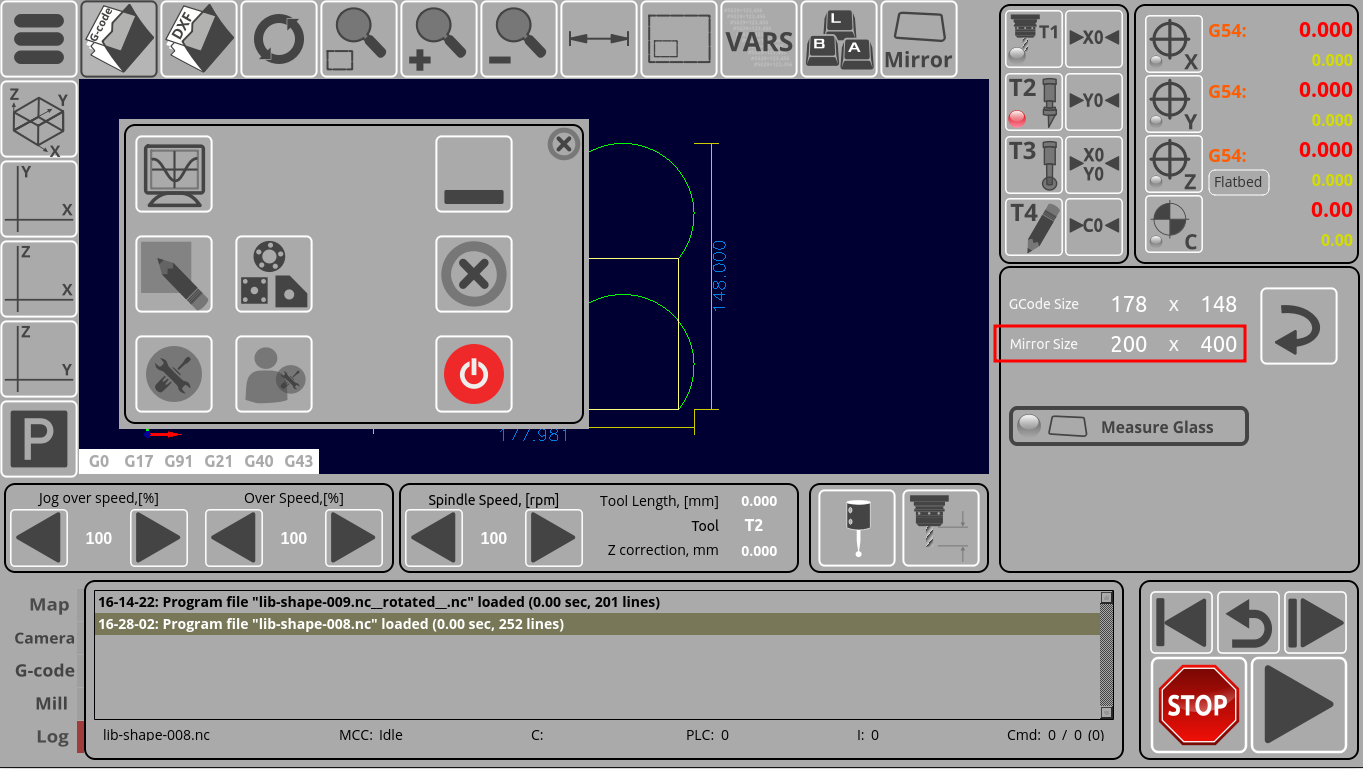
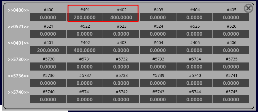
In the M190.plc code above, variables “x0” and “y0” are used, which are obtained by using the variables 401 & 402. In case of this specific example, the variables are taken from the data fields that are located on the main screen of the custom profile:
Therefore, for the following code:
  x0=gvarget(401)*50;
  y0=gvarget(402)*33;
  g0moveA(0,0x1,x0); //move X 1/2 size
  g0moveA(0,0x2,y0); //move Y 1/3 size incremental
the system will look at the current user-inputted values for global variables 401 and 402:
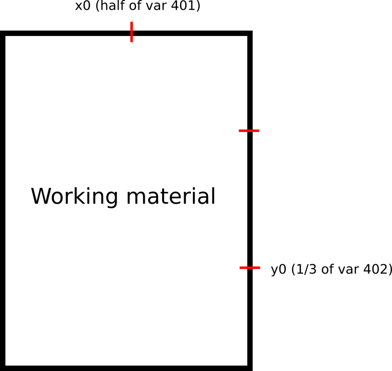
The multiplication by the factor of 50 (for X) and 33 (for Y) is done in order to “split” the area of the working material into 2 or 3 sections:
For g0moveA commands,distance to move is set to an integer value in 0.01 units. For instance, a command such as
g0moveA(0,1,1000);
would move the X axis 10 units to the right. Therefore, since we would typically need to multiply by 100 to convert a distance from regular units to the g0moveA command format, a code such as
x0=gvarget(401)*50;
is, in fact, dividing the distance by 2.
The save_pos function adds the current position to the log array by using the following code:
gvarset(5730, 1);
This will allow the system to compile three XY points which will serve as reference for the
gvarset(5740, 202); //rotate G-code file based on three points
command.
Relevant articles:


