Table of Contents
myCNC control software main screen description
The following describes the main windows and buttons within the X1366M4 profile.
The main screen of the 4 axes Mill profile is shown below:

Description of main screen buttons and windows
 | Go to the main window. |
 | Reorient the working area into an orthogonal view |
 | Reorient the file into an XY plane orientation |
 | Reorient the file into an XY plane orientation |
 | Reorient the file into an YZ plane orientation |
 | Open the Parking Window (see table below) |
 | Open a G-code file |
 | Open a DXF file |
 | Reload the program file from the hard drive |
 | Zoom - Fit to Window |
 | Zoom - Zoom In |
 | Zoom - Zoom Out |
 | Show dimensions of the nesting chart |
 | Show work area with the nesting chart |
 | Show the virtual keyboard |
 | Minimize the myCNC software |
 | Close the myCNC software |
 | Shut down the workstation. Note that this summons a script for the process (sudo poweroff). A similar system can be used for other actions, such as summoning applications. To have the summoned application give over control, use the “&” symbol in your custom .sh script. |
 | Open the myCNC settings |
 | Custom machine settings (see the manual for Speed Settings setup) |
 | A library of standard parts for cutting, milling, etc |
 | Open up the editor |
 | Open up the system diagnostics window |
 | Run the homing for the x-axis |
 | Run the homing for the y-axis |
 | Run the homing for the a-axis |
 | Run the homing for the xy plane |
 | Reset to zero the working x-coordinate |
 | Reset to zero the working y-coordinate |
 | Reset to zero the working z-coordinate |
 | Reset to zero the working a-coordinate |
 | Machine movement buttons (xy plane) |
 | Machine movement button (positive z-axis) |
 | Machine movement button (negative z-axis) |
 | Machine movement button (positive a-axis) |
 | Machine movement button (negative a-axis) |
 | Set the machine movement step size to a specified value |
 | Set the machine movement step size to 0.01 mm |
 | Set the machine movement step size to 0.1 mm |
 | Set the machine movement step size to 1 mm |
 | Set an infinite machine movement step size |
 | Go to the beginning of the control program |
 | Go forward |
 | Return to the working point |
 | Run the program |
 | Stop the program |
 | Go up one line in the program code |
 | Go down one line in the program code |
 | Go up ten lines in the program code |
 | Go down ten lines in the program code |
 | Open the Tool Specifications window (see table below) |
 | Open the Probe Sensor window (see table below) |
Progress window
The progress window is available on the latest M4 profile versions and is located on the lower part of the main profile screen:

The progress window shows the total number of lines in the program file, the current line that the running program is on, the progress bar, the elapsed time and the estimated time remaining.

Note that the progress bar will only work properly if the following settings is turned ON: “Check Soft Limits for the full toolpath” in Settings > Preferences > Start/Stop.

Parking Window buttons
The following Parking window opens upon pressing the Open the Parking Window button:

| | Open the Parking Window |
 | Move to selected parking position |
 | Save current position as Selected Parking |
 | Choose a preset parking position |
More info on the Parking widget and how to add it to profiles which don't display it by default:
Tool Specifications Window buttons
Upon pressing the Tool Specifications button, you are presented with the following window:

On newer profile and software versions, you are able to add additional buttons to the Tool window, by going into Settings > Advanced > UI settings:


The following buttons are available:
 | Run the tool length procedure (M421 macro) |
 | Run the surface measure procedure (M400 macro) |
 | Run the M06 macro |
 | Save the current state of the tools table |
 | Run the M425 command |
 | Set the tool setter offset |
 | Run the M421 command |
 | Close door |
 | Open door |
 | Console probe down |
 | Console probe up |
 | Left tool measure (M465) |
 | M464 X- Tool Measure |
 | M463 X+ Tool Measure |
 | M461 ZX- Tool Measure |
 | M460 ZX+ Tool Measure |
 | Right tool measure (M462) |
 | Offset X |
 | +Tune Z |
Note that button for the M421 macro (run tool length procedure) can work with either a confirmation dialog for the Rapid Speed Length (parameter #20), or without it. The code for the two buttons is shown below:
1) Option with confirmation
<gitem where="x-toolsview" position="10;10"
 width="860" height="605" name="toolsview" type="toolsview"
 fontStyle="normal" fontSize="12" noclose="1"
 tool-measure="confirm"
 bgColor="##b-main"  ></gitem>
2) Option without confirmation
<gitem where="x-toolsview" position="10;10"
 width="860" height="605" name="toolsview" type="toolsview"
 fontStyle="normal" fontSize="12" noclose="1"
 tool-measure="direct"
 bgColor="##b-main"  ></gitem>
Probe Sensor Window buttons
Upon pressing the Probe Sensor button on the main screen, you are presented with the following window:
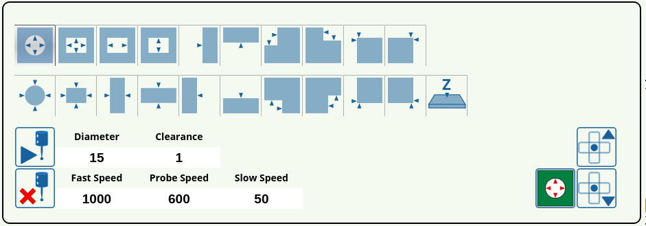 The probe sensor allows to find the edges and the corners of simple shapes and register those in the myCNC software. The following buttons can be utilized from within the software:
 | Run the centering procedure for a round hole |
 | Run the centering procedure for a rectangular hole |
 | Run the centering procedure for the internal x-axis |
 | Run the centering procedure for the internal y-axis |
 | Find the edge for the positive x-axis |
 | Find the edge for the positive y-axis |
 | Find the internal corner for the negative x- and positive y-axis |
 | Find the internal corner for the positive x- and positive y-axis |
 | Find external corner for negative x- and positive y-axis |
 | Find external corner for positive x- and positive y-axis |
 | Run centering for an external round shape |
 | Run centering for an external rectangular shape |
 | Run centering for an external x-axis |
 | Run centering for an external y-axis |
 | Find the edge for the negative x-axis |
 | Find the edge for the negative y-axis |
 | Find internal corner for positive x- and positive y-axis |
 | Find internal corner for negative x- and positive y-axis |
 | Find external corner for positive x- and positive y-axis |
 | Find external corner for negative x- and positive y-axis |
 | Find the surface in the z-axis |
 | Run the probing procedure |
 | Close the probing window |
 | Move to the hole center |
 | Move the probe console up |
 | Move the probe console down |
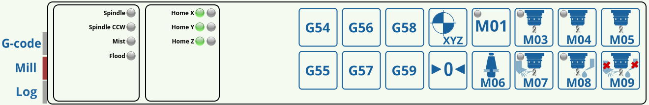
Mill Window buttons
Upon clicking the Mill button in the lower left corner of the main screen, you are presented with the following window:
 | Select the preferred coordinate system |
 | Run the homing procedure for all axes |
 | Move to work position |
 | Turn spindle on (clockwise rotation) |
 | Turn spindle on (counter-clockwise rotation) |
 | Turn spindle off |
 | Switch the working tool |
 | Turn the mist coolant on |
 | Turn the lubrication on |
 | Turn the coolant and lubrication off |
 | Conditional machine stop |
Run from here
In an event of an emergency stop or failure of a mill machine running a program file, it is often useful to be able to open the file back up afterwards and be able to continue from the middle of the program without having to go through all the steps again. This is often complicated by the fact that a large program file consists of many lines of code, making it difficult to easily navigate to the place where the cutting process stopped initially. In order to facilitate finding this spot, the Run from Here process is put in place in myCNC software.
Upon opening the G-Code tab and pressing the Run from here button, you are presented with the following screen:

Upon clicking the Run from Here button, the following screen is brought up:

If you know the particular line number from which you want to resume the cutting process, you can enter it in the Line Number field, and then press OK.

If, however, you do not know the particular line number at which the program was stopped, you can use the Found Position function in order to approximately locate the correct line.
In order to do so:
1. Navigate to the spot as close as possible to the one where the working tool has initially stopped using the onscreen buttons.

2. Click the Run from Here button.
3. Depending on the specifics of your part, you can choose to either use the search in the xy or the xyz planes. The xy search is mostly used for parts that are largely flat, without a significant z-axis component to them, while the xyz will try to locate the closest point in the program file for all three axis and is primarily used for 3D components.
For this example, xyz search will be chosen, as the part used is not a simple 2D projection.

After pressing the xyz button, the Found Position coordinates appear in the popup screen. Press OK.
4. After returning to the main screen, it can be seen that the white pointer has jumped to the new Found Position, and that the selected line is now different (1570 in this example).

The program can now be run from this position without having to manually search for the correct line.